User Guide#
This guide explains how to set up and use the Animation Graph editor: enabling the extension, creating and applying graphs, working with Blend Trees and State Machines, and controlling graphs from Python and Action Graph. You learn the main UI areas, graph modes, and how to drive variables at runtime.
Setup#
Enabling the Extension#
When you enable the omni.anim.graph.bundle extension, the Animation Graph panel appears. If the tab is closed while the extension is still loaded, open Window > Animation > Animation Graph to show it again. The omni.anim.graph.core extension provides the backend; omni.anim.graph.ui provides the frontend.
Home Screen#
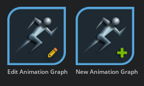
When no graph is loaded, a menu of options appears in the graph canvas. Buttons in the upper-left corner let you create a new graph or load an existing one from the scene.
Option |
Result |
|---|---|
Create New Animation Graph |
Creates a new Animation Graph. |
Select Animation Graph |
Opens a dialog to choose an existing graph. |
Drag and Drop an Existing Animation Graph |
Opens a graph by dragging it from the Content browser. |
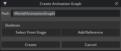
Creating a New Animation Graph#
When you create a new Animation Graph, the Create Animation Graph dialog opens. Select a Skeleton prim in the current scene or reference one from another scene.
Warning
Many features of the Animation Graph require a Skeleton at creation time. If you do not specify one, some features may be unavailable.
Option |
Result |
|---|---|
Path |
Displays or sets the location and name of the graph. |
Select from Stage |
Opens a dialog to select a Skeleton already in the scene. |
Select from Reference |
References a Skeletal Mesh from disk or a network location. |
Create |
Creates the Animation Graph and closes the dialog. |
Cancel |
Closes the dialog without saving changes. |
When you create a new Animation Graph, the final output node appears in the graph canvas and the node catalog lists available nodes on the left.
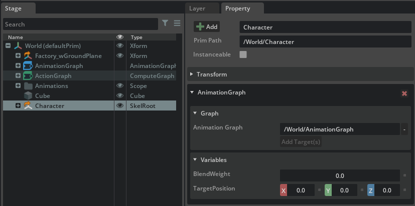
Applying an Animation Graph#
Although the graph has a Skeleton assigned, you must apply the graph to a SkelRoot for it to take effect. You can apply it to the same character used to build the graph or to other character SkelRoots.
To apply an Animation Graph to a skeletal mesh, right-click the SkelRoot in the Stage and choose Add > Animation > Animation Graph. In the SkelRoot Animation Graph section, use Add Target to specify the graph to apply.
Animation Graphs use instancing, so one graph can drive multiple characters without substantial memory overhead.
Note
Animation Retargeting can be combined with Animation Graphs to animate characters that are not initially compatible with the graph’s skeleton. Retargeting is executed as a post-process with the Animation Graph. Adding animations from different characters into the Animation Graph itself is not currently supported. All animations must conform to the skeleton the Graph is specified to use.
Working with Animation Graphs#
The Animation Graph editor consists of four areas:
Menu
Node Catalog
Variables
Canvas
The Menu#
The menu provides graph operations (new, open) and canvas utilities.

Option |
Result |
|---|---|
New |
Create a new animation graph |
Open |
Load an existing Animation Graph from the scene |
Node Visibility |
There are three options to control node display: Expand, Minimize, Close |
View |
Controls how nodes display and frames all nodes or the selected node(s) |
The Canvas#
This is the primary editor window where you add and edit node connections.
Option |
Result |
|---|---|
Breadcrumb Bar |
Displays the current depth of the graph and allows navigation between them. |
Node |
A programmatic function allowing an “action” to occur. Nodes are connected to create greater “higher order” utility. |
Display Depth |
Clicking on the “triple dots” of a given node collapse and expand the node displaying or hiding node details. |
Pin-Out |
Pin-outs offer outputs and display data type on rollover. |
Pin-Ins |
Node inputs; display expected data type on rollover. |
Noodle |
Drag from an output Pin-Out to a Pin-In to create a connection (noodle). |
Node Catalog#
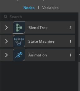
The Node Catalog lists the available nodes for the current graph mode.
The Node Catalog displays only nodes that are relevant to the current graph mode. For example, when you edit how a State Machine transitions between states, only the Transition condition graph nodes appear.
Variables#
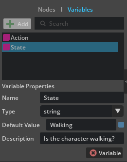
You can create variables of specific types and change them at runtime to control graph behavior. After you create variables, drag them onto the canvas and connect them to nodes.
Option |
Works In |
Stores |
Example |
|---|---|---|---|
Float |
BlendTree Only |
Floating Point Number |
2.344 |
Float3 |
BlendTree Only |
3 Floating Point Numbers |
2.34, 6.3, 5.7 |
Float3[] |
BlendTree Only |
Array of Float3 |
[[4.3, 3.71, 7.6], [4.9, 1.2, 5.2], …] |
Float4 |
BlendTree Only |
4 Floating Point Numbers |
8.8, 4.3, 3.7, 7.6 |
Float4[] |
BlendTree Only |
Array of Float4 |
[[8.8, 4.3, 3.7, 7.6], [2.2, 4.9, 1.2, 5.2], …] |
String |
BlendTree, State Machine Transitions |
Text Strings |
IsWalking |
Token[] |
BlendTree Only |
Cached String |
MyToken |
Graph Authoring Modes#
There are two core authoring modes of the Animation Graph editor: Blend Trees and State Machines.
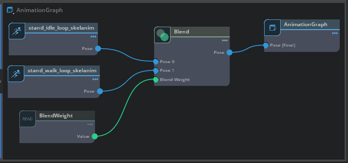
Blend Tree#
Blend Trees are the primary function of the graph and are used for mixing animations, controlling skeleton joints, and driving nodes via variable blend weights.
Name |
Description |
|---|---|
Blend |
Blends two inputs. Control the blend weight with the Alpha value. |
Motion Matching |
Uses motion clips plus movement and facing direction to find the best matching pose at runtime. The current implementation supports constant-lookup, useful for locomotion (walking, running, etc.). |
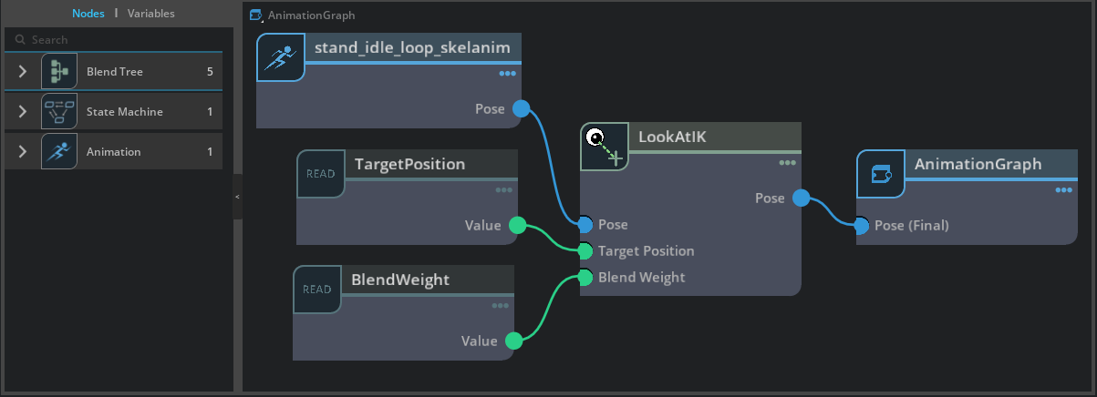
Look At IK |
Aims a joint within the Skeleton at a goal in the world; if a joint chain is specified, twists to blend the aim. |
Filter |
Removes animation on specified joints. Provide a space-separated list of joint names. |
Pose Provider |
Registers an external input (e.g. a live mocap stage) from outside the Animation Graph and brings it into the graph for further manipulation and blending via graph nodes. |
Two Bone IK |
Solves a two-bone chain (start, hinge, and end joints) to reach a target position; useful for arms and legs. |
State Machine |
Creates a new State Machine. Pack blend trees into behavior states and control which state is active and when to transition. Double-click to open the State Machine sub-graph. |
Note
When the extension setting enable_FBIK_nodes is enabled, additional Blend Tree nodes (Full Body IK, Set Effector) are available in the catalog.
State Machine#
State Machines let you control when and how to transition from one Blend Tree to another. Condition Graphs define this logic and control when a transition executes.
Add transitions by clicking the border of one state and dragging to another state. Double-click a transition arrow to view and edit the transition logic.
Tip
Blend Trees within one state can also contain an embedded State Machine. This nesting can be repeated as needed.
Name |
Description |
|---|---|
State |
Contains |
Transition |
Transitions are represented by arrow widgets between states. They specify a possible transition between states, and contain the control logic for transitioning from one state to another. |
Condition Compare Variable |
Within a transition, returns true if the specified string variable is or isn’t equal to another string variable. |
Condition Time Fraction Crossed |
Within a transition, returns true if the animation clip in the state reaches a percentage of play-through |
Condition Speed |
Within a transition, returns true when a speed variable meets the comparison threshold. |
Condition And |
Within a transition, returns true if both conditions are true |
Condition Or |
Within a transition, returns true if either condition is true |
Controlling Animation Graphs#
You can drive Animation Graph variables in two ways: Action Graph and Python. Both apply only when in Play mode.
Python#
Refer to the full list of Animation Graph API commands.
Action Graph#
Action Graphs are event based graphs within Omniverse.
You can create an Action Graph and assign it to a character that has an Anim Graph. Right-click the SkelRoot in the Stage and choose Add > OmniGraph. Assign the Action Graph in the property panel.
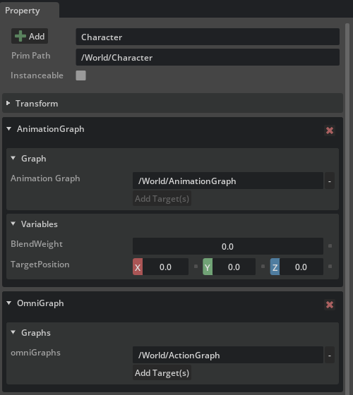
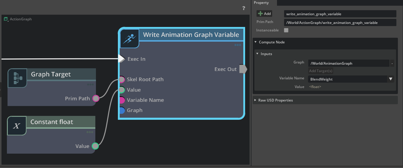
The Write Animation Graph Variable node controls an Animation Graph. Set the target Anim Graph and variable name on the node, connect the value to the Value port, and connect a Graph Target (Self on the SkelRoot) to Skel Root Path.
Note
All included Animation Graph samples are built using Action Graph as the primary control method.
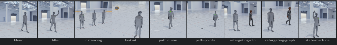
Samples#
Sample scenes that use the Animation Graph are in the Samples panel. Open Window > Browsers > Examples and go to Animation > Animation Graph in the tree.
Note
Samples use Action Graph to drive the Animation Graph. Open Action Graph from Window > Visual Scripting > Action Graph.
Tip
You can use the included sample assets in your own projects. To download the sample scene, use File > Save Flattened.
Summary#
You have learned how to enable the Animation Graph, create and apply graphs, work with Blend Trees and State Machines, and drive variables from Python and Action Graph. For a step-by-step workflow, refer to the AnimGraph Example Workflow. For the Python API, refer to the API Reference.