


Cameras#
OpenUSD’s camera model, UsdGeomCamera, models a basic pinhole camera. Additionally, RTX provides applied API schema to allow modeling fisheye and other distortion effects.
Note
Some camera properties may be overridden by a renderer.
Units#
Note that OpenUSD chooses to express several camera properties in units of “tenths of a scene unit” in order for a camera’s projection to continue to work if the entire scene is scaled. Tenths of a scene unit was chosen because of USD’s default scene unit, which is centimeters. So a 25mm focal length would be represented as 25 tenths of a scene unit. This often causes some confusion when a stage is, for example, in meters, in which case a 25mm focal length would be 0.25.
In the tables below, quantities measured in tenths of a scene unit are noted as “Tenths”. Care should be taken when setting those to match properties of a real device.
Lens#
Lens |
Description |
Units |
|---|---|---|
Focal Length |
Longer focal lengths produce a narrower FOV; shorter focal lengths produce a wider FOV.
|
Tenths
|
Focus Distance |
The distance at which perfect sharpness is achieved.
|
Scene Units
|
fStop |
Controls depth of field blur. Lower values narrow focus range; higher values widen it.
|
N/A
|
Projection |
Sets camera to perspective or orthographic mode.
|
N/A
|
Stereo Role |
Specifies stereoscopic role (left/right eye, mono (default), or non-stereo).
|
N/A
|
Aperture#
Aperture |
Description |
Units |
|---|---|---|
Aperture (Horizontal) |
Emulates sensor/film width on a camera.
|
Tenths
|
Aperture Offset (Horizontal) |
Offsets Resolution/Film gate horizontally.
|
Tenths
|
Aperture (Vertical) |
Emulates sensor/film height on a camera.
|
Tenths
|
Aperture Offset (Vertical) |
Offsets Resolution/Film gate vertically.
|
Tenths
|
Clipping#
Clipping |
Description |
Units |
|---|---|---|
Clipping Planes |
N/A
|
|
Clipping Range |
Clips the view outside of both near and far range values.
|
Scene Units
|
Rolling Shutter#

A propellor rendered with rolling shutter, showing the typical distortion of the propellor blades#
By default, RTX models a global shutter sensor, that is, a sensor where all photosites are exposed to light at the same time, and for the same duration. A rolling shutter sensor, by contrast, is a sensor where photosites are exposed to light progressively, often row by row. These sensors are typified by images where straight lines in motion become curved due to the offset in exposure time throughout the image, as shown in the example above.
Note
In order to use rolling shutter, motion raytracing must be enabled.
This can be done by specifying either one of the following settings:
--/renderer/raytracingMotion/enabled=trueto force-enable motion raytracing in all scenes.--/renderer/raytracingMotion/allowRuntimeToggle=trueto enable motion raytracing only when required (such as when a camera is using the rolling shutter feature).
Additionally, on Windows, --vulkan must be specified in order to use motion raytracing.
Specifying Per-Pixel Exposure Times#
In order to simulate rolling shutter, the renderer must know when during the frame each pixel should begin exposing to light. This is specified by a shutter time texture, which is expected to be a single-channel, floating-point OpenEXR image, where each pixel defines the exposure offset of the corresponding pixel in the rendered image.
If the dimensions of the shutter time texture and the render do not match, then the shutter time texture will be resized to match the render dimensions using linear interpolation.
A common use case is to have all pixels within a row expose at the same instant, while subsequent rows from top to bottom are offset from the previous row with a constant offset. In this case, the shutter time texture can be a single column with values ranging from 0.0 to 1.0, and all pixels within each rendered row will use the same value:
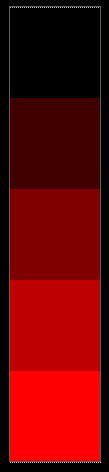
A single-column shutter timing texture with values ranging from 0.0 to 1.0 vertically#
Currently, the time value must be in the range [0, 1], where 0 specifies the start of the previous frame and 1 specifies the start of the current frame.
Note
Currently, each pixel is assumed to expose instantaneously. That is, the shutter time value just specifies the instant at which each pixel “sees” the scene and there will be no visible motion blur, just distortion.
Future versions will allow specifying both offset and exposure time to capture blur correctly, as well as allowing more flexibility in the timing (such as exposing over multiple “frames” of motion changes).
The example Python script below can be used to generate these textures with customizable line orders and sizes.
Shutter Timing Texture Generation Script
  1# Copyright (c) 2024, NVIDIA CORPORATION. All rights reserved.
  2#
  3# NVIDIA CORPORATION and its licensors retain all intellectual property
  4# and proprietary rights in and to this software, related documentation
  5# and any modifications thereto.  Any use, reproduction, disclosure or
  6# distribution of this software and related documentation without an express
  7# license agreement from NVIDIA CORPORATION is strictly prohibited.
  8
  9
 10# This script can generate textures compatible with the "GeneralizedProjectionTexture" lens projection.
 11# It generates a forward/inverse texture pair that drives the projection.
 12# This script can generate these textures by mimicing the existing omni fisheye projections
 13# and baking them as textures.
 14
 15# This python script will require pipinstalls for the following python libraries:
 16# /// script
 17# dependencies = [
 18#   "OpenEXR",
 19#   "numpy",
 20# ]
 21# ///
 22import OpenEXR
 23import Imath
 24import math
 25import numpy as np
 26
 27# Compression for the .exr output file
 28# Should be one of:
 29# NO_COMPRESSION | RLE_COMPRESSION | ZIPS_COMPRESSION | ZIP_COMPRESSION | PIZ_COMPRESSION
 30#g_compression = Imath.Compression.NO_COMPRESSION
 31g_compression = Imath.Compression.ZIP_COMPRESSION
 32
 33def save_img(img_path: str, img_data):
 34    """ Saving a numpy array to .exr file """
 35
 36    if img_data.ndim != 3:
 37        raise "The input image must be a 2-Dimensional image"
 38
 39    height = img_data.shape[0]
 40    width = img_data.shape[1]
 41    channel_count = img_data.shape[2]
 42
 43    channel_names = ['R', 'G', 'B', 'A']
 44
 45    channel_map = {}
 46    channel_data_types = {}
 47
 48    for i in range(channel_count):
 49        channel_map[channel_names[i]] = img_data[:, :, i].tobytes()
 50        channel_data_types[channel_names[i]] = Imath.Channel(Imath.PixelType(Imath.PixelType.FLOAT))
 51
 52    header = OpenEXR.Header(width, height)
 53    header['Compression'] = g_compression
 54    header['channels'] = channel_data_types
 55    exrfile = OpenEXR.OutputFile(img_path, header)
 56    exrfile.writePixels(channel_map)
 57    exrfile.close()
 58
 59def compute_shutter_time(width, height, pixel_tuples, time_tuples, is_scan_vertical):
 60
 61    assert len(pixel_tuples) == len(time_tuples), "pixel range tuples need to match time range tuples"
 62
 63    pixel_count = height if is_scan_vertical else width
 64    timing_per_pixel = np.zeros((pixel_count, 1), dtype=np.float32)
 65
 66    for pixel_range, time_range in zip(pixel_tuples, time_tuples):
 67        assert len(pixel_range) == len(time_range), "pixel range size need to match time range size"
 68        pixel_range_start = max(math.ceil(pixel_range[0] * pixel_count), 0)
 69        pixel_range_end = min(math.floor(pixel_range[1] * pixel_count), pixel_count-1)
 70        num_pixels = pixel_range_end - pixel_range_start + 1
 71        timing_per_pixel[pixel_range_start:pixel_range_end + 1, 0] = np.linspace(time_range[0], time_range[1], num = num_pixels)
 72        # print(timing_per_pixel)
 73
 74    return timing_per_pixel
 75
 76def generate_shutter_timing_texture():
 77    width = 1920
 78    height = 1080
 79
 80    is_scan_vertical = True
 81    is_scan_downwards_rightwards = True;
 82
 83    # Only applied for is_scan_vertical = true
 84    # A parameter set to determine different offsets of the exposure start (shutter open delay) within the line.
 85    # Parameter row_x shall be the normalized list of the tuple (pixel region x start, pixel region x stop)
 86    #row_x=[(0,0.5),(0.5,1)]
 87    row_x=[(0,1.0)]
 88    # Parameter row_t shall be a list of offset delay tuples which are defined by (delay start, delay end)
 89    # If the delay start and delay end differs, all values in between shall be linear interpolated between delay start and delay stop
 90    row_t=[(0.0,1.0)]
 91
 92    # Only applied for is_scan_vertical = false
 93    # A parameter set to describe the temporal offset of each line (readout delay)
 94    # The first parameter column_y shall be the normalized list of the tuple (pixel region y start, pixel region y stop)
 95    column_y=[(0,1.0)]
 96    # The second parameter column_t shall be a list of offset delay tuples of a line which are defined by (delay start, delay end)
 97    # If the delay start and delay end differs, all values in between shall be linear interpolated between delay start and delay stop
 98    column_t=[(0.000,1.000)]
 99
100
101
102    timing_per_pixel = compute_shutter_time(width, height, row_x, row_t, is_scan_vertical)
103
104    if not is_scan_vertical:
105        timing_per_pixel = np.transpose(timing_per_pixel)
106
107    img_data = np.zeros((height if is_scan_vertical else 1,  1 if is_scan_vertical else width, 1), dtype=np.float32)
108    img_data[:, :, 0] = timing_per_pixel[:, :]
109
110    scan_direction = "vertical" if is_scan_vertical else "horizontal"
111    save_img(f"shutter_time_{scan_direction}_{width}x{height}.exr", img_data)
112
113def main():
114    generate_shutter_timing_texture()
115
116
117if __name__ == "__main__":
118    main()
Assigning The Shutter Timing Texture#
To assign the shutter timing texture to a camera, set the camera’s asset shutterTimeTexturePath attribute. In Kit, this appears in the Shutter section in the Property Window.
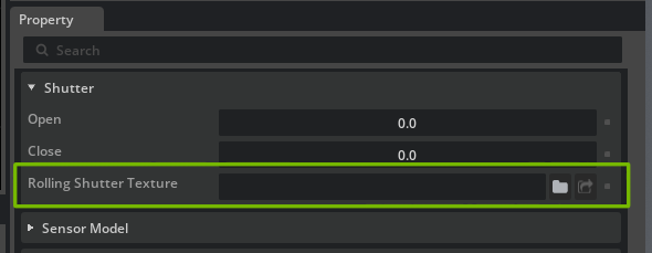
Once the shutter time texture is assigned, the camera will render with rolling shutter when the scene is in motion, for example by playing the timeline in Kit, or rendering a series of changes with movement in Sensor RTX.
Exposure#
The brightness of an image captured by a camera is a combination of the camera’s exposure time and other properties of the camera system. In a real camera, attributes such as the exposure time or aperture size will affect other properties of the image such as motion blur or depth of field. In OpenUSD these effects are separated to allow maximum control over the image generation and it is the user’s responsibility to ensure that the aperture used for depth of field matches the aperture used for exposure if that is desired.
Note
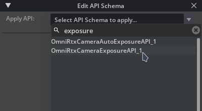
Camera exposure is a feature of OpenUSD 25.05. Until Kit upgrades to 25.05 or later, you can use these attributes by applying an instance of OmniRtxCameraExposureAPI_1 to your camera. The attributes in this schema have the same names as in OpenUSD 25.05 so will continue to work when USD is upgraded (at which point OmniRtxCameraExposureAPI_1 will become redundant).
How to Add Schemata to Cameras
Schemata can be applied using the OpenUSD Python API :
camera_prim = stage.DefinePrim("/World/Camera", "Camera")
camera_prim.ApplyAPI("OmniRtxCameraExposureAPI_1")
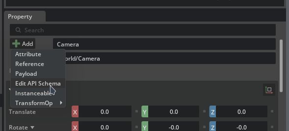
or by using the omni.kit.widget.schema_api extension. The Schema API widget adds functionality for adding a schema to a prim from the Property Window:
Attribute Name |
Type |
Default |
Description |
|---|---|---|---|
|
float |
0.0 |
Exposure compensation, as a log base-2 value. The default of 0.0 has no effect. A value of 1.0 will double the image-plane intensities in a rendered image; a value of -1.0 will halve them. |
|
float |
5.0 |
f-stop of the aperture when calculating exposure. Smaller numbers create a brighter image, larger numbers darker. Note that the |
|
float |
100.0 |
The speed rating of the sensor or film when calculating exposure. Higher numbers give a brighter image, lower numbers darker. |
|
float |
1.0 |
Scalar multiplier representing overall responsivity of the sensor system to light when calculating exposure. Intended to be used as a per camera/lens system measured scaling value. |
|
float |
1.0 |
Time in seconds that the sensor is exposed to light when calculating exposure. Longer exposure times create a brighter image, shorter times darker. Note that |
Note that the exposure attributes on a camera supersede those in the Render Settings -> Post-Processing -> Tone Mapping settings and allow you to set different exposures on different cameras. Once Kit upgrades to OpenUSD 25.05 or later, only the camera controls will work.
Lens Calibration#
The RTX Renderer supports a variety of lens distortion models to allow matching real-world measured cameras. Commonly used schema models include OpenCV pinhole and fisheye, a generalized LUT model, and omni-directional stereo.
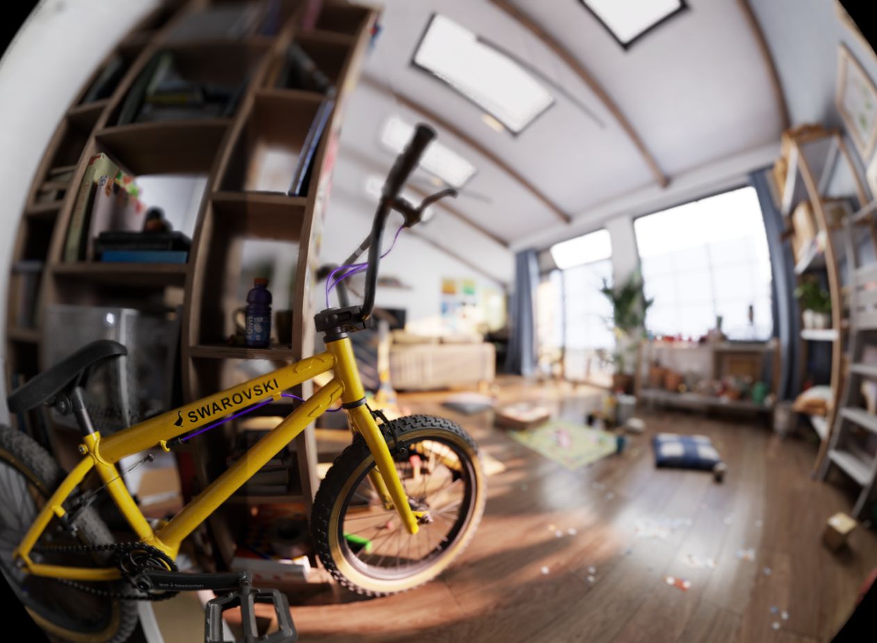
A scene rendered with a fisheye projection schema#
OmniLensDistortion Schemata#
The primary method of applying lens distortion to a camera is to use one of the OmniLensDistortion schemata, which are provided by the omni.usd.schema.omni_lens_distortion extension. For the generated API reference and complete schema attribute list, see the OmniLensDistortion schema documentation.
Note
When an OmniLensDistortion schema is applied, projection and distortion are driven entirely by the schema’s own parameters (fx, fy, cx, cy, imageSize, and the applicable k*, p*, and s* coefficients). The camera’s focalLength and aperture attributes are ignored for projection and distortion.
Depth of field is the exception: it continues to use the camera properties (focalLength, focusDistance, fStop) rather than the schema parameters.
Note
Several older cameraProjectionType values and their matching lens distortion models are supported for compatibility with existing calibrated cameras, but are deprecated. For new cameras, prefer OmniLensDistortionOpenCvPinholeAPI, OmniLensDistortionOpenCvFisheyeAPI, OmniLensDistortionLutAPI, or OmniLensDistortionOmniDirectionalStereoAPI. Use OmniLensDistortionLutAPI when you need to preserve a custom or wide projection that does not have a dedicated schema.
Legacy cameraProjectionType |
Use |
|---|---|
|
Bare |
|
|
|
|
|
|
|
|
|
|
|
The legacy projection remains supported. There is no dedicated OmniLensDistortion spherical schema; use |
How to Add Schemata to Cameras
Schemata can be applied using the OpenUSD Python API :
camera_prim = stage.GetPrimAtPath("/World/Camera")
camera_prim.ApplyAPI("OmniLensDistortionOpenCvPinholeAPI")
or by using the omni.kit.widget.schema_api extension. The Schema API widget adds functionality for adding a schema to a prim from the Property Window:
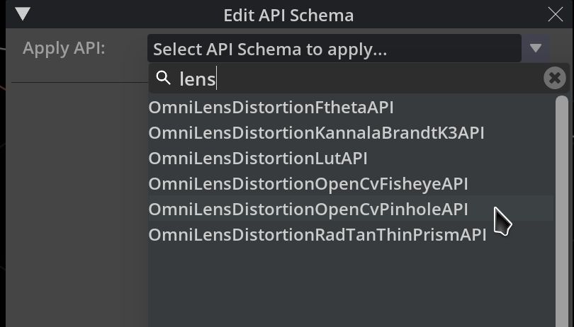
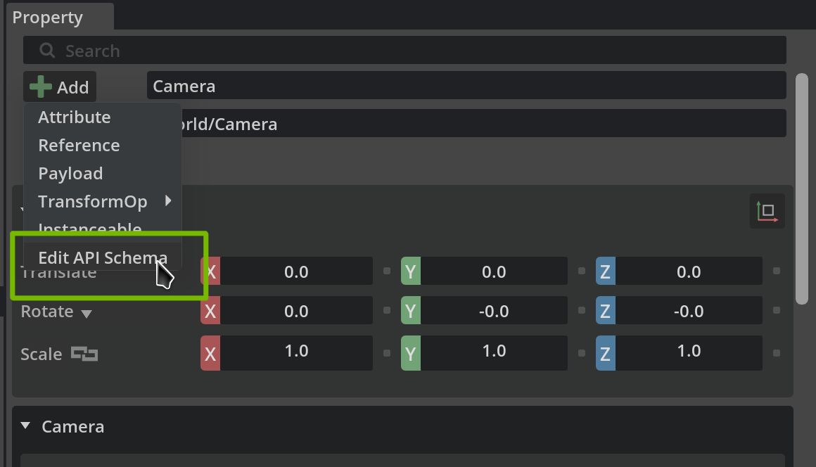
OmniLensDistortionOpenCvPinholeAPI#
Allows the use of OpenCV’s pinhole camera model.
Attribute Name |
Type |
Default |
Description |
|---|---|---|---|
omni:lensdistortion:model |
token |
opencvPinhole |
Allowed tokens: opencvPinhole |
omni:lensdistortion:opencvPinhole:cx |
float |
1024.0 |
|
omni:lensdistortion:opencvPinhole:cy |
float |
512.0 |
|
omni:lensdistortion:opencvPinhole:fx |
float |
900.0 |
|
omni:lensdistortion:opencvPinhole:fy |
float |
800.0 |
|
omni:lensdistortion:opencvPinhole:imageSize |
int2 |
(2048, 1024) |
Resolution, in pixels, that the calibration parameters ( |
omni:lensdistortion:opencvPinhole:k1 |
float |
0.0 |
|
omni:lensdistortion:opencvPinhole:k2 |
float |
0.0 |
|
omni:lensdistortion:opencvPinhole:k3 |
float |
0.0 |
|
omni:lensdistortion:opencvPinhole:k4 |
float |
0.0 |
|
omni:lensdistortion:opencvPinhole:k5 |
float |
0.0 |
|
omni:lensdistortion:opencvPinhole:k6 |
float |
0.0 |
|
omni:lensdistortion:opencvPinhole:p1 |
float |
0.0 |
|
omni:lensdistortion:opencvPinhole:p2 |
float |
0.0 |
|
omni:lensdistortion:opencvPinhole:s1 |
float |
0.0 |
|
omni:lensdistortion:opencvPinhole:s2 |
float |
0.0 |
|
omni:lensdistortion:opencvPinhole:s3 |
float |
0.0 |
|
omni:lensdistortion:opencvPinhole:s4 |
float |
0.0 |
OmniLensDistortionOpenCvFisheyeAPI#
Allows the use of OpenCV’s fisheye camera model.
Attribute Name |
Type |
Default |
Description |
|---|---|---|---|
omni:lensdistortion:model |
token |
opencvFisheye |
Allowed tokens: opencvFisheye |
omni:lensdistortion:opencvFisheye:cx |
float |
1024.0 |
|
omni:lensdistortion:opencvFisheye:cy |
float |
512.0 |
|
omni:lensdistortion:opencvFisheye:fx |
float |
900.0 |
|
omni:lensdistortion:opencvFisheye:fy |
float |
800.0 |
|
omni:lensdistortion:opencvFisheye:imageSize |
int2 |
(2048, 1024) |
Resolution, in pixels, that the calibration parameters ( |
omni:lensdistortion:opencvFisheye:k1 |
float |
0.00245 |
|
omni:lensdistortion:opencvFisheye:k2 |
float |
0.0 |
|
omni:lensdistortion:opencvFisheye:k3 |
float |
0.0 |
|
omni:lensdistortion:opencvFisheye:k4 |
float |
0.0 |
OmniLensDistortionLutAPI#
The generalized projection model enables arbitrary lens distortion modeling, both parametric and non-parametric, for any precision level given adequate calibration precision, with the use of user-provided textures.
Attribute Name |
Type |
Default |
Description |
|---|---|---|---|
omni:lensdistortion:lut:nominalHeight |
float |
1216.0 |
Height of the calibrated sensor |
omni:lensdistortion:lut:nominalWidth |
float |
1936.0 |
Width of the calibrated sensor |
omni:lensdistortion:lut:opticalCenter |
float2 |
(970.94244, 600.3748) |
|
omni:lensdistortion:lut:rayEnterDirectionTexture |
asset |
@@ |
Lookup table stored as an RGB image file where each RGB pixel value is the XYZ direction of rays entering the lens system in local camera space. |
omni:lensdistortion:lut:rayExitPositionTexture |
asset |
@@ |
Lookup table stored as an RG image file where each RG pixel value is the U,V coordinate in normalized screen space where the ray for that pixel is emitted from on the image plane. Values are in [0, 1] for on-screen positions; values outside that range are valid and indicate directions that land off screen. |
omni:lensdistortion:model |
token |
lut |
Allowed tokens: lut |
This model depends on generating two textures to define its octahedral encoding operations.
rayEnterDirectionTexture: Defines the unproject from NDC (Normalized Device Coordinate) to view direction operation. At runtime, for a given pixel, NDC is used as UVs to sample the Direction Texture and get the ray direction to trace primary rays.
The texture should be a 32-bit float texture with three channels (RGB) which encodes the three components of a normalized direction.
The texture should store information for the unproject from NDC (Normalized Device Coordinate) to view direction operation.
For each texel, coordinates range from (0,0) to (textureWidth, textureHeight):
Use the normalized texture coordinate (UV) at the texel center,
((i + 0.5) / textureWidth, (j + 0.5) / textureHeight), as the NDC. The renderer samples texel centers; registering samples on texel edges shifts the whole projection by half a texel.Call a user-defined unproject function, which should return a normalized view direction in float3.
Store the three components of the resulting view direction in R, G, and B channels of the image data array respectively.
Pack into an EXR image by calling save_img (provided in sample script).
The returned view direction must follow the renderer’s view-space conventions:
The camera looks down -Z, and view-space Y points up while NDC Y increases downward. For image NDC
(u, v)the direction is(sin(theta) * X / R, sin(theta) * Y / R, -cos(theta))withX = (u - cx) * nominalWidth / fx,Y = -(v - cy) * nominalHeight / fy, andR = sqrt(X^2 + Y^2). IfR == 0(the texel at the optical center), store(0, 0, -1). Note the Y negation and the per-axis normalization.Texels outside the calibrated field of view must store the sentinel direction
(0, 0, +1). It points directly backward, so the renderer’s field-of-view clip discards those rays, including any bilinear blend with valid neighboring texels. Set the camera’s maximum FOV to twice the calibrated half-angle so the runtime clip matches the baked domain.
rayExitPositionTexture: Defines the project from view direction or view position to NDC operation. At runtime, for a given view direction or view position, the texture’s encoded view direction is sampled as UVs to look up for the NDC, which is used to compute the corresponding pixel position on screen.
The texture should be a 32-bit float texture with two channels (RG) which encodes the two components of a normalized screen position (NDC).
The texture should store information for the project view space direction or position to NDC operation.
For each texel, coordinates range from (0,0) to (textureWidth, textureHeight):
Use the normalized texture coordinate (UV) at the texel center as the octahedral encoded view direction in float2.
Decode the encoded view direction using the script’s provided function get_octahedral_directions, then negate its Z component. The renderer flips Z before encoding, so view directions along the camera’s forward (-Z) axis are stored at the center of the texture; this keeps the imaged hemisphere away from the octahedral border seams. A texture baked without this flip produces correct still images but corrupted motion vectors.
Call a user-defined project function; the function should return a normalized device/screen coordinate in float2. On-screen positions range from (0,0) to (1,1); values outside that range are valid and mean the direction lands off screen. This texture has no sentinel value.
The returned coordinate must normalize X offsets by the nominal width and Y offsets by the nominal height, and negate the Y offset because NDC Y increases downward while view-space Y points up:
NDC = (cx + r * fx / nominalWidth * cos(psi), cy - r * fy / nominalHeight * sin(psi)).Store the two components of the resulting coordinate in the R and G channels of the image data array respectively.
Pack into an EXR by calling save_img (provided in sample script).
Note
Optical Center values should either be defined in the texture generation process or in the camera parameters. If defined by the textures, set the camera’s Optical Center values as half the Nominal Width and half the Nominal Height to avoid double-application. If not defined by the textures (i.e., texture is perfectly centered with (0.5, 0.5) as center), set the Optical Center in the camera parameters.
Note
Inaccurate projection artifacts may occur if the textures’ resolution is lower than the target view resolution.
Texture Generation Python Script Example
An example Python script to generate compatible OpenCV fisheye (Kannala-Brandt) textures which follow the model’s required convention is provided.
Python Script
  1# Copyright (c) 2024, NVIDIA CORPORATION. All rights reserved.
  2#
  3# NVIDIA CORPORATION and its licensors retain all intellectual property
  4# and proprietary rights in and to this software, related documentation
  5# and any modifications thereto.  Any use, reproduction, disclosure or
  6# distribution of this software and related documentation without an express
  7# license agreement from NVIDIA CORPORATION is strictly prohibited.
  8
  9
 10# This script can generate textures compatible with the "GeneralizedProjectionTexture" lens projection.
 11# It generates a forward/inverse texture pair that drives the projection.
 12# This script can generate these textures by mimicing the existing omni fisheye projections
 13# and baking them as textures.
 14# This python script will require pipinstalls for the following python libraries:
 15import OpenEXR
 16import Imath
 17import numpy as np
 18from numpy.polynomial.polynomial import polyval
 19
 20# Compression for the .exr output file
 21# Should be one of:
 22# NO_COMPRESSION | RLE_COMPRESSION | ZIPS_COMPRESSION | ZIP_COMPRESSION | PIZ_COMPRESSION
 23#g_compression = Imath.Compression.NO_COMPRESSION
 24g_compression = Imath.Compression.ZIP_COMPRESSION
 25
 26
 27# util functions
 28def save_img(img_path: str, img_data):
 29    """ Saving a numpy array to .exr file """
 30
 31    if img_data.ndim != 3:
 32        raise "The input image must be a 2-Dimensional image"
 33
 34    height = img_data.shape[0]
 35    width = img_data.shape[1]
 36    channel_count = img_data.shape[2]
 37
 38    channel_names = ['R', 'G', 'B', 'A']
 39
 40    channel_map = {}
 41    channel_data_types = {}
 42
 43    for i in range(channel_count):
 44        channel_map[channel_names[i]] = img_data[:, :, i].tobytes()
 45        channel_data_types[channel_names[i]] = Imath.Channel(Imath.PixelType(Imath.PixelType.FLOAT))
 46
 47    header = OpenEXR.Header(width, height)
 48    header['Compression'] = g_compression
 49    header['channels'] = channel_data_types
 50    exrfile = OpenEXR.OutputFile(img_path, header)
 51    exrfile.writePixels(channel_map)
 52    exrfile.close()
 53
 54
 55# decode an array of X and Y UV coordinates in range (0, 1) into directions
 56def oct_to_unit_vector(x,y):
 57    dirX, dirY = np.meshgrid(x, y)
 58    dirZ = 1 - np.abs(dirX) - np.abs(dirY)
 59
 60    sx = 2 * np.heaviside(dirX, 1) - 1
 61    sy = 2 * np.heaviside(dirY, 1) - 1
 62
 63    tmpX = dirX
 64    dirX = np.where(dirZ <= 0, (1 - abs(dirY))*sx , dirX)
 65    dirY = np.where(dirZ <= 0, (1 - abs(tmpX))*sy , dirY)
 66
 67    n = 1 / np.sqrt(dirX**2 + dirY**2 + dirZ**2)
 68    dirX *= n
 69    dirY *= n
 70    dirZ *= n
 71    return dirX, dirY, dirZ
 72
 73
 74# encode an array of view directions (unit vectors) into octahedral encoding
 75def unit_vector_to_oct(dirX, dirY, dirZ):
 76    n = 1 / (np.abs(dirX) + np.abs(dirY) + np.abs(dirZ))
 77    octX = dirX * n
 78    octY = dirY * n
 79
 80    sx = 2*np.heaviside(octX, 1) - 1
 81    sy = 2*np.heaviside(octY, 1) - 1
 82
 83    tmpX = octX
 84    octX = np.where(dirZ <= 0, (1 - abs(octY))*sx, octX)
 85    octY = np.where(dirZ <= 0, (1 - abs(tmpX))*sy, octY)
 86    return octX, octY
 87
 88
 89def get_texel_center_coordinates(size):
 90    """Return normalized texture coordinates at texel centers."""
 91    return (np.arange(size, dtype=np.float64) + 0.5) / size
 92
 93
 94# take the texture width and height, generate the view directions for each texel in an array
 95def get_octahedral_directions(width, height):
 96    # Match the renderer's (dispatchThreadId + 0.5) / dimensions sampling.
 97    # Octahedral vectors are encoded on the [-1,+1] square.
 98    x = get_texel_center_coordinates(width) * 2.0 - 1.0
 99    y = get_texel_center_coordinates(height) * 2.0 - 1.0
100
101    # octahedral to unit vector
102    dirX, dirY, dirZ = oct_to_unit_vector(x, y)
103
104    return dirX, dirY, dirZ
105
106
107def poly_KB(theta, coeffs_KB):
108    theta2 = theta**2
109    dist= 1 + theta2 * (coeffs_KB[1] + theta2 * (coeffs_KB[2] + theta2 * (coeffs_KB[3]+ theta2 * coeffs_KB[4])))
110    return theta*dist
111
112
113def poly_KB_prime(theta, coeffs_KB):
114    theta2 = theta * theta
115    return 1 + 3 * coeffs_KB[1] * theta2 + 5 * coeffs_KB[2] * theta2**2 + \
116        7 * coeffs_KB[3] * theta2**3 + 9 * coeffs_KB[4] * theta2**4
117
118
119def invert_poly_KB(radius, coeffs_KB, theta_max, iterations=4):
120    """Invert the KB polynomial inside the explicitly calibrated angular domain."""
121    if not np.isfinite(theta_max) or theta_max <= 0:
122        raise ValueError("theta_max must be a finite positive half-angle in radians")
123
124    radius_max = poly_KB(theta_max, coeffs_KB)
125    if not np.isfinite(radius_max) or radius_max <= 0:
126        raise ValueError("poly_KB(theta_max) must be finite and positive")
127
128    # Regula falsi requires a monotonic bracket. This only checks invertibility;
129    # it does not attempt to infer the calibration domain from the coefficients.
130    domain_theta = np.linspace(0.0, theta_max, 1025)
131    if np.any(poly_KB_prime(domain_theta, coeffs_KB) <= 0):
132        raise ValueError("KB polynomial is not strictly increasing on [0, theta_max]")
133
134    valid = np.isfinite(radius) & (radius >= 0) & (radius <= radius_max)
135
136    # One regula falsi step on [0, theta_max]. Because poly_KB(0) == 0,
137    # the false-position expression simplifies to this linear interpolation.
138    theta = np.zeros_like(radius, dtype=np.float64)
139    np.multiply(radius, theta_max / radius_max, out=theta, where=valid)
140    k1, k2, k3, k4 = coeffs_KB[1:5]
141
142    for _ in range(iterations):
143        theta2 = theta * theta
144        theta4 = theta2 * theta2
145        theta6 = theta4 * theta2
146        theta8 = theta4 * theta4
147
148        value = theta * (1 + k1 * theta2 + k2 * theta4 + k3 * theta6 + k4 * theta8)
149        derivative = 1 + 3 * k1 * theta2 + 5 * k2 * theta4 + 7 * k3 * theta6 + 9 * k4 * theta8
150        correction = np.zeros_like(theta)
151        np.divide(value - radius, derivative, out=correction, where=valid & (derivative != 0))
152        theta -= correction
153
154    residual = np.abs(poly_KB(theta, coeffs_KB) - radius)
155    tolerance = 1e-12 * np.maximum(1.0, radius)
156    if np.any(valid & (residual > tolerance)):
157        raise RuntimeError("KB inverse did not converge within the requested iterations")
158
159    return theta, valid
160
161
162#--unproject from sensor plane normalized coordindates to ray cosine directions
163def create_backward_KB_distortion(textureWidth, textureHeight, Width, Height,fx, fy,cx, cy,coeffs_KB, theta_max):
164    # Evaluate the NDC-to-direction map at texel centers. OpenCV intrinsics are
165    # in pixels, so X is normalized by image width and Y by image height.
166    screen_x = (get_texel_center_coordinates(textureWidth) - cx) * Width / fx
167    screen_y = -(get_texel_center_coordinates(textureHeight) - cy) * Height / fy
168
169    X, Y = np.meshgrid(screen_x, screen_y)
170
171    # Compute the radial distance on the screen from its center point
172    R = np.sqrt( X**2 + Y**2)
173
174    # Solve every texel simultaneously instead of invoking a scalar root solver
175    # once per texel. For the calibrated monotonic polynomial, a few Newton
176    # steps converge to machine precision (asserted inside invert_poly_KB).
177    theta, valid = invert_poly_KB(R, coeffs_KB, theta_max)
178
179    # Compute direction cosines. The guarded divide also handles an odd-sized
180    # texture whose center texel lands exactly on the optical axis.
181    inverse_R = np.divide(1.0, R, out=np.zeros_like(R), where=R != 0)
182    sin_theta = np.sin(theta)
183    dirX = np.where(valid, X * inverse_R * sin_theta, 0.0)
184    dirY = np.where(valid, Y * inverse_R * sin_theta, 0.0)
185    # +Z is the renderer's invalid-ray sentinel for this direction texture.
186    dirZ = np.where(valid, -np.cos(theta), 1.0)
187
188    return dirX, dirY, dirZ
189
190#--Project
191def create_forward_KB_distortion_given_directions(dirX, dirY, dirZ, Width, Height, fx, fy,cx, cy, coeffs_KB):
192    # compute theta between ray and optical axis
193    sin_theta = np.sqrt(dirX**2 + dirY**2)
194    theta = np.arctan2(sin_theta, -dirZ)
195
196    # appy forward distortion model
197    y=poly_KB(theta, coeffs_KB)
198
199    # Convert camera-plane coordinates to NDC. Renderer NDC Y increases from
200    # top to bottom, so projecting a +Y view direction requires a minus sign.
201    radial_scale = np.divide(y, sin_theta, out=np.zeros_like(y), where=sin_theta != 0)
202    ndcX = cx + dirX * radial_scale * fx / Width
203    ndcY = cy - dirY * radial_scale * fy / Height
204
205    return ndcX, ndcY
206
207
208def create_forward_KB_distortion_octahedral(width, height, Width, Height, fx, fy,cx, cy, coeffs):
209    # convert each texel coordinate into a view direction, using octahedral decoding
210    dirX, dirY, dirZ = get_octahedral_directions(width, height)
211
212    # The KB camera looks down -Z, whereas conventional octahedral decoding
213    # places +Z at the center of the map. Flip Z so the optical axis is at the
214    # map center and the unavoidable opposite-pole seam is moved to the edges.
215    dirZ = -dirZ
216
217    # project the decoded view direction into NDC
218    # TODO replace this call with your own `project` function
219
220    return create_forward_KB_distortion_given_directions(dirX, dirY, dirZ, Width, Height, fx, fy,cx, cy, coeffs)
221
222
223def generate_hq_fisheye_KB(textureWidth, textureHeight,Width, Height, fx, fy,centerX,centerY,polynomials, theta_max):
224    from datetime import datetime
225    # Create date string as part of texture file name
226    date_time_string = datetime.now().strftime("%Y_%m_%d_%H_%M_%S")
227
228    # Create encoding for "unproject", i.e. NDC->direction
229    dirX, dirY, dirZ = create_backward_KB_distortion(textureWidth, textureHeight,Width, Height, fx, fy,centerX, centerY, polynomials, theta_max)
230    dirX = dirX.astype("float32")
231    dirY = dirY.astype("float32")
232    dirZ = dirZ.astype("float32")
233
234    # image data has 3 channels
235    direction_img_data = np.zeros((textureHeight, textureWidth, 3), dtype=np.float32)
236    direction_img_data[:, :, 0] = dirX
237    direction_img_data[:, :, 1] = dirY
238    direction_img_data[:, :, 2] = dirZ
239    save_img(f"texture/fisheye_direction_{textureWidth}x{textureHeight}_unproject_KB_{date_time_string}.exr", direction_img_data)
240
241    # Create encoding for "project", i.e. direction->NDC
242    x, y = create_forward_KB_distortion_octahedral(textureWidth, textureHeight, Width, Height, fx, fy,centerX, centerY, polynomials)
243    x = x.astype("float32")
244    y = y.astype("float32")
245
246    # image data has 2 channels (NDC.xy)
247    NDC_img_data = np.zeros((textureHeight,textureWidth,2), dtype=np.float32)
248    NDC_img_data[:, :, 0] = x
249    NDC_img_data[:, :, 1] = y
250
251    # save the image as exr format
252    # ("negZ_in_center" marks the RTX contract layout: forward rays at the
253    #  texture center. Pairs without this marker may predate the convention
254    #  fix and should be triaged before use - see texture/README.md.)
255    save_img(f"texture/fisheye_NDC_{textureWidth}x{textureHeight}_project_KB_negZ_in_center_{date_time_string}.exr", NDC_img_data)
256
257
258def main():
259    # Generates high quality example texture based on opencv fisheye(KB) distortion model.
260
261    # Renderer resolution settings as desired
262    textureWidth = 3840
263    textureHeight = 2560
264
265    # Camera parameters from OpenCV calibration output or other sources
266    # Image resoluton
267    Width=1920
268    Height=1280
269
270    # Optical center
271    centerX = 0.5
272    centerY = 0.5
273
274    # Focal length
275    fx=731
276    fy=731
277
278    # OpenCV Fisheye model.
279    polynomials_KB = [1,-0.054776250681940974,-0.0024398746462049982,-0.001661261528356045,0.0002956774267707282]
280
281    # Maximum calibrated half-angle in radians. Keep this explicit: the
282    # polynomial coefficients do not encode their own validity domain.
283    theta_max = np.pi / 2
284
285    generate_hq_fisheye_KB(textureWidth, textureHeight,Width, Height, fx, fy,centerX,centerY,polynomials_KB, theta_max)
286
287
288if __name__ == "__main__":
289    main()
Note
The textures are generated in the EXR format, which can be viewed with apps such as RenderDoc, and the OpenEXR package can be installed via: pip install OpenEXR
Warning
Texture pairs generated with versions of this example published before August 2026 render correct images but corrupt motion vectors and temporal accumulation (TAA/DLSS ghosting or jitter), because the position texture was baked without the Z flip described above. To check an existing position texture, read its center texel: it should store approximately the configured optical center in normalized screen coordinates ((cx, cy) as used during generation; (0.5, 0.5) for a centered lens). If the corner texels store the optical center instead, regenerate the pair with the current script.
OmniLensDistortionOmniDirectionalStereoAPI#
Configures a single-eye Omni-Directional Stereo (ODS) camera for 360-degree VR rendering. A stereo ODS output is composed from separate left/right-eye cameras, commonly stacked vertically (top/bottom).
Attribute Name |
Type |
Default |
Description |
|---|---|---|---|
omni:lensdistortion:model |
token |
omniDirectionalStereo |
Allowed tokens: omniDirectionalStereo |
omni:lensdistortion:omniDirectionalStereo:isLeftEye |
bool |
false |
Whether this camera represents the left eye in the stereo pair. |
omni:lensdistortion:omniDirectionalStereo:interpupillaryDistance |
float |
0.064 |
Interpupillary distance (IPD) in meters. Symmetric offsets of −IPD/2 for the left eye and +IPD/2 for the right eye are applied automatically. |
Scene Partitions#
Different cameras may be used to render different parts of a scene. This can be useful, for example, to render many individual robot simulation environments in a single scene without the different environments being visible to each other.
Note
Scene partitioning is disabled by default. To enable it, use the setting --/renderer/scenePartitioning/enabled=true.
Partitions are declared using the token primvars:omni:scenePartition primvar. By setting this primvar to a non-empty token on a given prim, that prim and all its descendents will be assigned to that partition.
At this point, only cameras that have a matching token omni:scenePartition attribute will render that prim and its descendents. Any cameras that do not have a matching token omni:scenePartition attribute will not render that prim and its descendents, including cameras that do not have an omni:scenePartition attribute set at all.
Conversely, any prims that are not assigned to a partition will be rendered by ALL cameras.
For example, consider the following scene consisting of a ground and two logo objects, with three cameras: one, Camera pointing straight down, another, Camera_left angled from the left, and a third, Camera_right angled from the right.
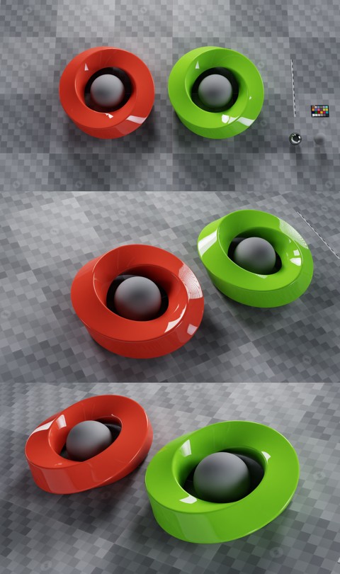
Camera_left has omni:scenePartition = "left", and Camera_right has omni:scenePartition = "right". Since no partitions have been assigned to any prims, the entire scene is visible in all cameras.
Now, if the red Logo_left is assigned primvars:omni:scenePartition = "left" then it disappears from the view of both Camera and Camera_right, but is still visible in Camera_left:
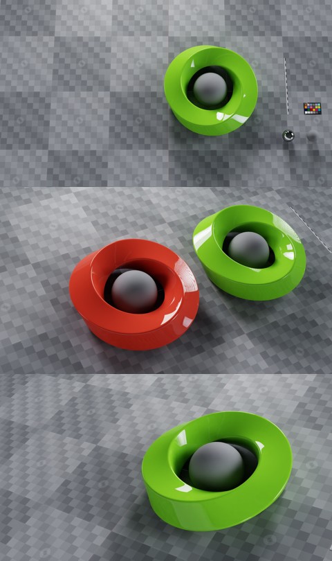
The red logo has “left” assigned to its top-level Xform so it disappears from the view of both Camera and Camera_right, but is still visible in Camera_left#
And finally, if the green Logo_right is assigned primvars:omni:scenePartition = "right" then it disappears from the view of both Camera and Camera_left, but is still visible in Camera_right:
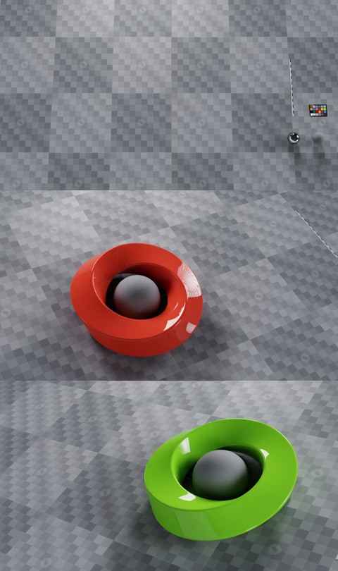
The green logo has “right” assigned to its top-level Xform so it disappears from the view of both Camera and Camera_left, but is still visible in Camera_right#
Note that the background objects that have not been assigned a partition are still visible in all cameras.
Limitations#
In the current version, the following prim types are not supported with scene partitioning:
DomeLights. All other light types do work.
Deforming geometry. Static geometry works correctly, but deforming geometry may clip to its undeformed bounds.
These limitations will be removed in a future version.