Camera Sensors and Render Extensions#
Camera Sensors can be created through adding a camera prim in the usd file. Data can be acquired then from the camera prim through the use of render products.
Render products can be created through multiple extensions in Omniverse such as viewport and replicator.
Note
The Omniverse Isaac Sim cameras are developed from the Omniverse cameras.
GUI Example#
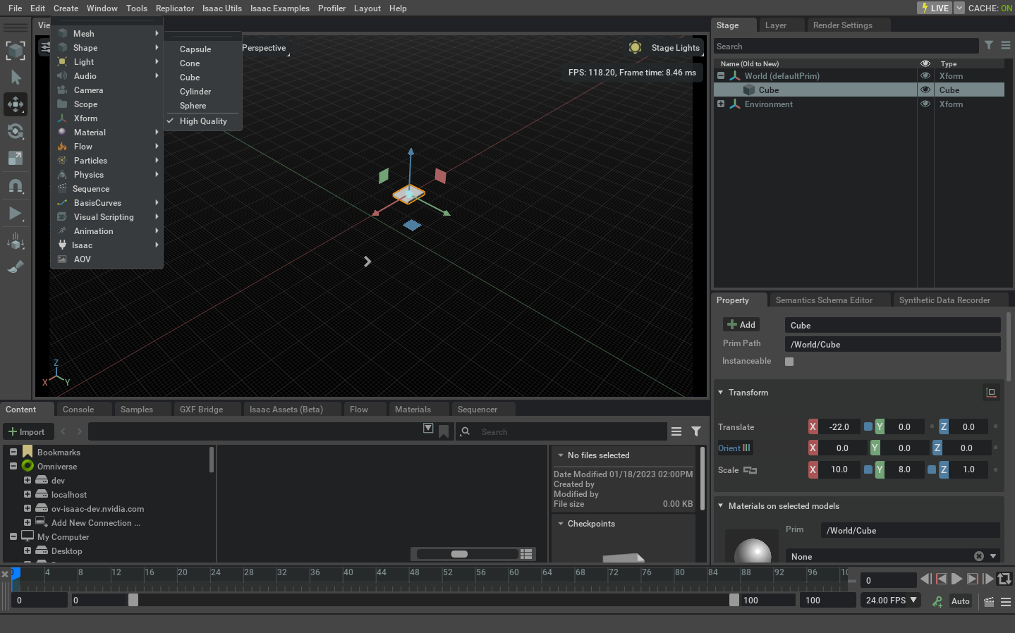
Create a cube by selecting Create > Shape > Cube and change its location and scale through the property panel as indicated in the screenshot below.
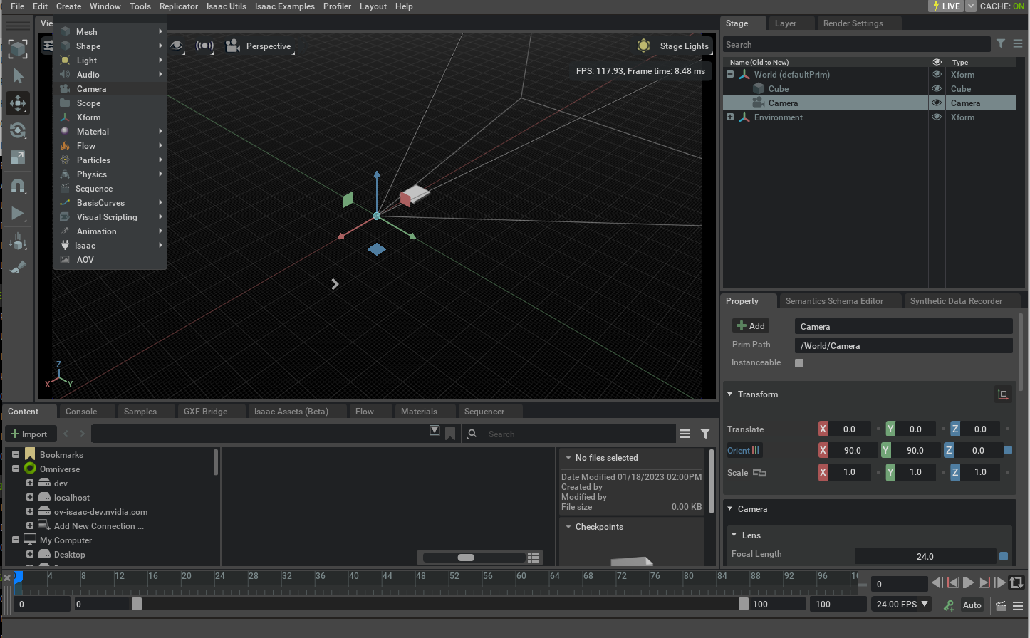
Create a camera prim by selecting Create > Camera and then select it from the stage window to view its field of view as indicated below.
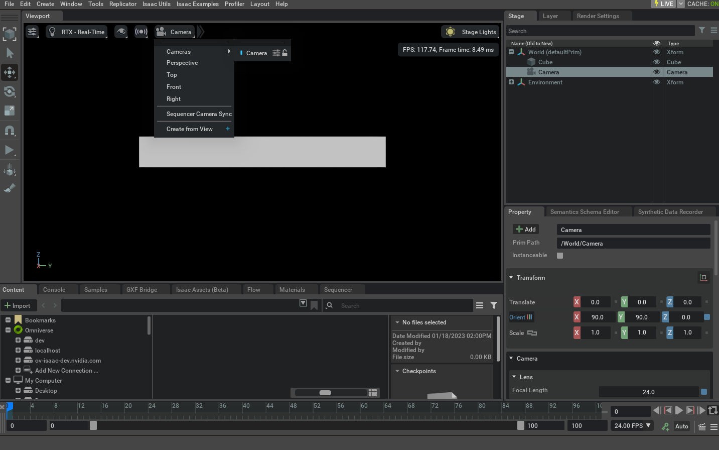
In order to render the frames from the camera we can switch the default viewport (which is a render product by itself) to the camera prim that we just created. Select the video icon at the top of the viewport window and then select the camera prim we just created under the cameras menu.
Python Example#
Data can be retrieved from the render product attached to the camera prim using multiple extensions in Isaac Sim. One of the methods provided is the Camera class under omni.isaac.sensor extension. Run the script below as a standalone application which is also provided at standalone_examples/api/omni.isaac.sensor/camera.py.
1from isaacsim import SimulationApp
2
3simulation_app = SimulationApp({"headless": False})
4
5from omni.isaac.core.objects import DynamicCuboid
6from omni.isaac.sensor import Camera
7from omni.isaac.core import World
8import omni.isaac.core.utils.numpy.rotations as rot_utils
9import numpy as np
10import matplotlib.pyplot as plt
11
12
13my_world = World(stage_units_in_meters=1.0)
14
15cube_2 = my_world.scene.add(
16 DynamicCuboid(
17 prim_path="/new_cube_2",
18 name="cube_1",
19 position=np.array([5.0, 3, 1.0]),
20 scale=np.array([0.6, 0.5, 0.2]),
21 size=1.0,
22 color=np.array([255, 0, 0]),
23 )
24)
25
26cube_3 = my_world.scene.add(
27 DynamicCuboid(
28 prim_path="/new_cube_3",
29 name="cube_2",
30 position=np.array([-5, 1, 3.0]),
31 scale=np.array([0.1, 0.1, 0.1]),
32 size=1.0,
33 color=np.array([0, 0, 255]),
34 linear_velocity=np.array([0, 0, 0.4]),
35 )
36)
37
38camera = Camera(
39 prim_path="/World/camera",
40 position=np.array([0.0, 0.0, 25.0]),
41 frequency=20,
42 resolution=(256, 256),
43 orientation=rot_utils.euler_angles_to_quats(np.array([0, 90, 0]), degrees=True),
44)
45
46my_world.scene.add_default_ground_plane()
47my_world.reset()
48camera.initialize()
49
50i = 0
51camera.add_motion_vectors_to_frame()
52
53while simulation_app.is_running():
54 my_world.step(render=True)
55 print(camera.get_current_frame())
56 if i == 100:
57 points_2d = camera.get_image_coords_from_world_points(
58 np.array([cube_3.get_world_pose()[0], cube_2.get_world_pose()[0]])
59 )
60 points_3d = camera.get_world_points_from_image_coords(points_2d, np.array([24.94, 24.9]))
61 print(points_2d)
62 print(points_3d)
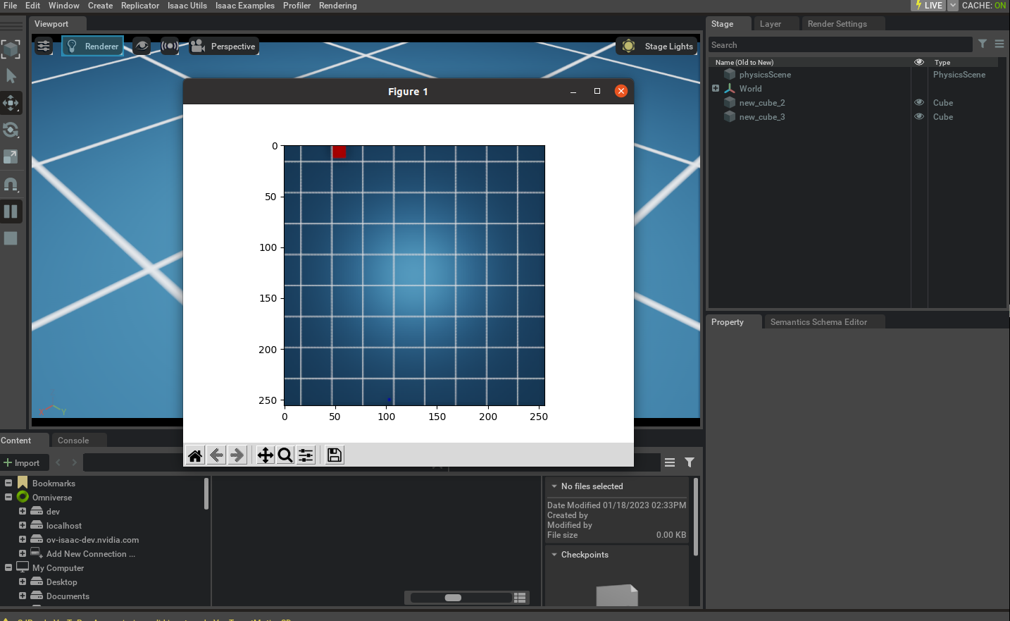
63 imgplot = plt.imshow(camera.get_rgba()[:, :, :3])
64 plt.show()
65 print(camera.get_current_frame()["motion_vectors"])
66 if my_world.is_playing():
67 if my_world.current_time_step_index == 0:
68 my_world.reset()
69 i += 1
70
71
72simulation_app.close()
Calibrated Camera Sensors#
Isaac Sim simulation approximates real camera sensors by ray tracing the scene and rendering the result. To achieve that the size of the camera sensor and optical path needs to be defined.
Calibration toolkits, like OpenCV or ROS normally provide the calibration parameters in a form an intrinsic matrix and distortion coefficients. While Isaac Sim uses physical units for the camera sensor size and focal length. To convert the calibration parameters to the Isaac Sim units, the following example can be used:
 1# OpenCV camera matrix and width and height of the camera sensor, from the calibration file
 2width, height = 1920, 1200
 3camera_matrix = [[958.8, 0.0, 957.8], [0.0, 956.7, 589.5], [0.0, 0.0, 1.0]]
 4
 5# Pixel size in microns, aperture and focus distance from the camera sensor specification
 6# Note: to disable the depth of field effect, set the f_stop to 0.0. This is useful for debugging.
 7pixel_size = 3 * 1e-3   # in mm, 3 microns is a common pixel size for high resolution cameras
 8f_stop = 1.8            # f-number, the ratio of the lens focal length to the diameter of the entrance pupil
 9focus_distance = 0.6    # in meters, the distance from the camera to the object plane
10
11# Calculate the focal length and aperture size from the camera matrix
12((fx,_,cx),(_,fy,cy),(_,_,_)) = camera_matrix
13horizontal_aperture =  pixel_size * width                   # The aperture size in mm
14vertical_aperture =  pixel_size * height
15focal_length_x  = fx * pixel_size
16focal_length_y  = fy * pixel_size
17focal_length = (focal_length_x + focal_length_y) / 2         # The focal length in mm
18
19# Set the camera parameters, note the unit conversion between Isaac Sim sensor and Kit
20camera.set_focal_length(focal_length / 10.0)                # Convert from mm to cm (or 1/10th of a world unit)
21camera.set_focus_distance(focus_distance)                   # The focus distance in meters
22camera.set_lens_aperture(f_stop * 100.0)                    # Convert the f-stop to Isaac Sim units
23camera.set_horizontal_aperture(horizontal_aperture / 10.0)  # Convert from mm to cm (or 1/10th of a world unit)
24camera.set_vertical_aperture(vertical_aperture / 10.0)
25
26camera.set_clipping_range(0.05, 1.0e5)
Notice that the script above is an initial approximation. Its limitations are the camera sensor is in the center of the image plane and that the pixels are square. To extend this approximation a distortion model needs to be added. The following models are supported by the rendering engine:
Note
To support intrinsics with the camera sensor outside of the center of the image plane it is necessary to add a distortion model. Non-square pixels are not supported by the rendering engine.
Model |
Description |
|---|---|
Pinhole (rectilinear) |
|
Fisheye Orthographic |
|
Equidistant |
|
Equisolid (equal area) |
|
Polynomial (f-theta) |
|
Kannala Brandt 2006 |
|
RadTanThinPrism |
Distortion parameters are normally provided by the calibration toolkits in a form of distortion coefficients. With most popular methods being Rational Polynomial, Brown Conrady, and Fisheye. These models are currently supported by approximating them with the f-theta model.
Below are a few examples of how to convert the calibration parameters from OpenCV and ROS calibration toolkits to the Isaac Sim units. The examples assume that the camera sensor pixels are square.
OpenCV Rational Polynomial Example#
To convert the OpenCV Rational Polynomial calibration parameters to the Isaac Sim units, the following example can be used (the script below as a standalone application which is also provided at standalone_examples/api/omni.isaac.sensor/camera_opencv.py):
 1# Given the OpenCV camera matrix and distortion coefficients (Rational Polynomial model),
 2width, height = 1920, 1200
 3camera_matrix = [[958.8, 0.0, 957.8], [0.0, 956.7, 589.5], [0.0, 0.0, 1.0]]
 4distortion_coefficients = [0.14, -0.03, -0.0002, -0.00003, 0.009, 0.5, -0.07, 0.017]
 5
 6# Define the field of view to be rendered (diagonal), pixels outside that FOV will be black
 7diagonal_fov = 140
 8
 9# Take the optical center in pixels from the camera matrix, and set the distortion coefficients
10((fx,_,cx),(_,fy,cy),(_,_,_)) = camera_matrix
11camera.set_projection_type("fisheyePolynomial")           # f-theta model, to approximate the model
12camera.set_rational_polynomial_properties(width, height, cx, cy, diagonal_fov, distortion_coefficients)
OpenCV Fisheye Calibration Example#
To convert the OpenCV Fisheye calibration parameters to the Isaac Sim model, the following example can be used (see standalone_examples/api/omni.isaac.sensor/camera_opencv_fisheye.py for the complete example):
 1# Given the OpenCV camera matrix and distortion coefficients (Fisheye model),
 2width, height = 1920, 1200
 3camera_matrix = [[455.8, 0.0, 943.8], [0.0, 454.7, 602.3], [0.0, 0.0, 1.0]]
 4distortion_coefficients = [0.05, 0.01, -0.003, -0.0005]
 5
 6# Define the field of view to be rendered (diagonal), pixels outside that FOV will be black
 7diagonal_fov = 235
 8
 9# Take the optical center in pixels from the camera matrix, and set the distortion coefficients
10((fx,_,cx),(_,fy,cy),(_,_,_)) = camera_matrix
11camera.set_projection_type("fisheyePolynomial")           # f-theta model, to approximate the fisheye model
12camera.set_kannala_brandt_properties(width, height, cx, cy, diagonal_fov, distortion_coefficients)
ROS Calibration Example#
In this example a printout of a of ROS topic, containing the intrinsic and extrinsic parameters of the camera will be used to create a camera sensor in Isaac Sim. It assumes that a physical camera sensor is calibrated by the vendor or by ROS Camera Calibration toolkit. And the calibration is published as a ROS topic.
As a first step, print the camera_info topic with:
rostopic echo /camera/color/camera_info
The output will look similar to the following (Intel® RealSense™ Depth Camera D435i is used here as an example):
frame_id: "camera_color_optical_frame"
height: 480
width: 640
distortion_model: "rational_polynomial"
D: [0.0, 0.0, 0.0, 0.0, 0.0, 0.0, 0.0, 0.0]
K: [612.4178466796875, 0.0, 309.72296142578125, 0.0, 612.362060546875, 245.35870361328125, 0.0, 0.0, 1.0]
R: [1.0, 0.0, 0.0, 0.0, 1.0, 0.0, 0.0, 0.0, 1.0]
P: [612.4178466796875, 0.0, 309.72296142578125, 0.0, 0.0, 612.362060546875, 245.35870361328125, 0.0, 0.0, 0.0, 1.0, 0.0]
Note
The distortion model could be “plumb_bob” or “pinhole”. In this example we will use the “rational_polynomial” model. To use these models, set the distortion_model to “rational_polynomial” and compliment array D with 0.0 to 8 elements.
Note
The camera_info topic in the Isaac Sim ROS bridge will be in the Rational Polynomial format.
Then, as a second step, open standalone_examples/api/omni.isaac.sensor/camera_ros.py and copy the output into the yaml_data variable. Populate additional parameters using the sensor manual:
1pixel_size = 1.4  # Pixel size in microns, 3 microns is common
2f_stop = 2.0  # F-number, the ratio of the lens focal length to the diameter of the entrance pupil
3focus_distance = 0.5  # Focus distance in meters, the distance from the camera to the object plane
Run the script as a standalone application. It will create a camera and a sample scene, render an image and save it to camera_ros.png file. The asset is also saved to camera_ros.usd file.
python.sh standalone_examples/api/omni.isaac.sensor/camera_ros.py
As an option, to validate the rendering product, this script also allows to overlay the rendered image with a few points projected by the OpenCV distortion model. To enable it, install the OpenCV python package:
python.sh -m pip install opencv-python
Extrinsic Calibration#
Extrinsic calibration parameters are normally provided by the calibration toolkits in a form of a transformation matrix. The convention between the axis and rotation order is important and it varies between the toolkits.
To set the extrinsic parameters for the individual camera sensor, use the following example to convert the transformation matrix from the calibration toolkit to the Isaac Sim units:
 1import numpy as np
 2import omni.isaac.core.utils.numpy.rotations as rot_utils       # convenience functions for quaternion operations
 3
 4dX,dY,dZ = ...  # Extrinsics translation vector from the calibration toolkit
 5rW,rX,rY,rZ =   # Note the order of the rotation parameters, it depends on the toolkit
 6
 7Camera(
 8    prim_path="/rig/camera_color",
 9    position    =  np.array([-dZ, dX, dY])      # Note, translation in the local frame of the prim
10    orientation =  np.array([rW, -rZ, rX, rY])  # quaternion orientation in the world/ local frame of the prim
11                                                # (depends if translation or position is specified)
12)
As an alternative, the camera sensor can be attached to a prim. In that case, the camera sensor will inherit the position and orientation from the prim.
 1import omni.isaac.core.utils.prims as prim_utils
 2
 3camera_prim = prim_utils.create_prim(
 4    name,
 5    "Xform",
 6    translation = ...
 7    orientation = ...
 8)
 9
10camera = Camera(
11    prim_path=f"{name}/camera",
12    ...
13)
Creating Camera Sensor Rigs#
The camera sensor rig is a collection of camera sensors that are attached to a single prim. It can be assembled from the individual sensors, that are either created manually or derived from the calibration parameters.
This will be a short discussion on how we created a digital twin of the Intel® RealSense™ Depth Camera D455. The usd for the camera can be found in the content folder as: `/Isaac/Sensors/Intel/RealSense/rsd455.usd.
There are three visual sensors, and one IMU sensor on the RealSense. Their placement relative to the camera origin was taken from the layout diagram in the TechSpec document from Intel’s web site.
Most camera parameters were also found in the TechSpec, for example, the usd parameter fStop is the denominator of the F Number from the TechSpec; the focalLength is the Focal Length, and the ftheatMaxFov
is the Diagonal Field of View. However, some parameters, like the focusDistance were estimated by comparing real output and informed guesses.
The horizontalAperture and verticalAperture in that example are derived from the technical specification. From the TechSpec, the left, right, and color sensors are listed as a OmniVision Technologies OV9782, and
the Tech Spec for that sensor lists the image area as 3896 x 2453 µm. We used that as the aperture sizes.
The resolution for the depth and color cameras are 1280 x 800, but it’s up to the user to attach a render product of that size to the outputs.
The Pseudo Depth camera is a stand in for the depth image created by the camera’s firmware. We don’t attempt to copy the algorithms that create the image from stereo, but the Camera_Pseudo_Depth component
is a convenience camera that can return the scene depth as seen from that camera position between the left and right stereo cameras. It would be more accurate to create a depth image from stereo, and if
the same algorithm that is used in the RealSense was used then the same results (including artifacts) would be produced.