Camera Calibration (Omni.Replicator.Agent.Camera_calibration)#
Omni.Replicator.Agent.Camera_calibration provides camera information for cameras generated by the Omni.Replicator.Agent (ORA) extension. You can use this extension to select a top-view camera within the stage to create the stage layout. Details including camera direction, location, and FOV polygon information are also captured and saved as a JSON file. For each camera generated by ORA, the FOV polygon is visually represented in the stage layout.
Activate the Extension#
On Window > Extension, search for “omni.replicator.agent.camera.calibration”.
Enable the UI extension: omni.replicator.agent.camera_calibration.
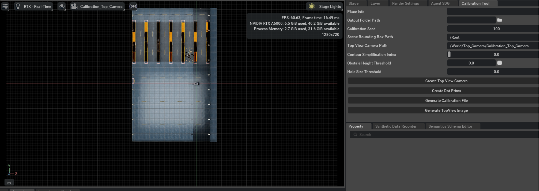
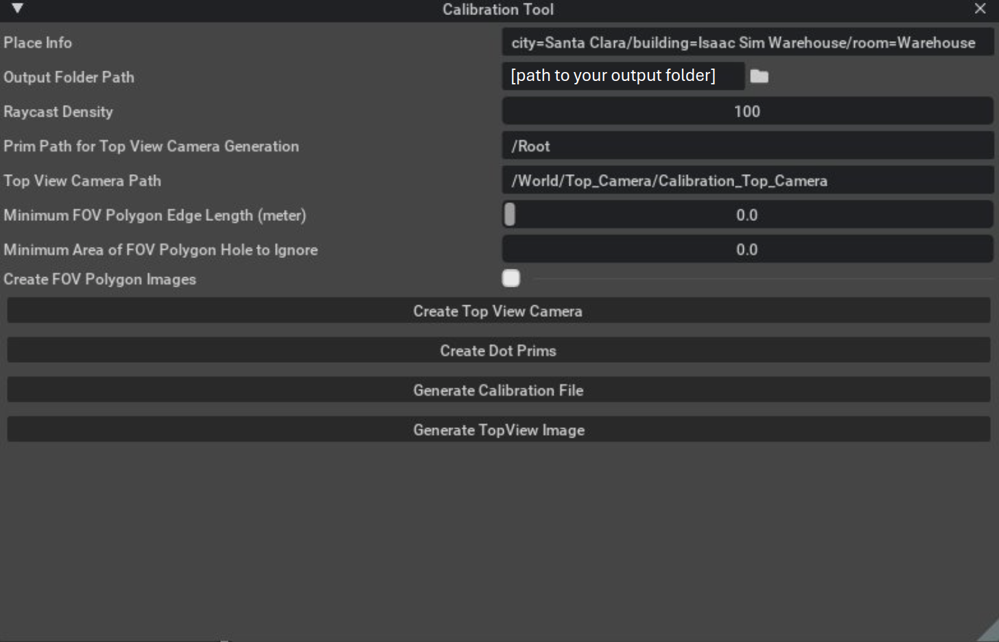
Calibration Tool Components#
UI Layout#
Input Fields#
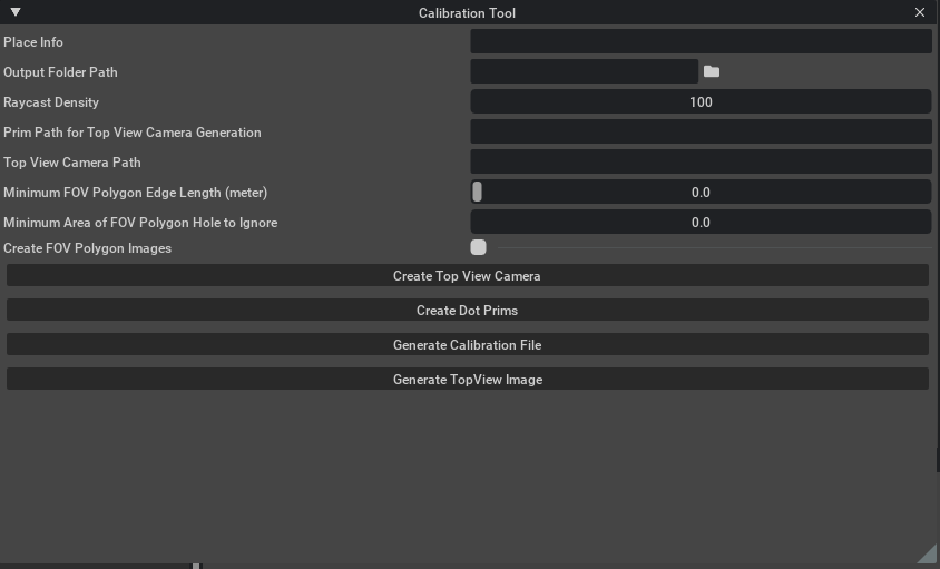
Place Info
Usage: Define place info in this field. Input is converted and recorded in the
calibration.jsonfile generated from the extension.Default value: empty string
Input Format:
city=[city name]/building=[building name]/room=[room name]Example:
Input:
city=Santa Clara/building=NVIDIA Voyager/room=Visitor LobbyOutput: (in the calibration.json file)
{
    "place": [
        {
        "name": "city",
        "value": "Santa Clara"
        },
        {
            "name": "building",
            "value": "NVIDIA Voyager"
        },
        {
            "name": "room".
            "value": "Visitor Lobby"
        }
    ],
}
Output Folder Path
Usage: The address of the output information. Click on the folder icon to select the output folder address.
Default value: empty string
Raycast Density
Usage: The seed that affects the density of the ray cast. As you input a higher value in this field, it results in the generation providing a more detailed FOV contour. A seed value of
NindicatesN * N, which indicates that rays are uniformly distributed from each camera.Default value: 100
Prim Path for Top View Camera Generation
Usage: Get prim path of the root node of the scene to calculate the top-down camera’s position and rotation.
Default value: empty string
Top View Camera Path
Usage: Record the prim path of the top-view camera. The view port of the top view camera is used to generate the top_view image.
Default value: empty string
Notice
The Top View Camera must be vertical to the ground and it must cover the position of all the calibration dots under the World/Calibration_Dots prim path and cameras under the World/Cameras prim path. Validate that the Top View Camera has a rotation [0,0,0] with projection set to “orthographic”.
The Top View Camera must be 1080P
Minimum FOV Polygon Edge Length (meter)
Usage: Specify the minimum length of edges in the polygon’s contour. Edges shorter than this length are ignored, and the vertices are connected to the next point that meets this criteria.
Default value: 0 (no simplification)
Minimum Area of FOV Polygon Hole to Ignore
Usage: When generating data, disregard holes in the FOV polygon that are smaller than this threshold value. Holes are the areas that are not included in the FOV polygon.
Default value: 0 (maintain every hole on the FOV polygons)
Create FOV Polygon Images
Usage: When generating top view image, render top view image with FOV polygon in debug data folder.
Default value: False (Do not generate the debug images)
Prerequisites#
Before generating the calibration.json file and generating the top view image, you must meet the following prerequisites (or an error message is thrown):
Top View Camera Path field is set up with a valid camera prim path, and the top view camera must be an orthographic projection camera with rotation [0,0,0].
The output folder path value is not empty.
The Place Info must be added and have the correct format.
To generate a calibration file for any camera, the camera must be set in the
/World/Camerasprim path.
Walkthrough#
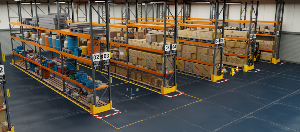
Here is a walk-through example that uses the calibration extension to generate camera calibration information. The Isaac Sim Full Warehouse: (.../Isaac/Environments/Simple_Warehouse/full_warehouse.usd) is used as the example scene. The following is an image of the environment:
Note
Stage unit must be in meters.
Make sure that there is a valid navmesh volume in the stage and that the navmesh only covers accessible areas.
Step 1#
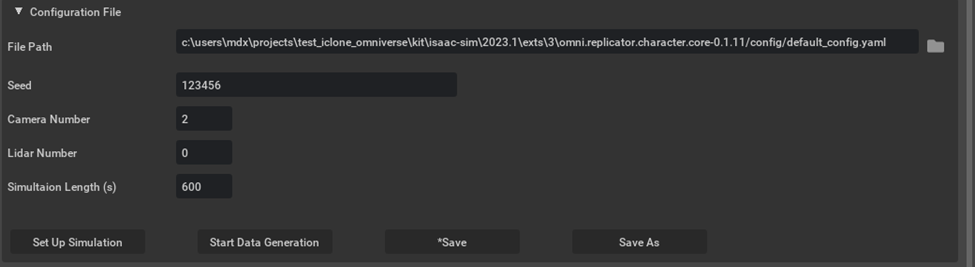
Add two cameras to the /World/Cameras path as sample cameras. Ideally, adjust the camera’s position so that their view extends from the top to the ground.
You can use the people SDG panel by adjusting the Seed, setting Camera Number to 2, and clicking on Set Up Simulation to automatically generate two cameras in the Warehouse Scene.
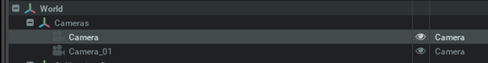
Alternatively, you can create cameras and the /World/Cameras Xform manually. This would be the hierarchy of the camera prims inside the stage.
Tip
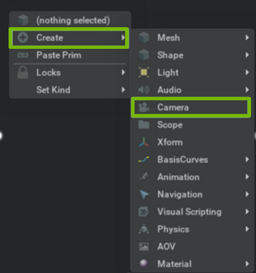
To create a camera in the stage manually, right-click the stage panel and then click Create > Camera.
Step 2#
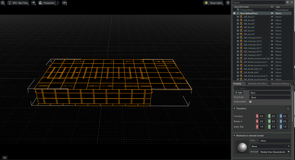
This step is about generating a top view with “orthographic projection” camera and “section tool” extension.
Adjust the perspective camera’s height and view the scene from a far position.
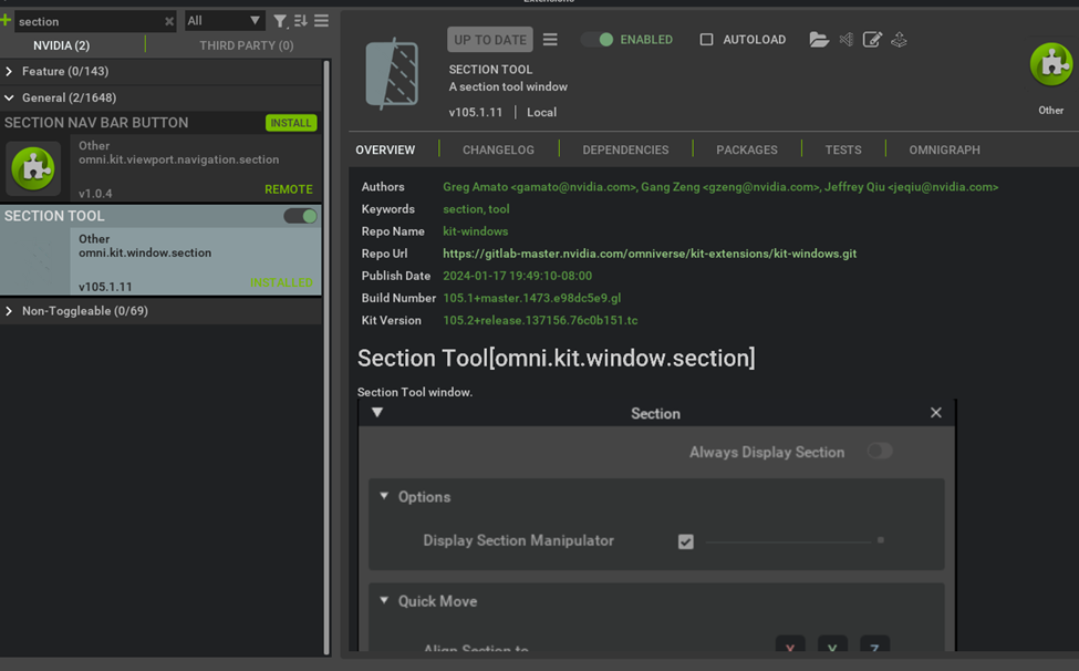
Search “Section” in the Window > Extension UI and enable the Section Tool Extension.
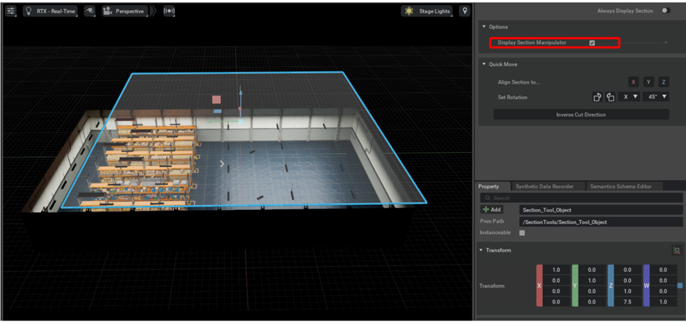
Navigate to the Section option located under the Tools menu. Click on the button to open the Section panel.
The “section tool” extension uses a horizontal plane to slice your scene.
To create an optimal top view we would need to exclude objects like the ceiling, manipulate the transform of the plane
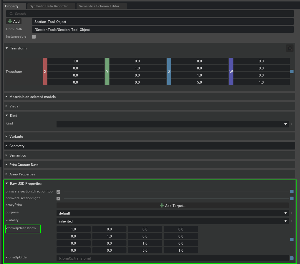
/SectionTools/Section_Tool_Object.
Note
To manipulate the transform of the plane, adjust the xformOp:transform directly in Raw USD Properties under the Property Panel. You can safely ignore any error messages.
Uncheck Options > Display Section Manipulator to hide the plane after an ideal top view is generated.
Add an orthographic projection top view camera to capture our top view image.
To add a camera on the stage as the top view camera, set
Prim Path for Top View Camera Generationto/Root, then click Create Top View Camera.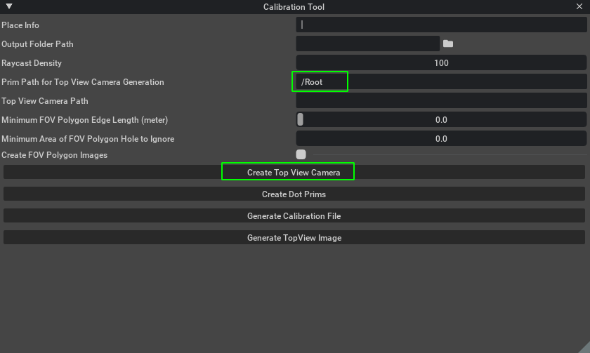
The
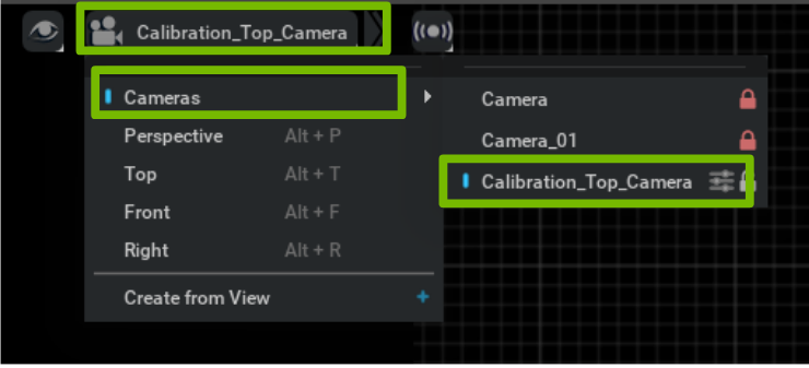
Top View Camera Pathis set automatically. You can then switch the viewport to top view camera.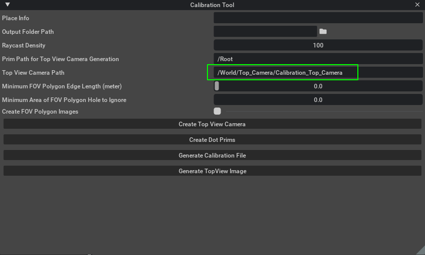
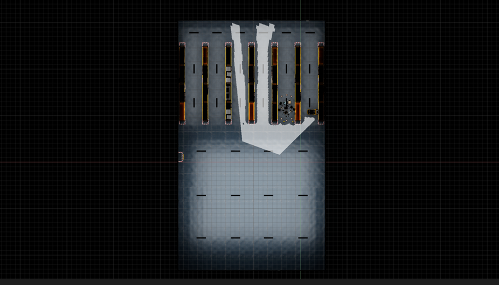
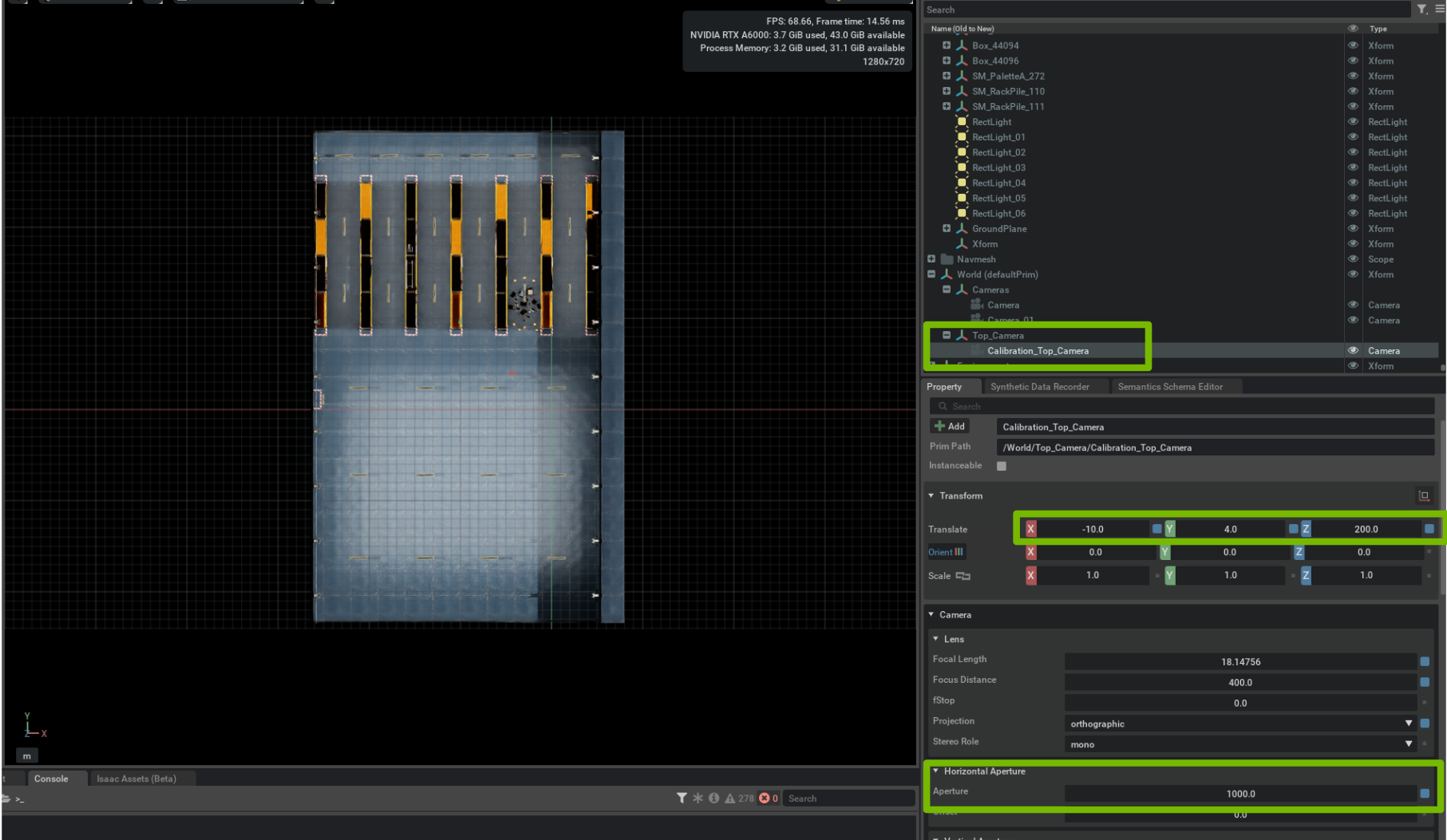
Verify that your view is similar to this after switching the viewport to the top view camera:
Tip
To switch the viewport to the top-view camera, click the Camera Icon, then click the Calibration_Top_Camera camera.
Adjust your viewport to 1080P, then change the Translate and Horizontal Aperture settings of the camera until it covers the entire scene.
Tip
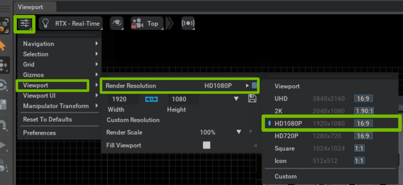
To change the viewport to 1080P, click Settings > viewport > Render Resolution > HD1080P.
Step 3#
Input the scene information in the Calibration Tool panel:
Input the place information in Place Info following the format:
For example,
city=Santa Clara/building=Isaac Sim Warehouse/room=Warehouse
Select the output folder path by clicking on the folder icon.
Input the Calibration Seed, where the ideal range is 100 - 250. A higher value generates a more accurate FOV polygon.
Input the top camera path into the Top View Camera Path field.
For example,
/World/Top_Camera/Calibration_Top_Camera
Step 4#
Generate Calibration Dots for each Camera by clicking on the Create Dot Prims button.
Calibration dot prims are generated under /World/Calibration_Dots prim.
For each Camera prim under /World/Cameras, six calibration dots are generated. Those Xform prims are used to calculate the projection matrix for each camera.
All calibration dots are categorized under a parent prim that is named according to their target camera.
Note
You can switch your viewport to an arbitrary camera’s view to check whether all the calibration dots are visible.
Step 5#
Generate a sample calibration file by clicking on Generate Calibration File button. This generates a
calibration.jsonfile at your output folder location.After the
calibration.jsonfile is generated. You can visualize the FOV in the stage by selecting your target camera.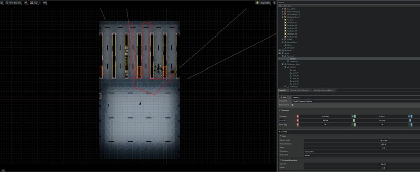
Step 6#
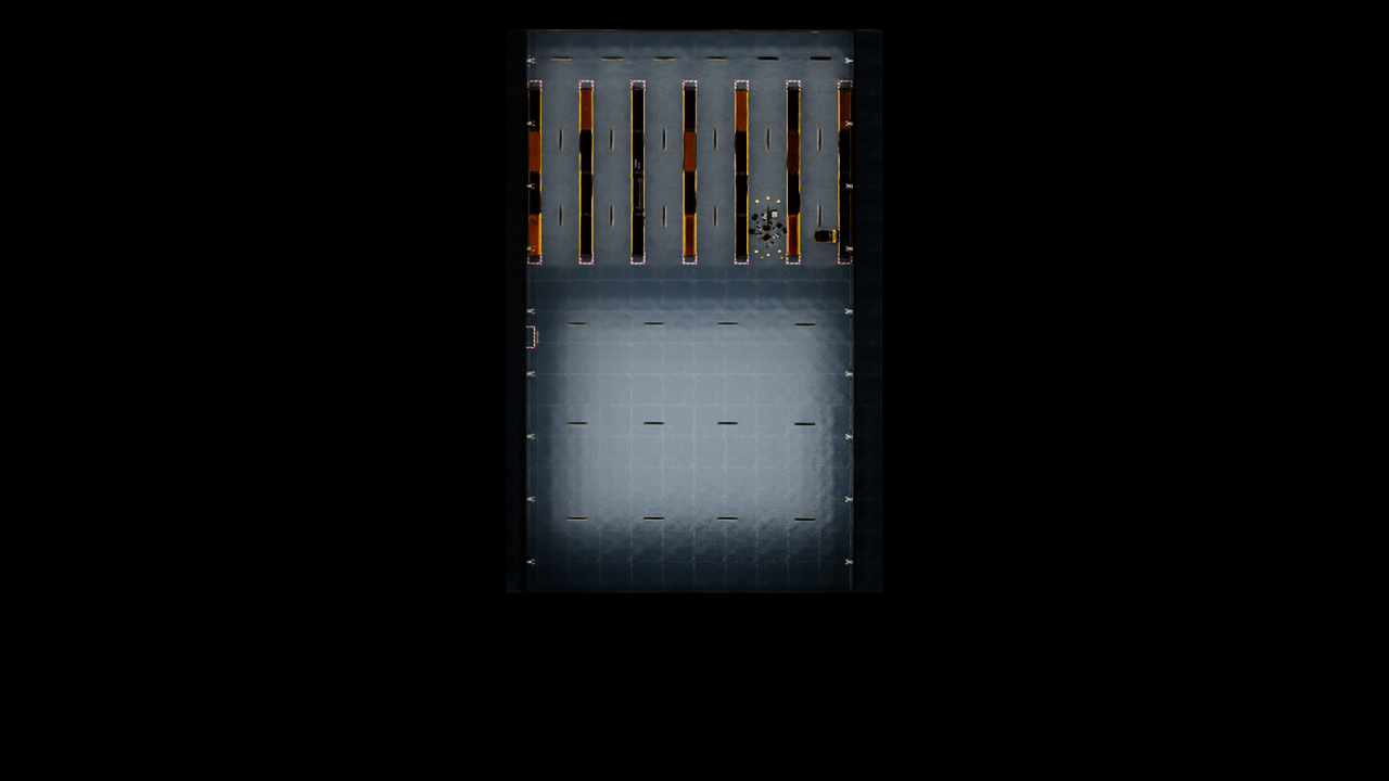
To visualize the generated FOV polygon top view image, generate the image by clicking on Generate TopView Image button.
The Top View Camera’s view would be rendered and output in the result folder. An``imageMetadata.json`` file is also generated to record image information.
Note
If Create FOV Polygon Images is checked, for each camera, the FOV is recorded as a semi-transparent white FOV polygon on the top view image.
The FOV polygon images would generated under [your output folder path]/Debug/fieldOfViewPolygon.