RTX Lidar Nodes
There are several RTX Lidar specific nodes. They can be used on the RtxSensorCpu AOV that is output from the sensor camera created with the IsaacSensorCreateRtxLidar command.
This section describes the nodes, and any input parameters that can control them, and lists the synthetic data writers that use them. For an explanation of their output, see their corresponding Annotators.
Compute RTX Lidar Flat Scan Node
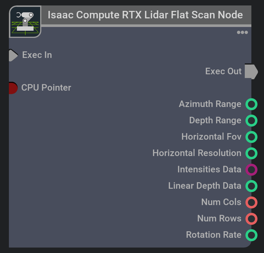
This node holds a full buffer of returns from a lidar. It’s designed for use with 2D Lidar (e.g. see the SLAMTEC’s RPLidar S2E Lidar in our RTX Lidar Config Library), but can
be used with any rotary or solid state Lidar configuration. The node accumulates, then outputs, intensity and range data buffers from one full Lidar scan.
The emitter used will be the one with the minimum magnitude elevationDeg value in its Emitter State Parameters, and the lowest index.
first Lidar scan may be a partial scan if first rendered beam is not at the minimum azimuth for the scan; note for rotary Lidars, azimuth is reported in range [-180, 180]
degrees. This node will not filter out invalid scans, meaning points with range below 0.0 may be returned.
The Compute RTX Lidar Flat Scan node is designed to output data for ROS/ROS2 LaserScan messages. There are examples of its use in
the RTX Lidar Sensors and RTX Lidar Sensors tutorials. You can also see examples of
its use if you run the standalone examples:
./python.sh standalone_examples/api/omni.isaac.ros_bridge/rtx_lidar.py
./python.sh standalone_examples/api/omni.isaac.ros2_bridge/rtx_lidar.py
There are no input parameters to control this node’s output.
The annotator that creates this node is RtxSensorCpuIsaacComputeRTXLidarFlatScan.
There are no Writers for this node.
Compute RTX Lidar Point Cloud Node
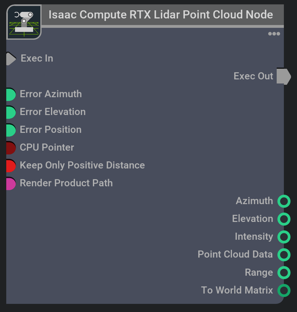
This nodes takes the per frame data from the sensor and creates a point cloud from it. It outputs every rendering frame, and does not wait for the Hz of the lidar. The point cloud data computed form this node is output in the ISO 8855 standard in the coordinate system of the sensor. The transform output can transform that point cloud to world coordinates for easy viewing in the scene. The Render Product Path should be from the same render product that the RtxSensorCpu buffer came from.
The RTX Lidar can output many points that have invalid returns, so using the Keep Only Positive Distance parameter will do as it says, and keep only distances that are greater than 0. Be warned that when using it, the number of points may be a lot lower, and that number will also likely change from frame to frame.
The three error parameters are designed to mimic Lidar accuracy error, and are applied to all output points equally.
This node is designed to go in concert with the Read RTX Lidar Data Node, and if you want the data from both nodes to have the same array index, then the value of Keep Only Positive Distance must be the same on both.
The annotator that creates this node is RtxSensorCpuIsaacComputeRTXLidarPointCloud.
The RtxLidarDebugDrawPointCloud Writer displays the points output in data in the current stage.
Print RTX Lidar Print Info Node
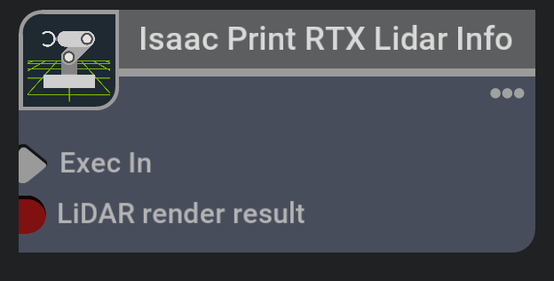
This node is a special case node. It is written in python, and designed as an example for users to reference and create their own OmniGraph nodes. It shows much of the structure of the RtxSensorCpu buffer, and prints out some information stored in it to the console.
Its code is located in the ./exts/omni.isaac.sensor/omni/isaac/sensor/ogn/nodes folder.
The WriterIsaacPrintRTXLidarInfo Writer can be used to create this node, and will output to stdout unless the testMode input is \(True\).
Read RTX Lidar Data Node
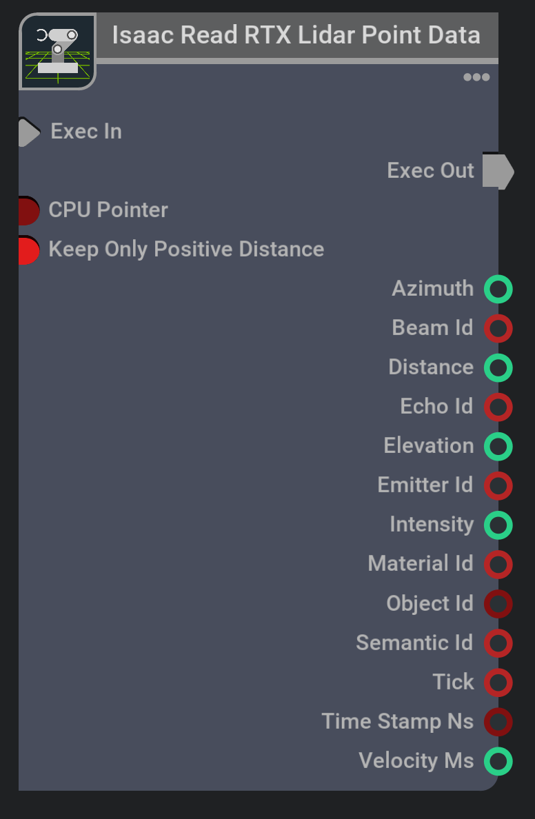
This node copies the per frame data from RtxSensorCpu and output it as contiguous arrays. Other than being copied, the data is not altered in any way.
This node is designed to go in concert with the Compute RTX Lidar Point Cloud Node, and if you want the data from both nodes to have the same array index, then the value of Keep Only Positive Distance must be the same on both.
The annotator that creates this node is RtxSensorCpuIsaacReadRTXLidarData.
The WriterIsaacReadRTXLidarData Writer can be used to create this node.
Create RTX Lidar Scan Buffer
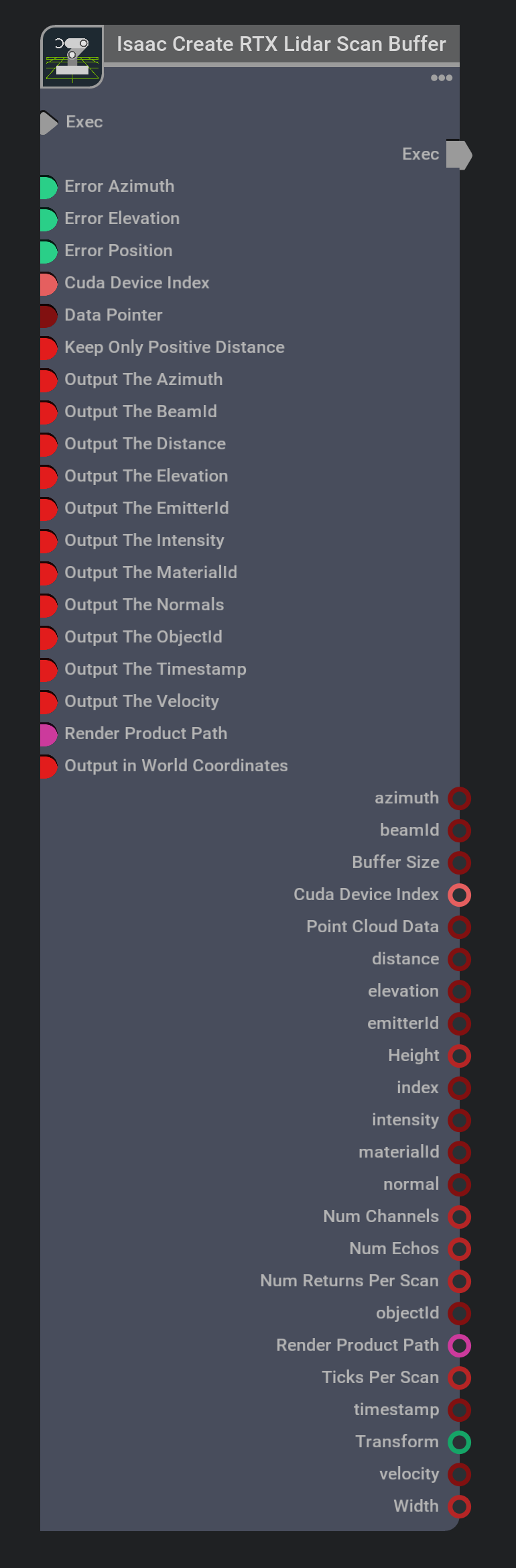
This node creates a buffer containing one full scan of Lidar returns. All the firings from a full rotation for rotary Lidar, and one complete firing of all the emitters in a solid state lidar. The point cloud data computed form this node is output in the ISO 8855 standard in the coordinate system of the sensor. The Render Product Path should be from the same render product that the RtxSensorCpu buffer came from.
There are several input parameters that control the output of this node.
The outputFoo check boxes, where Foo is any output parameter, allow the user to decide which outputs are actually created, because not all applications will need every output. The point cloud is always created and passed out the data output, and by default, the intensity and distance are also output.
The three error parameters are designed to mimic Lidar accuracy error, and are applied to all output points equally.
The transformPoints setting is true by default, so the points will be transformed to the correct world coordinates. If you decide to not use this output, the points will be output in the sensor coordinates.
Warning
If you do not use transformPoints, and you decide to use the transform output to visualize the points in world coordinates, then be aware that only the most recent transform is output. That means that points in the buffer that are older will be getting a newer transform then the one they should have.
The RTX Lidar can output many points that have invalid returns, so using the Keep Only Positive Distance parameter will do as it says, and keep only distances that are greater than 0. Be warned that when using it, the number of points may be a lot lower, but that number will also likely change from frame to frame.
Note
When using Keep Only Positive Distance, the indices into the original buffer will be output for each return. From this index, you can get the tick, the emitter, and the echo for each return.
The maximum number of possible returns in a scan is output as numReturnsPerScan, which is a bit redundant because \(numReturnsPerScan=ticksPerScan \times numChannels \times numEchos\)
where ticksPerScan is the maximum number of ticks per scan, numChannels is the maximum number of firings per tick and numEchos is the maximum number of returns per firing as set
by the maxReturns configuration parameter.
With the above constants you can calculate the tick, channel and echo of a return from it’s index output, \(i\), with the following equations
\(tick = \frac{i}{numChannels \times numEchos}\).
\(channel = \frac{i-tick \times numChannels \times numEchos}{numEchos}\).
\(echo = i \bmod numEchos\)
The annotator that creates this node is RtxSensorCpuIsaacCreateRTXLidarScanBuffer.
The RtxLidarDebugDrawPointCloudBuffer Writer displays the points output in data in the current stage.