Assemble a Simple Robot#
Omniverse Isaac Sim’s GUI interface features are the same ones used in NVIDIA Omniverse™ USD Composer, an application dedicated to world-building. In this tutorial series, we will focus on the GUI functions that are most relevant to robotic uses. For more sophisticated general world creation, please check out Omniverse Composer.
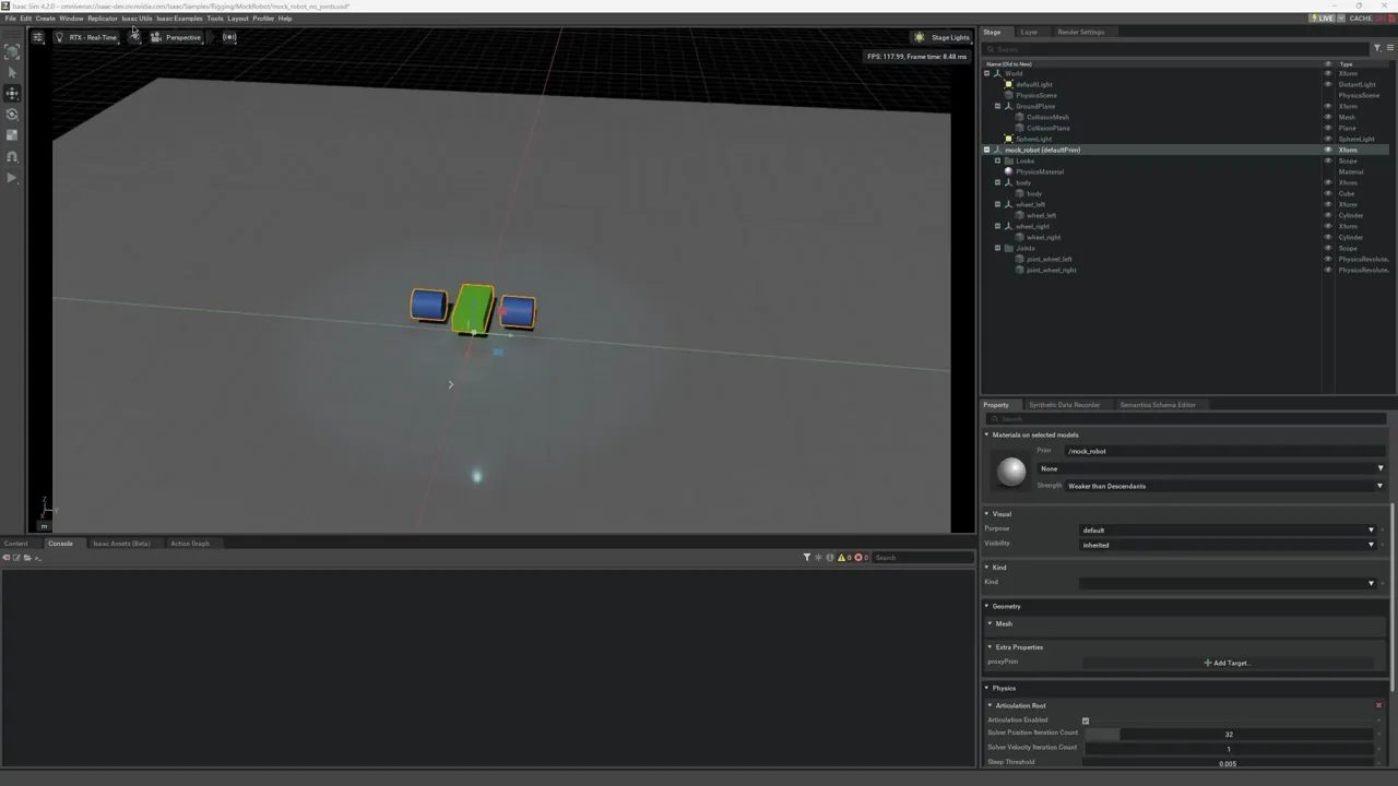
In this tutorial, we will rig a simple “robot” with three links and two revolute joints to introduce the basic concepts of joints and articulations. We will take the objects that were added to the stage in Add Simple Objects, and turn them into a mock mobile robot with rectangular body and two cylindrical wheels. While this step is not needed for robots that are imported from Importing your Onshape Document or URDF Importer, these are important concepts to understand for tuning your robots and assembling objects with articulations.
Learning Objectives#
This tutorial details how to rig a two-wheel mobile robot and covers how to:
Organize stage tree hierarchy
Add joints between two rigid bodies
Add joint drives and joint properties
Add articulations
Move the robot via a Articulation Velocity Controller
Getting Started#
Prerequisites
Complete all Introductory Tutorials.
Add Joints#
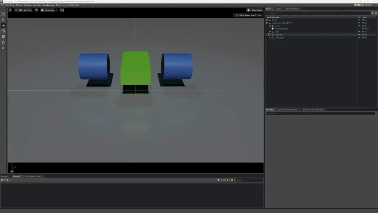
If you are continuing from the Introductory Tutorials and have your own mock_robot.usd saved, open it using File> Open. Otherwise, load the asset provided in Isaac/Samples/Rigging/MockRobot/mock_robot_no_joints.usd. Do not load it as a reference because you must make permanent modifications to the file.
For organization, create a Scope to store the joints by right clicking Create > Scope
To add a joint between two bodies, click on the parent body and then the child body. For our mock robot, select
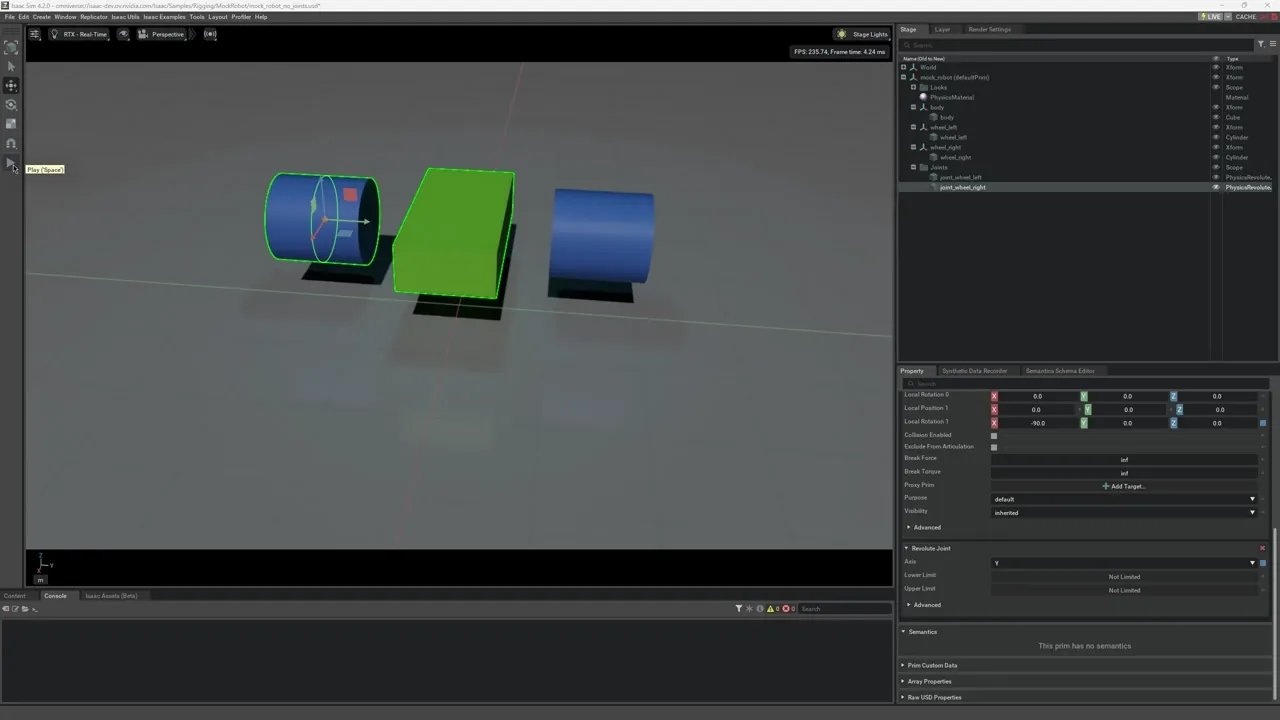
body, then while holdingCtrl + Shift, selectwheel_left. With both bodies highlighted, right-click and select Create > Physics > Joints > Revolute Joint.RevoluteJointappears underwheel_lefton the stage tree. Rename it towheel_joint_left.Verify in the Property tab that body0 is
/mock_robot/body(the cube) and body1 is/mock_robot/wheel_left(the cylinder).Change the Axis of the joint to Y.
If you look closely, the joint’s two local frames are misaligned. To correct it, go to Local Rotation 0 and make x = 0 degrees. Next, go to Local Rotation 1 and make x = -90 degrees. The example here only shows an orientation misalignment, you may see translational misalignment depending on your robot.
Repeat steps 1-4 for the right wheel joint.
Before the joints were added, the three rigid bodies fell to the ground separately after pressing Play. Now that there are joints attached, the bodies fall as if they are connected.
To see that they move together like they are connected via revolute joints, you can drag the robot around by holding down the Shift key and clicking and dragging on any part of the robot in the viewport.
Add a Joint Drive#
Adding the joint adds the mechanical connection. To be able to control and drive the joints, you must add a joint drive API.
Select both joints and click the + Add button in the Property tab, and select Physics > Angular Drive to add drive to both joints simultaneously.
Position Control: For position controlled joints, set a high stiffness and relatively low or zero damping.
Velocity Control: For velocity controller joints, set a high damping and zero stiffness.
For joints on a wheel, it makes more sense to be velocity controlled, so set both wheels’ Damping to 1e4*and *Target Velocity to 200. If you are working with joints with limited range, those can be set in the Property tab, under the Raw USD Properties > Lower (Upper) Limit. Press Play to see the mock mobile robot drive off.
Add Articulation#
Even though directly driving the joints can move the robot, it is not the most computationally efficient way. Making things into articulations can achieve higher simulation fidelity, fewer joint errors, and can handle larger mass ratios between the jointed bodies. For more information on the physics simulation behind it, see Physics Core: Articulation. To turn a series of connected rigid bodies and joints into articulation, set an articulation root to anchor the articulation tree. According to instructions on defining articulation trees in Physics Core: Articulation:
For a fixed-base articulation, add the Articulation Root Component either to: 1) the fixed joint that connects the articulation base to the world, or 2) an ancestor of the fixed joint in the USD hierarchy. The second option allows creating multiple articulations from a single root component added to the scene. Each descendant fixed joint defines an articulation base link. For a floating-base articulation, add the Articulation Root Component either to: 1) the root rigid-body link or 2) an ancestor of the root link in the USD hierarchy.
For this tutorial, add the articulation root to the robot:
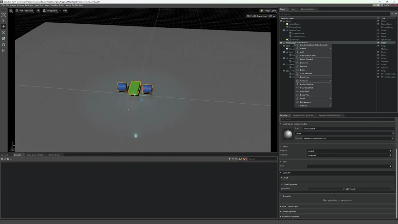
Select
mock_roboton the tree.Open + Add in the Property tab.
Add Physics > Articulation Root.
Validate that the resulting robot matches the asset that is provided in Isaac/Samples/Rigging/MockRobot/mock_robot_rigged.usd.
Add Controller#
After the joints are part of an articulation, you can use tools to test the robot’s movement.
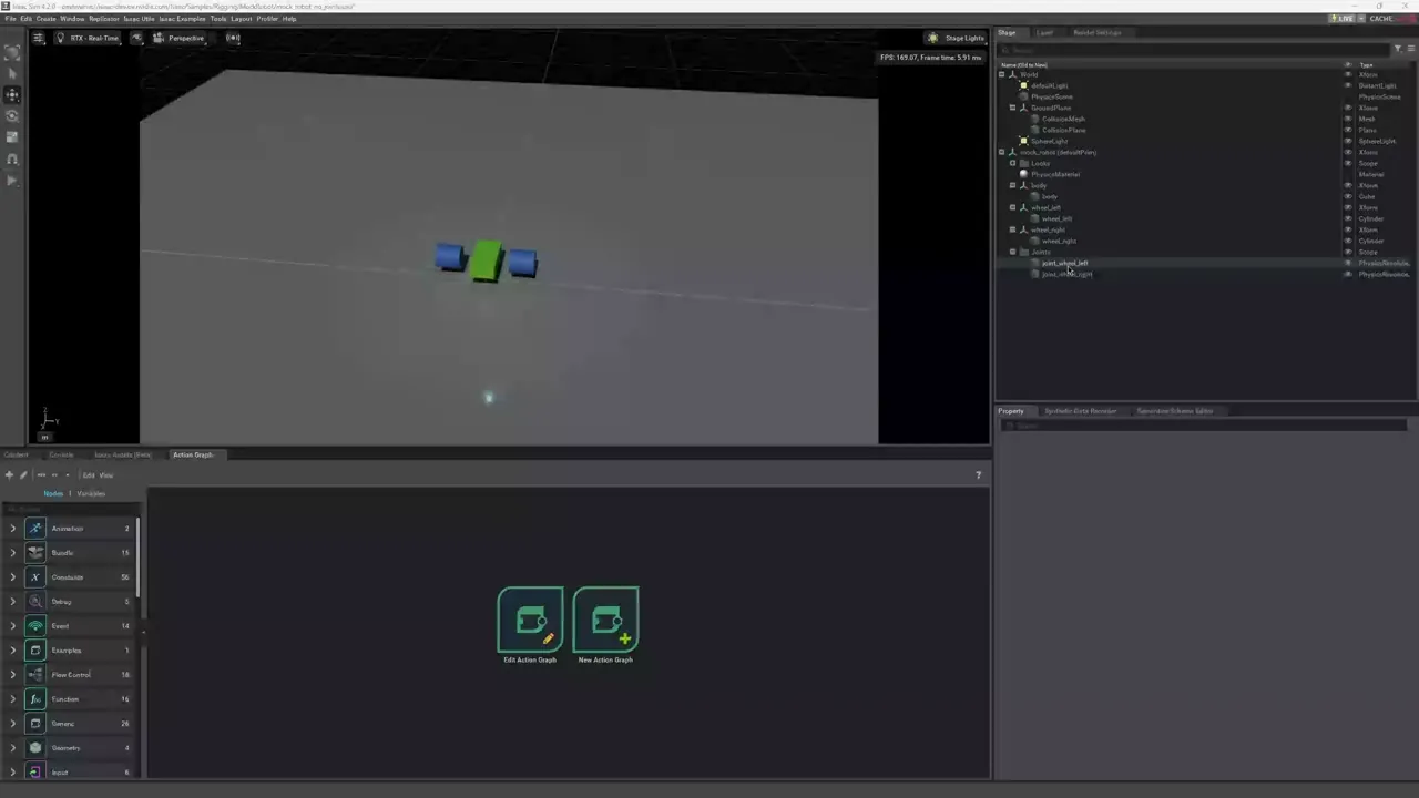
Go to Isaac Utils > Common Omnigraphs and add a “Articulation Velocity Control” Graph. This graph allows you to control the robot’s movement by setting the target velocity for each joint.
You are prompted for the necessary parameters. Click the Add button for “Articulation Root” and select the prim with the Articulation Root API, in this case, it’s /mock_robot/body.
Because the Articulation Root API for this robot is not the same as the robot’s root prim, you must add the “Robot Root” parameter. In this case, /mock_robot.
Click OK to create the graph.
To move the robot, press Play to start the simulation. If you have any default position or velocity targets set, the robot starts moving towards those targets immediately. To change the joint commands, highlight the JointCommandArray on the stage tree under /World/Graphs/articulation_velocity_controller{_n}/JointCommandArray, and change the joint angles in the Property Manager Tab -> Raw USD Properties.
Note
The articulation controllers use radians, the default USD properties you find under Drive API when you select the individual joints on the stage tree are in degrees.
For this particular robot, it can also be controlled using a Differential Controller. For more information about Omnigraph Controller shortcuts, go to Commonly Used Omnigraph Shortcuts.
Summary#
In this tutorial, you learned to connect rigid bodies using joints, add a joint drive to control the joints, turn a chain of joints into an articulation, and control the robot using an Articulation Velocity Controller.
Next Steps#
Continue on to Add Camera and Sensors to learn how to add a camera to the car.
Further Reading#
Physics Core for more details regarding joints and articulations.