Rigging Robots#
If you built a robot inside Omniverse USD Composer or used importers that do not carry over joint information, you’ll need to rig the robot before it can move like an articulated robot and be controlled by Isaac Sim APIs. This involves defining the types of joints between the body parts and setting the parameters that governs the joints’ behavior, such as stiffness and damping. This tutorial covers step-by-step instruction on how to rig a forklift.
Learning Objectives#
In this tutorial, an unrigged forklift USD asset is turned into a forklift that can move and be driven by Isaac Sim commands.
Getting Started#
Prerequisite
Complete the Introductory Tutorial Series series to learn the basic core concepts of how to navigate inside Isaac Sim.
Complete the Assemble a Simple Robots and Adding Sensors and Cameras tutorials to learn the concepts of rigid body API, collision API, joints, drives, and articulations.
Reference USDs
We provide three USD assets relating to this tutorial in sample assets:
Unrigged Forklift:
Isaac/Samples/Rigging/Forklift/forklift_b_unrigged_cm.usdRigged Forklift:
Isaac/Samples/Rigging/Forklift/forklift_b_rigged_cm.usd
This tutorial guides you through the steps for going from file to file. The rigged assets serve as a reference for the final goal.
Rigging the Robot#
Identify the Joints#
Before making any modifications to the asset, the first step of rigging a robot is to identify the joints on the robot, both actuated and unactuated ones. The joints govern how all the mesh components are organized, and identifying the type and their degrees of freedom (DOF) are key in making sure the robot moves as expected once rigged.
For the forklift, there are 7 DOF in total:
There are 4 smaller roller wheels at the front. They have unactuated, revolute joints, and each has one degree of freedom for rotation about a single axis.
The fork has linear motion relative to the main body of the forklift as it moves up and down to pick up objects stacked on the pellet, which means there is one actuated, prismatic joint between the fork and the body.
The bigger wheel at the rear end is responsible for propelling the forklift and turning it. There are two actuated joints related to this wheel:
A revolute joint that spins the wheel around its central axis to provide the forward and backward movement.
A revolute joint between the rear wheelbase and the forklift body that provides the pivot to turn the forklift.
Organize the Hierarchy#
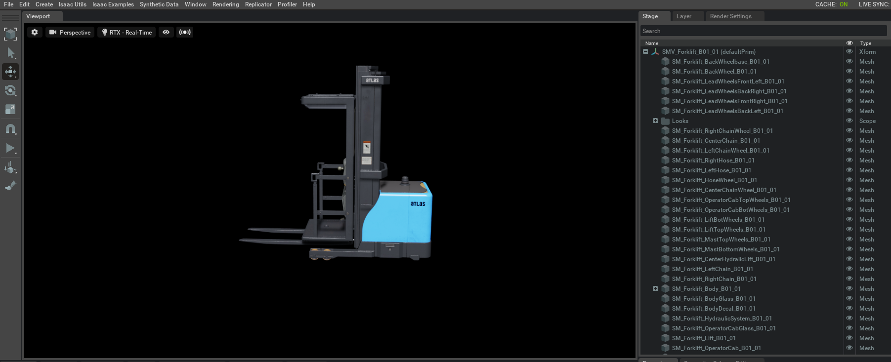
Open the unrigged forklift asset Isaac/Samples/Rigging/Forklift/forklift_b_unrigged_cm.usd.
Depending on the importer used and the original asset’s setup, the unrigged structure of the USD could have no hierarchy in terms of how parts are organized. It could have every single component listed independently on the stage tree. This makes it difficult to read and navigate, but more importantly, it does not define which objects are moving as a group and how these groups are related to each other.
All meshes that are children of a parent prim are expected to move together when the parent prim moves. For example, the sticker and chains on the meshes are a part of the forklift body, and the entire body, no matter how many screws or blocks are used to make up the body, can be considered as a single link of this robot. Organize them all under a single parent ‘body’ prim. This ensures that when the ‘body’ moves, that all child parts that make up the body are moving together.
To organize prims for the forklift:
Create two XForms called ‘body’ and ‘lift’.
Move all the meshes that make up the forklift body under the ‘body’ Xform, and the operator cab meshes under the ‘lift’ Xform. For ease of use, the meshes provided in the USD file are sorted according to their hierarchy. All meshes above ‘Looks’ are a part of the ‘lift’ XForm. Meshes below ‘Looks’ (Right Chain Wheel to Body Glass) are a part of the ‘body’ XForm. Remaining are for the wheelbase and wheels.
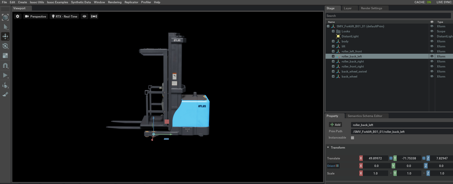
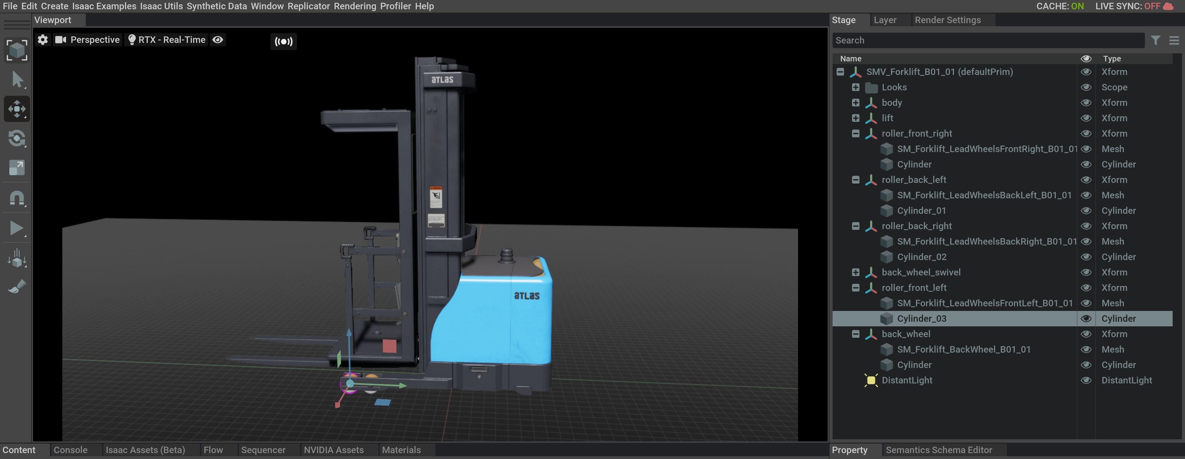
Create new Xforms for the back wheel, back wheel swivel, and separate prims for each of the front roller supports.
It is easier to set the joints if they align the frame of the Xform to the frames of the respective wheels. To do so, for each wheel, select the mesh, and in its property tab under Transform, there are two components
TranslateandTranslate:pivot. The newly created Xform’s transform should be the sum of those two components. For example, iftranslateis attranslate:pivotis atTranslateof the wheel mesh needs to be set to the inverse of theTranslate:pivotproperty of the corresponding mesh. For example, ifTranslateisTranslate:pivotisMove the corresponding mesh under the XForm, this will define the parent-child relationship between them.
Verify that the resultant hierarchy looks like this:
Note
If you got stuck in this this section, review the Rigged Forklift: Isaac/Samples/Rigging/Forklift/forklift_b_rigged_cm.usd asset for reference.
Assign Collision Meshes#
The next step is ensuring that the collision properties are set correctly for the meshes. If no collision properties are set, then as the robot moves, it can self penetrate depending on the joint configuration.
The correct collision meshes for the body and the lift are already set for the USD provided, so you do not need to set them up manually. But for reference, the steps to set the collision for the SM_Forklift_Body_B01_01` are:
Select the
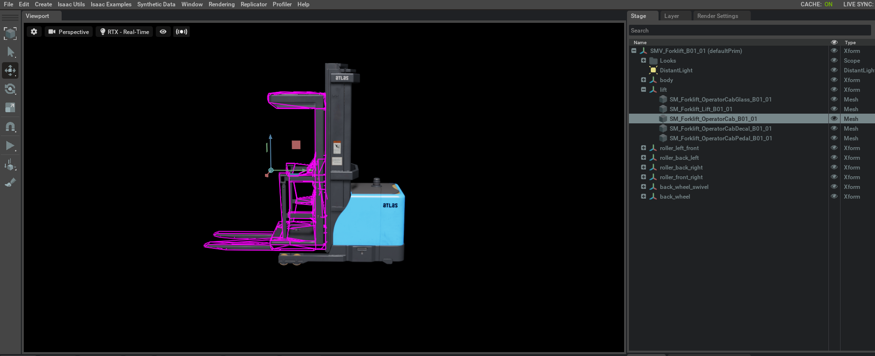
SM_Forklift_Body_B01_01mesh under theliftXform, right click and Add > Physics > Collider Preset. The default collision approximation is via Convex Hull which can be found when you scroll under the property tab for the mesh selected and find the collision section.To visualize the colliders, click on the ‘eye’ icon near the top right of the Viewport, select Show By Type > Physics > Colliders > Selected. Verify that you can see a Pink outline when you select the mesh that was just added to the collision. This approximation is not suitable as the collision region covers large areas that are not part of the fork and are regions that are necessary to allow other objects to exist.
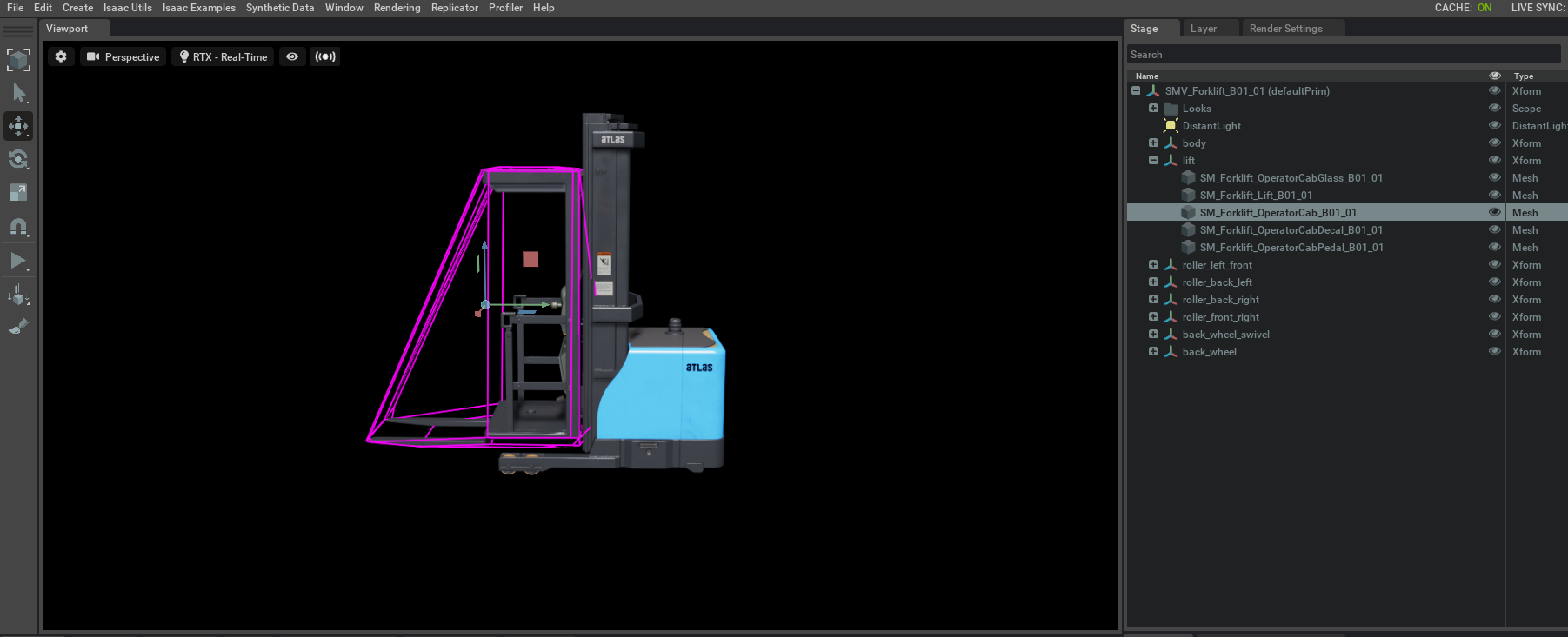
Different approximations can be used to define different collision meshes. To see this, select one of the meshes with a collision and navigate to the colliders section of its property pane. Select the Convex Decomposition approximation. Update the visualization for the collision mesh. Verify that the mesh generated, this time, covers more of the collidable surface because it has a tighter approximation. Try other approximations and to see what works best for you.
Follow the same process for other meshes that interact with each other via joints. Set the Convex Decomposition approximation for the SM_Forklift_BackWheelbase_B01_01` mesh that is a part of the swivel.
The process for the wheels is a little different, any collision approximation that is not smooth and captures the exact shape and curvature of the wheel causes bumpy motion when attempting to drive the wheel. This can be avoided by using a cylinder to approximate the collision mesh.
Go to Create > Shape > Cylinder.
Set the scale to X=0.16, Y=0.16, Z=0.08 and Orient along Y=90.
Right click and create 4 duplicates of this cylinder, one for each of the 4 front roller wheels.
Drag the cylinders under the respective wheel’s Xform and change their transform about all axes to 0. This aligns the cylinder axis and the Xform axis completely.
Right click on the cylinder and Add > Physics > Collider.
Following the same process for the back wheel, the cylinder scale should be modified to X=0.3, Y=0.3, Z=0.1, orient along Y=90 because of its bigger size.
Ensure that all Xforms have physics set to rigid body by clicking Add > Physics > Rigid Body. Remember rigid body prims cannot have children that are also rigid bodies.
All the appropriate collision meshes and properties are set up and you can move on to adding the joints.
Add Joints and Drives#
In this step, add appropriate joints for the Forklift.
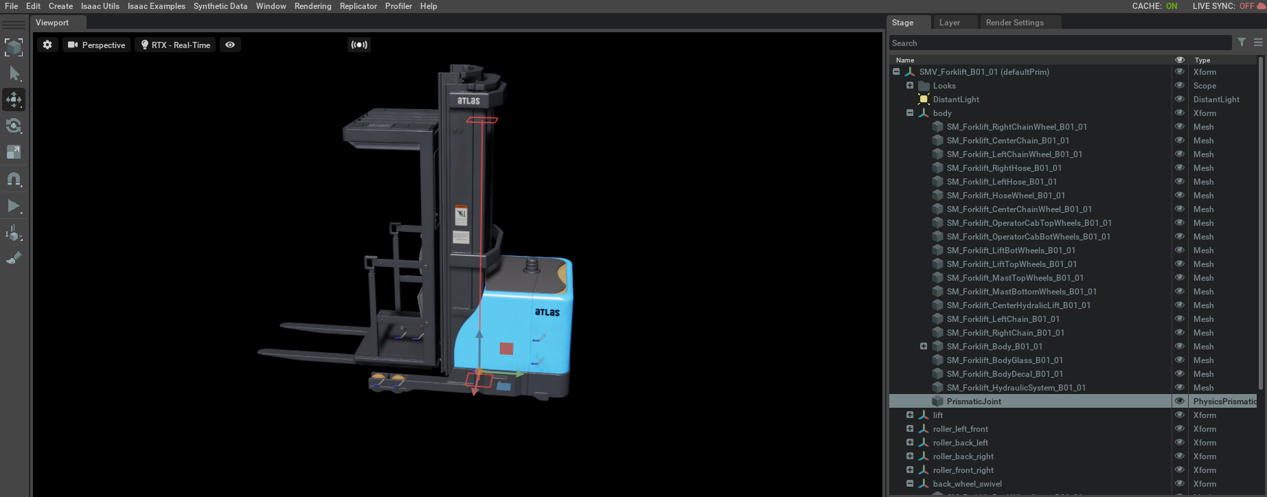
Prismatic Joint
The first joint is the joint between the forklift body and the fork. It needs linear motion between the two bodies, and the fork should move up and down relative to the body of the forklift.
Select the ‘lift’ Xform and while holding the Ctrl key select the ‘body’ Xform. While the two prims are highlighted, right click and Create > Physics > Joints > Prismatic Joint.
Find the newly created prismatic joint, select it. Under the properties tab, set the axis to ‘Z’ axis, this denotes that the linear motion between the two bodies is in along the Z-axis.
Set the limits for the joint in the Property tab, for now let’s set it to -15 and 200.
Add a Linear Drive for this joint by left clicking on the joint, and selecting Add > Physics > Linear Drive.
Set the Damping = 10000 and Stiffness to 100000. Set target position to -15 so that the fork can start its initial position close to the ground.
Revolute Joints
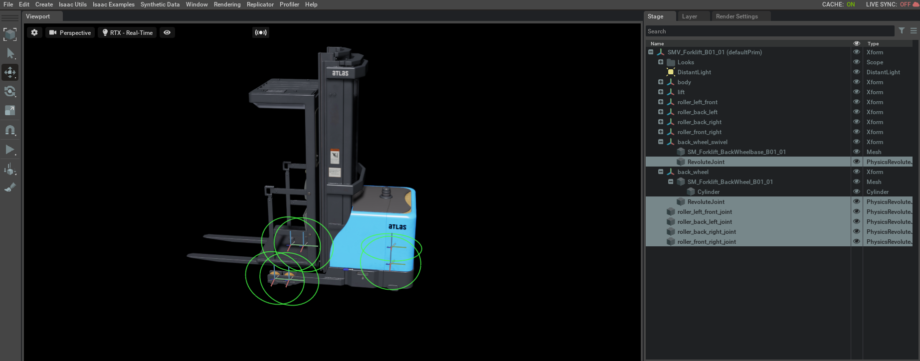
For all the roller support wheels, create revolute joints.
Select the ‘body’ XForm, holding the Ctrl key select any of the roller wheel XForms. Right click Create > Physics > Joint > Revolute Joint. Verify that you see a Revolute joint added under the Xform for the wheel.
Verify that the joints appear in the expected location. If not, make sure that the location of the joint matches the with the rotation axis of the wheel, and make sure to set the rotation axis to “X”.
Follow the same process for the three remaining roller supports of the forklift.
Next, add the last two joints, which are responsible for driving and turning the forklift.
Select the ‘back_wheel_swivel’ and ‘back_wheel’ XForms and add a revolute joint between them. The location of this joint should match with the center of the back wheel.
Add an angular drive to this joint with the following properties: Damping=10000, stiffness = 100.
Select the ‘body’ and ‘back_wheel_swivel’ XForm and add a revolute joint between them. Make sure the axis of rotation is set to
Z.Change the axis of the joint to Z axis and lower with upper limits as -60 and 60, because this joint enables turning of the forklift. This is the range of the angles in degrees that the wheelbase would rotate.
Add an angular drive with the following properties: Damping = 100, stiffness=100000.
Remember to add a Physics Scene and Ground Plane before pressing Play.
Add Articulations#
The last step is adding articulation to the Forklift and putting all the joints into a single articulation chain, which makes it easier for the physics solver when solving for articulated objects such as a robot. This has already been added for the prim in the reference USD assets. But if not, to put select and right click on the ‘SMV_Forklift_B01_01’ Xform and Add > Physics > Articulation Root. Under properties, disable the Self collision check box.
There are a few caveats for the placement of the articulation root.
If you place the articulation root on the root Xform prim of the asset, which is the standard for all Isaac Sim assets, then the simulation automatically assigns the articulation root to a rigid body in the robot, which minimizes the depth of the articulation tree.
However, if you want to manually determine the location of the articulation root, assign it to a rigid body component of the robot. It is recommended to place the articulation root on the base or the chassis of a mobile robot or the fixed joint on a robotics arm.
Verify that the asset you have is similar to the Rigged Forklift asset provided.
Converting Asset to a Different Unit#
The original asset is in centimeters. The asset is automatically converted to meters when it is added into a scene that is in meters (see Metrics Assembler). When the asset is added to a stage, it must match the Rigged Forklift in Meters asset provided.
You can now play around with the Forklift, set the back wheel velocity to -200 in the Angular Drive section for the joint. On hitting play, verify that you can see the forklift move forward.
Summary#
In this tutorial, we took an unrigged forklift USD asset, organized its structure, and added collision, joints, and drives, and turned it into a forklift that can move and driven by Isaac Sim commands.
Troubleshooting Tips#
If when playing the simulation or after some movements, your robot explodes, check if any of the collision meshes are colliding with each other.