Gain Tuner Extension#
About#
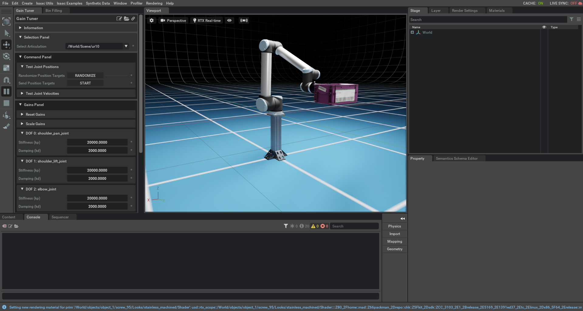
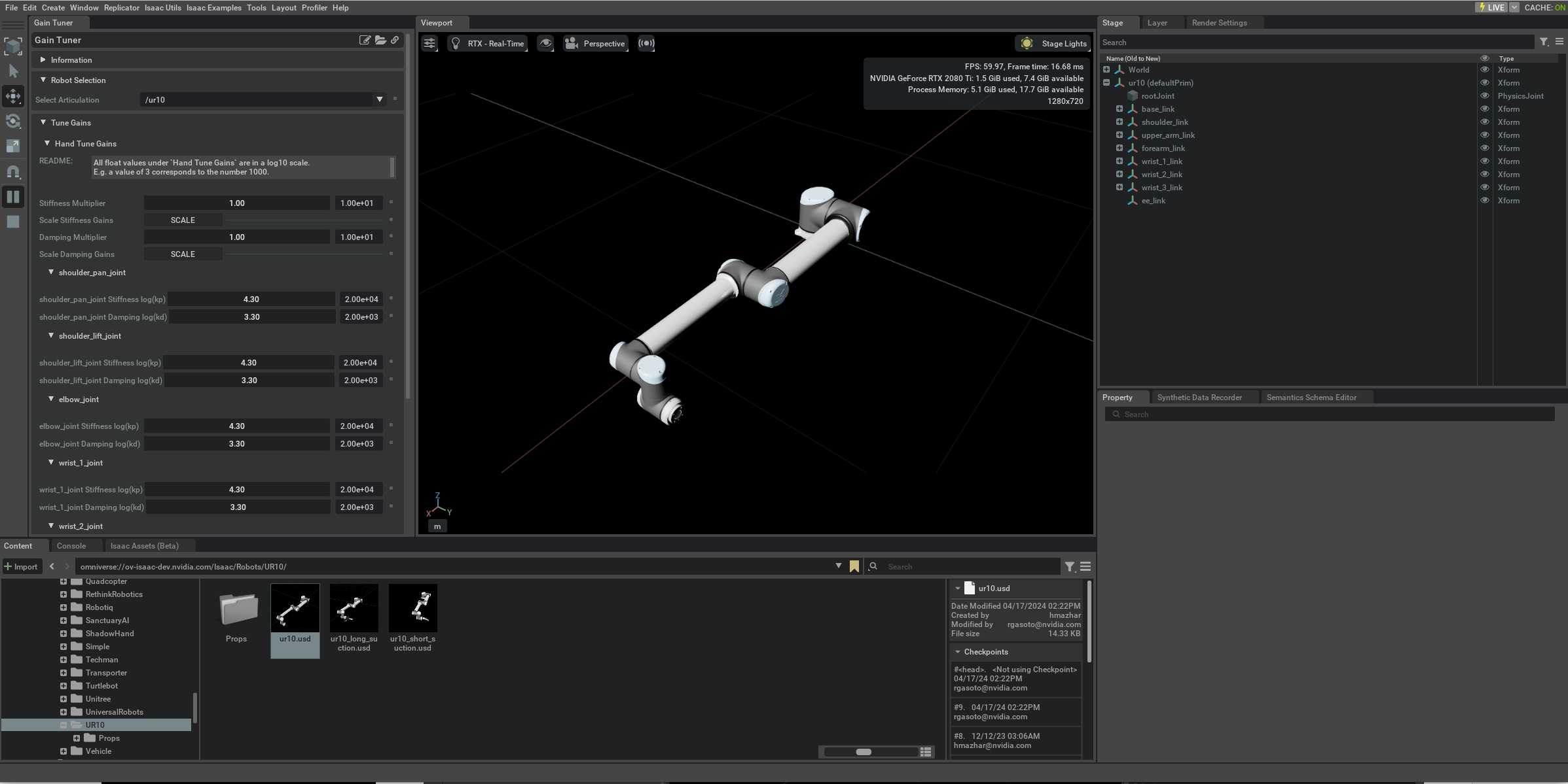
The Gain Tuner Extension is used to tune the stiffness and damping gains of a selected Articulation. This extension is useful when importing any new robot or when needing to fine tune the gains of an existing robot.
Note
The simulator must have been active for at least one step in order to inspect the selected articulation. Toggle the PLAY button, if in doubt.
This extension is enabled by default. If it is ever disabled, it can be re-enabled from the Extension Manager by searching for omni.isaac.gain_tuner.
To access this Extension, go to the top menu bar and click Isaac Utils > Workflows > Gain Tuner.
User Guide#
Overview#
The purpose of the Gain Tuner is to find a pair of stiffness and damping gains for each robot joint so that the robot is able to follow commanded trajectories with marginal error. The Gain Tuner offers a set of parameterized tests that allow the user to quickly assess the quality of the current set of gains as well as a utility for tuning gains by hand. This tutorial will take the user through
Sinusoidal Gains Test: A test that commands a continuous sinusoidal trajectory for each joint within the Articulation’s maximum velocities and accelerations.
Step Function Test: A test that commands a discontinuous joint target to check for qualitatively reasonable robot behavior.
Options For Tuning Gains: User options for tuning the gains for their robot.
Gains Test Settings: User parameters for the gains tests that allow a diverse set of ways to assess of how an Articulation’s gains affect its behavior.
Sinusoidal Gains Test#
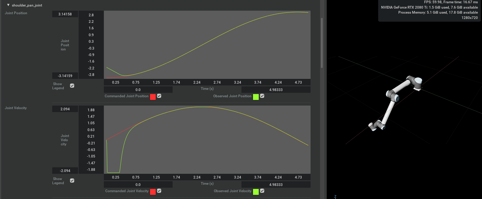
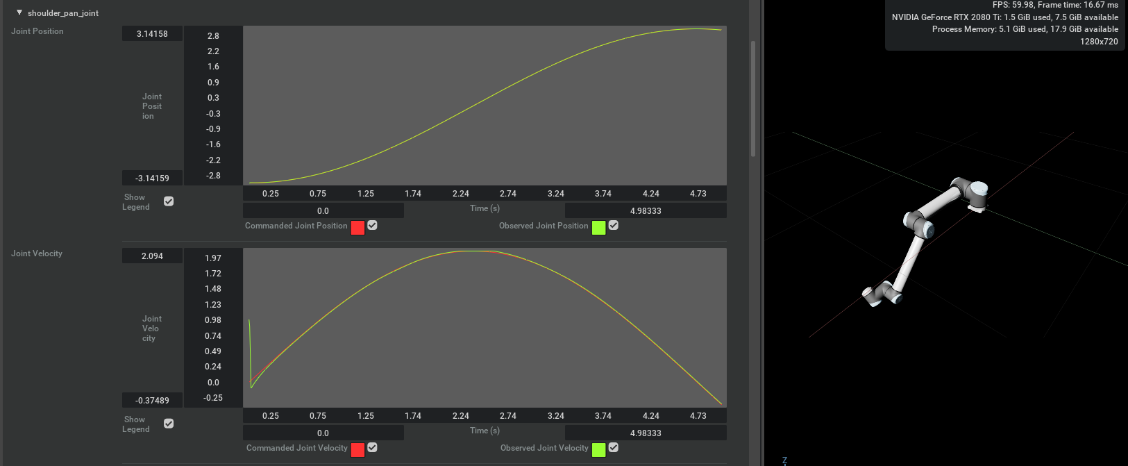
The Sinusoidal Gains Test sends sinusoidal trajectories to each robot joint that are continuous and consistent in both position and velocity. I.e. the integral of commanded velocities match the commanded positions. The output of the Sinusoidal Gains Test is a Root Mean Squared Error (RMSE) term for each joint’s commanded trajectory for both position and velocity tracking. A plot is generated for the position and velocity of each joint over the test duration.
The Sinusoidal Gains Test serves as a proxy for any continuous trajectory that can reasonably be sent to the Articulation. When sending a continuous trajectory to the robot, there are reasonable limitations on when the user can expect behavior to match commands.
Commanded velocity and position should be consistent with each other (Integrating velocity yields position).
Commanded velocity does not exceed the Articulation’s maximum acceleration or velocity parameters.
Commanded position should never exceed position limits, which implies that a position limit is never reached with a non-zero velocity.
The test parameters described in Gains Test Settings allow the user to thoroughly explore the behavior of their Articulation when following a continuous trajectory within the limitations listed above.
The figures below show the Sinusoidal Gains Test being run on the UR10 robot. The first figure has poorly tuned gains, and position and velocity tracking error is apparent in the resulting plots. The next figure shows the same asset achieving perfect tracking after clicking the “SET STIFF GAINS” button.
Poorly Tuned Gains#
Stiff Gains#
Step Function Test#
The Step Function Test sends discontinuous position commands to the Articulation and a velocity command of zero. In general this is not a pattern for robot control that should be applied in practice, as ideally the robot is only ever told to move continuously with consistent position and velocity commands. This test serves as a sanity check for generally reasonable behavior. Ideally, when the robot is commanded to a discontinuous position target, each joint will quickly reach its maximum velocity and the position graph will be mostly linear. The duration of the step function joint commands is a function of the Articulation’s maximum velocities. I.e. the commanded joint position stays high for a little longer than the time it would take for that joint to reach the position target if it were moving at its maximum velocity.
The figures below show the Step Function Test being run on the UR10 robot. The first figure has poorly tuned gains, and the robot joints do not reach their position target before the step function is set low. The second figure has stiff gains, and so the maximum velocity for each joint is quickly reached and maintained. Each position target is reached before the step function is set low.
Poorly Tuned Gains#
Stiff Gains#
Options For Tuning Gains#
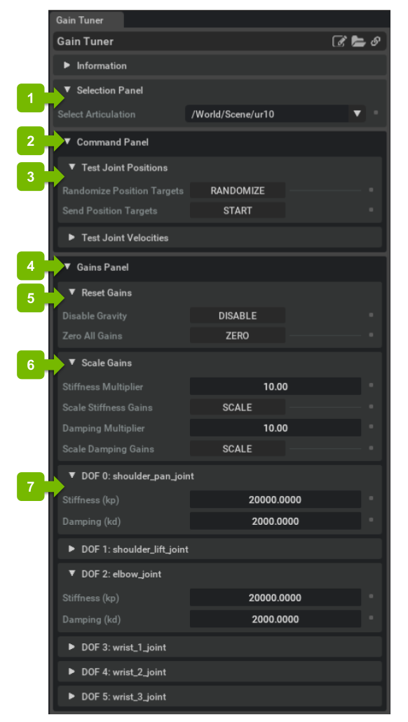
The user will find that many sets of gains are sufficient to achieve near-perfect position and velocity tracking characteristics. One easy answer is to simply click the “SET STIFF GAINS” button. This will set the stiffness for each joint to 1e15 and the damping for each joint to 1e5. In the world of factory robot arms, setting stiff gains on the robot arm is a perfectly reasonable approximation of the real thing, as it will mean that the joints go exactly where they are told, and in the case of collision with the environment, they have no compliance. But in the case of robot manipulators, compliance in certain joints is likely to be important. In these cases, it becomes necessary to hand-tune gains to match the specific use-case.
In the Gain Tuner under Tune Gains -> Hand Tune Gains, each joint can be tuned individually. The gains for each joint are expressed in a log scale. I.e. a value of 4.3 indicates that a gain is 10^4.3 or 2e4. These may be modified individually or all together with the “Stiffness Multiplier” and “Damping Multiplier” fields at the top of the panel.
Gains Test Settings#
Gains Test Settings allow the user to modify various parameters of the gains tests to enable the user to explore the behavior associated with their robot gains. Some of the parameters are over-specified, meaning that modifying one parameter may change another automatically.
Test Duration#
The duration of each gains test (in seconds). It may be necessary to lengthen this parameter if an asset is slow-moving due to a low maximum velocity in order to see a full step function or sinusoid period.
Joint Range Maximum#
Maximum range any joint will be moved in either gains test. This parameter defaults to 2*pi. Some assets have joint limits that allow many full rotations, which would greatly increase the duration of one sinusoid period. It may be necessary to modify this parameter in order to observe the behavior of joints near their position limits.
Joint Range Used#
After the joint ranges tested are limited by Joint Range Maximum, they are further limited by this scalar factor. This parameter’s default value of .9 means that no joint will come within 10% of its position limits. It is necessary to modify this parameter in order to observe the behavior of joints near their position limits.
Initial Position Impulse#
Impulse in the initial robot joint positions. Setting this parameter to a non-zero value c will cause each joint in each gains test to start the test with a position offset of c. This demonstrates the behavior of a joint when the commanded position is discontinuous from the current position. Ideally this will resolve itself quickly for reasonably small impulses.
Initial Position Impulse of 1.0#
Initial Velocity Impulse#
Impulse in the initial robot joint velocities. Setting this parameter to a non-zero value c will cause each joint in each gains test to start the test with a velocity offset of c. This demonstrates the behavior of a joint when the commanded velocity is discontinuous from the current velocity. Ideally this will resolve itself quickly for reasonably small impulses.
Initial Velocity Impulse of 1.0#
Max Velocity#
Maximum velocity reached at the peack of the velocity sinusoid in the Sinusoidal Gains Test. This is over-constrained by joint range and period. I.e. decreasing the maximum velocity reached will increase the period of the sinusoids and vice versa. The Max Velocity parameter is bounded above by the Articulation’s maximum velocity and maximum acceleration (an asset with a very low maximum acceleration cannot reach a high maximum velocity by the middle of the joint range).
Period#
Period of the commanded sinusoid. This is over-constrained by joint range and max velocity. I.e. decreasing period will necessarily increase the maximum velocity. As such, period is bounded below by the upper bound of max velocity. It may be of interest to vary period parameters in order to observe Coreolis effects between different joints.
Include Joint In Gains Test#
Option to keep a joint still for the duration of each gains test. If this parameter is unchecked, the corresponding joint will be sent a fixed position command and a zero-velocity command for the duration of each gains test. This can be helpful to ensure that joints can stay tightly converged even when the rest of the asset is moving around. Combining this option with an initial position impulse can also serve to demonstrate convergence behavior.
Further Learning#
The Tuning Joint Drive Gains tutorial goes into more specific detail about the physical mechanics relating joint gains to derived motions.