RTX Lidar Sensors#
Isaac Sim RTX or Raytraced Lidar supports both Solid State and Rotating Lidar configuration via a JSON config file. Each RTX Sensor must be attached to its own viewport to simulate properly.
Warning
Docking windows in the isaac-sim UI when an RTX Lidars simulation is running will likely lead to a crash. Please pause the simulation before re-docking the window.
Warning
ROS 2 Foxy is no longer tested or supported. This may result in potential issues when ROS 2 Foxy is used in conjunction with Isaac Sim 4.2 or later.
Learning Objectives#
In this example, we will
Briefly introduce how to use RTX Lidar sensors.
Create a RTX Lidar sensor.
Publish sensor data to ROS2 as LaserScan and PointCloud2 messages.
Use the menu shortcut to create RTX Lidar sensor publishers.
Put it all together and visualize multiple sensors in Rviz2.
Getting Started#
Important
Make sure to source your ROS 2 installation from the terminal before running Isaac Sim. If sourcing ROS 2 is a part of your bashrc then Isaac Sim can be run directly.
Prerequisites
Completed the ROS2 ROS2 Cameras tutorial.
FASTRTPS_DEFAULT_PROFILES_FILEenvironmental variable is set prior to launching sim, and ROS2 bridge is enabled.OPTIONAL: Explore the inner workings of RTX Lidar sensors by learning How They work, the RTX Lidar Nodes that use them, and how to get RTX Lidar Synthetic Data.
Completed the URDF Import: Turtlebot tutorial so that Turtlebot is loaded and moving around.
Note
In Windows 10 or 11, depending on your machine’s configuration, RViz2 may not open properly.
Adding a RTX Lidar ROS2 Bridge#
First we need to add a Lidar sensor to the robot. Go to Create -> Isaac -> Sensors -> RTX Lidar -> Rotating.
To place the synthetic Lidar sensor at the same place as the robot’s Lidar unit, drag the Lidar prim under /World/turtlebot3_burger/base_scan. Zero out any displacement in the Transform fields inside the Property tab. The Lidar prim should now be overlapping with the scanning unit of the robot.
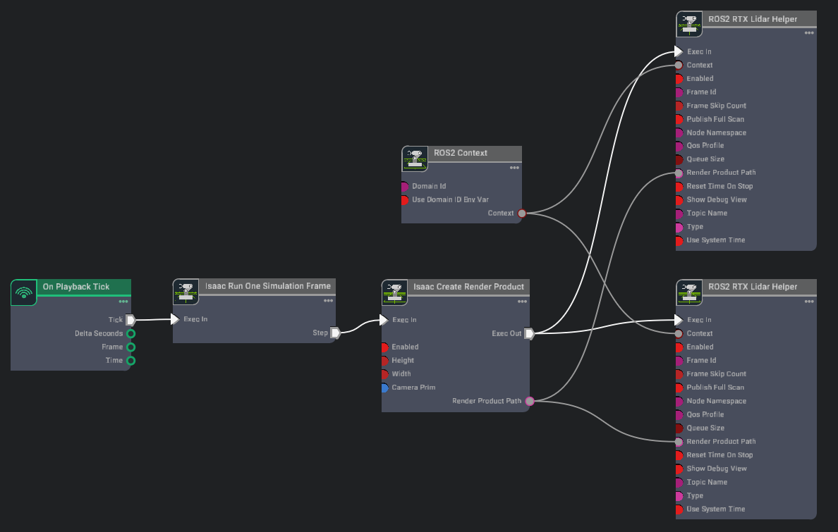
Next we connect the ROS2 bridge with the sensor output via Omnigraph Nodes. Open visual scripting editor by going to Window -> Visual Scripting -> Action Graph. Add the following nodes to this graph:
On Playback Tick: This is the node responsible for triggering all the other nodes once Play is pressed.
ROS2 Context Node: ROS2 uses DDS for its middleware communication. DDS uses Domain ID to allow for different logical networks operate independently even though they share a physical network. ROS 2 nodes on the same domain can freely discover and send messages to each other, while ROS 2 nodes on different domains cannot. ROS2 context node creates a context with a given Domain ID. It is set to 0 by default. If Use Domain ID Env Var is checked, it will import the
ROS_DOMAIN_IDfrom the environment in which you launched the current instance of Isaac Sim.Isaac Run One Simulation Frame: This is the node to running the create render product pipeline once at the start to improve performance.
Isaac Create Render Product: In the input camera target prim select the RTX Lidar created in step 2.
ROS2 RTX Lidar Helper: This node will handle publishing of the laser scan message from the RTX Lidar. The input render product is obtained from the output of Isaac Create Render Product in step b.
If you wish to also publish point cloud data, add another ROS2 RTX Lidar Helper node, and under input type select point_cloud and change the topic name to
point_cloud. This node will handle publishing the point cloud from the RTX Lidar. The input render product is obtained from the output of Isaac Create Render Product in step b.
Note
When type is set to laser_scan in the ROS2 RTX Lidar Helper node, the LaserScan message will only be published when the RTX Lidar generates a full scan. For a rotary Lidar this is a full 360-degree rotation, while for a solid state Lidar this is the full azimuth of the Lidar, as configured in its profile. Depending on Lidar rotation rate and time step size, it may take multiple frames to complete the full rotary scan; eg. for render step size 1/60s, a rotary Lidar with rotation rate 10Hz would take 6 frames to complete a full scan, meaning the LaserScan message would be published once every 6 frames. Solid state Lidars complete the full scan in a single frame, so the corresponding LaserScan message would be published every frame.
PointCloud messages are published either every frame or once the full scan has been accumulated, based on the value of the Publish Full Scan setting in the ROS2 RTX Lidar Helper node.
Once the graph has been set correctly, hit Play to begin simulation. The RTX Lidar should be sending the LaserScan and PointCloud2 messages and can be visualized in RViZ.
For RViZ visualization:
Run RViZ2 (
rviz2) in a sourced terminal.The fixed frame name in Isaac Sim for the RTX Lidar is set to sim_lidar, update the Rviz side accordingly.
Add LaserScan visualization and set topic to /scan
Add PointCloud2 visualization and set topic to /point_cloud
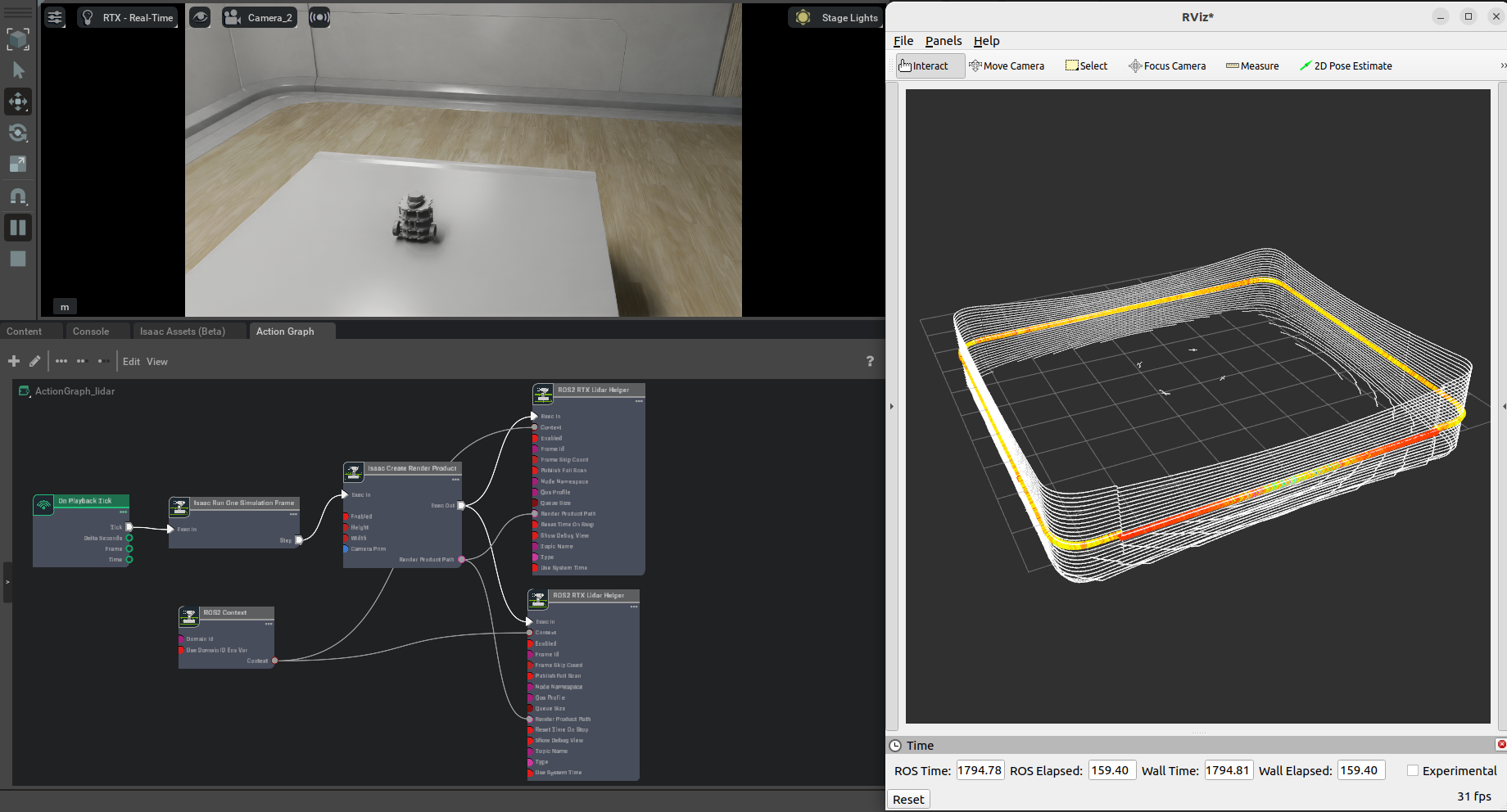
Graph Shortcut#
We provide a menu shortcut to build multiple Lidar sensor graphs with just a few clicks. Go to Isaac Utils > Common Omnigraphs > ROS2 RTX Lidar. (If you don’t see any ROS2 graphs listed, you need to first enable the ROS2 bridge). A popup will appear asking for the parameters needed to populate the graphs. You must provide the Graph Path, the Lidar Prim, frameId, any Node Namespaces if you have one, and check the boxes for the data you wish to publish. If you wish to add the graphs to an existing graph, check the “Add to an existing graph?” box. This will append the nodes to the existing graph, and use the existing tick node, context node, and simulation time node if they exist.
Running The Example#
In a new terminal with your ROS2 environment sourced, run the following command to start rviz and show the Lidar point cloud. Replace
ros2_wswithfoxy_wsorhumble_wsas appropriate.rviz2 -d <ros2_ws>/src/isaac_tutorials/rviz2/rtx_lidar.rviz
Finally, run the sample script
./python.sh standalone_examples/api/omni.isaac.ros2_bridge/rtx_lidar.py
After the scene finishes loading, verify that you see the point cloud for the rotating Lidar sensor being simulated.
RTX Lidar Script sample#
While most of the sample code is fairly generic, there are a few specific pieces needed to create and simulate the sensor.
We first need to create the RTX Lidar Sensor
_, sensor = omni.kit.commands.execute(
    "IsaacSensorCreateRtxLidar",
    path="/sensor",
    parent=None,
    config="Example_Rotary",
    translation=(0, 0, 1.0),
    orientation=Gf.Quatd(1.0, 0.0, 0.0, 0.0),
)
Here Example_Rotary defines the configuration for the Lidar sensor. Two generic configuration files (in addition to manufacturer/model-specific configurations) provided in extsbuild/omni.sensors.nv.common/data/lidar/: Example_Rotary.json and Example_Solid_State.json. To switch the Lidar to the example solid state configuration you can replace config=”Example_Rotary”, with config=”Example_Solid_State”.
Next, we need create a render product and attach this sensor to it
hydra_texture = rep.create.render_product(sensor.GetPath(), [1, 1], name="Isaac")
We can then create the post process pipeline that takes the rendered RTX Lidar data and publishes it to ROS:
writer = rep.writers.get("RtxLidar" + "ROS2PublishPointCloud")
writer.initialize(topicName="point_cloud", frameId="sim_lidar")
writer.attach([hydra_texture])
Note
You can specify an optional attributes={…} dictionary when calling activate_node_template to set node specific parameters. See the API Documentation for complete usage information.
Multiple Sensors in RViz2#
To display multiple sensors in RViz2, there are a few things that are important to make sure all the messages are synced up and timestamped correctly.
Simulation Timestamp
Use Isaac Read Simulation Time as the node that feeds the timestamp into all of the publishing nodes’ timestamps.
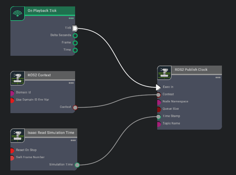
ROS clock
To publish the simulation time to the ROS clock topic, you can setup the graph as shown in the Running ROS 2 Clock Publisher tutorial:
frameId and topicName
To visualize all the sensors as well as the tf tree all at once inside RViz, the frameId and topicNames must follow a certain convention in order for Rviz to recognize them all at once. The table below roughly describes these conventions. To see the multi-sensor example below, consult the USD asset
Isaac/Samples/ROS2/Scenario/turtlebot_tutorial.usd.Source
frameId
nodeNamespace
topicName
type
Camera RGB
(device_name):(data_type)
(device_name)/(data_type)
image_raw
rgb
Camera Depth
(device_name):(data_type)
(device_name)/(data_type)
image_rect_raw
depth
Lidar
world
scan
laser_scan
TF
tf
tf
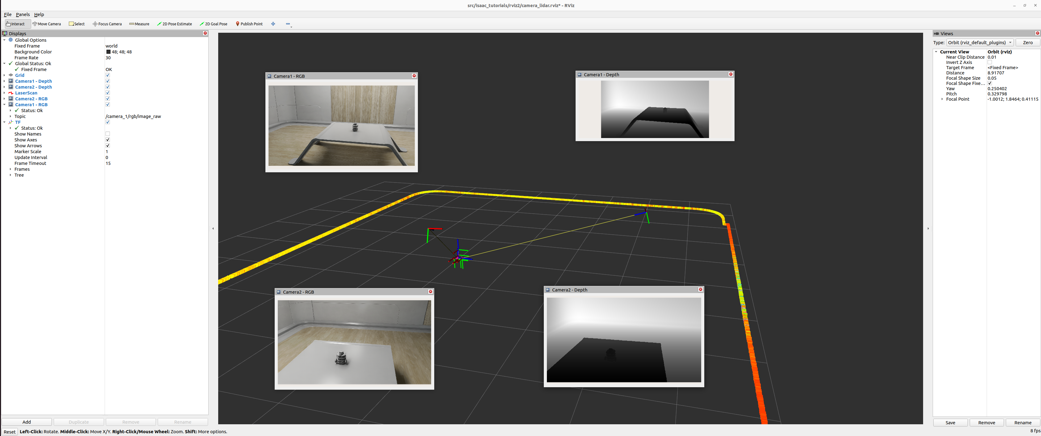
To see the rviz image below, make sure the simulation is playing. In a ROS2-sourced terminal, open with the configuration provided using the command:
ros2 run rviz2 rviz2 -d <ros2_ws>/src/isaac_tutorials/rviz2/camera_lidar.rviz. Once the Rviz window finishes loading, you can enable and disable the sensor streams inside the “Display” Panel on the left hand side.
Important
Ensure that the use_sim_time ROS2 param is set to true after running the RViz2 node.
This ensures that the RViz2 node is synchronized with the simulation data especially when RViz2 interpolates position of Lidar data points.
Set the parameter using the following command in a new ROS2-sourced terminal:
ros2 param set /rviz use_sim_time true
Summary#
This tutorial covered creating and using the RTX Lidar Sensor with ROS2:
Adding a RTX Lidar sensor
Adding a RTX Lidar and PointCloud ROS2 nodes.
Displaying multiple sensors in RViz2.
Next Steps#
Continue on to the next tutorial in our ROS2 Tutorials series, ROS2 Transform Trees and Odometry, to learn how to add global and relative transforms to a TF tree.
Further Learning#
Explore the inner workings of RTX Lidar sensors by learning How They work, the RTX Lidar Nodes that use them, and how to get RTX Lidar Synthetic Data.