RTX – Interactive (Path Tracing) mode#
Omniverse RTX Renderer provides the RTX – Interactive (Path Tracing) mode, a cutting-edge rendering mode designed to accurately simulate the behavior of light in order to predict how illumination interacts with materials and environments in real-world scenarios.
RTX – Interactive (Path Tracing) mode is complemented by the RTX - Real-Time 2.0 mode, which can achieve similar results with some fidelity trade-offs, at real-time performance. See the RTX - Real-Time 2.0 mode documentation for more details.
Which render mode is enabled at startup can be modified.
In the application’s Preferences UI’s under Edit -> Preferences -> Rendering -> RTX Renderers. By default none are specified, which results in the RTX Renderer determining its own default modes to enable. If any are enabled through this UI, upon restarting the application, only those will now be enabled.
With commands at startup:
--/persistent/rtx/modes/rt2/enabled=truefor the RTX - Real-Time 2.0 mode,--/persistent/rtx/modes/pt/enabled=truefor the RTX – Interactive (Path Tracing) mode, and--/persistent/rtx/modes/rt/enabled=truefor the RTX Real-Time (Legacy) mode.
Path Tracing#
Display Name |
Setting Name |
Type and Default Value |
Description |
|---|---|---|---|
Samples per Pixel per Frame (1 to 32) |
|
|
Total number of samples for each rendered pixel, per frame. |
Total Samples per Pixel (0 = inf) |
|
|
Maximum number of samples to accumulate per pixel. When this sample count is reached the rendering stops until a scene or setting change is detected, restarting the rendering process. Set to 0 to remove this limit. |
Adaptive Sampling |
|
|
When enabled, noise values are computed for each pixel, and upon threshold level reached, the pixel is no longer sampled. |
|
|
|
The noise value threshold after which the pixel would no longer be sampled. |
Max Bounces |
|
|
Maximum number of ray bounces for any ray type. Higher values give more accurate results, but worse performance. |
Max Specular and Transmission Bounces |
|
|
Maximum number of ray bounces for specular and transmission. |
Max SSS Volume Scattering Bounces |
|
|
Maximum number of ray bounces for SSS. |
Max Fog Scattering Bounces |
|
|
Maximum number of bounces for volume scattering within a fog volume. |
Fractional Cutout Opacity |
|
|
If enabled, fractional cutout opacity values are treated as a measure of surface ‘presence’, resulting in a translucency effect similar to alpha-blending. Path-traced mode uses stochastic sampling based on these values to determine whether a surface hit is valid or should be skipped. |
Reset Accumulation on Time Change |
|
|
If enabled, the Path-Tracer accumulation is restarted every time the MDL animation time changes. Settings this to false is useful to prevent accumulation reset at every frame when the ‘animation time’ is changing every frames using wall clock time (which can be the case when an animation is not being played, and wall clock time is used instead of animation time). |
Note
While using a higher number of bounces increases accuracy of the final image, it may result in diminishing returns in terms of image quality relative to performance.
About Adaptive Sampling#

The RTX – Interactive (Path Tracing) mode supports Adaptive Sampling. With Adaptive Sampling, samples are non-uniformly distributed where most beneficial for further convergence, which can result in less noise for the same number of samples and also provides a more consistent noise level across multiple frames.
Adaptive Sampling can be enabled in the RTX – Interactive (Path Tracing)’s render settings, and its Target Error value can be adjusted there as well, which when reached will stop accumulating more samples.
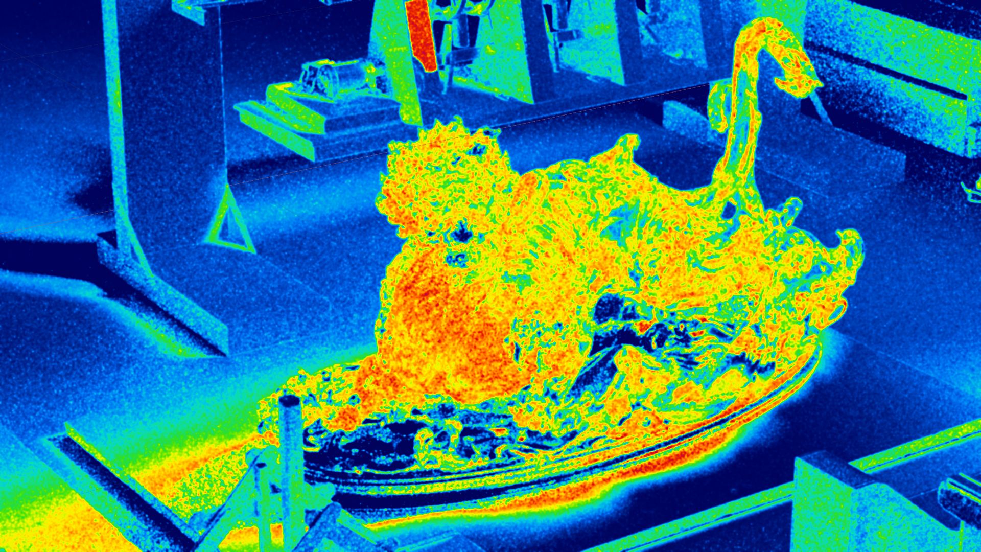
An Adaptive Sampling Error debug view can be selected in the Debug View render settings, which allows visualizing the normalized standard deviation of the Monte Carlo estimator of the pixels: warm colors represent high variance, which indicate that additional samples would lead to improved convergence for those pixels.
Note that currently Movie Capture does not support ending the rendering of a frame earlier when the Target Error threshold has been reached, but it will be supported in a future release.
Sampling & Caching#
Display Name |
Setting Name |
Type and Default Value |
Description |
|---|---|---|---|
Caching |
|
|
Enables caching path tracing results for improved performance at the cost of some accuracy. |
Many-Light Sampling |
|
|
Enables a technique that improves the sampling quality (and therefore rendering convergence) in scenes with many light primitives. |
Mesh-Light Sampling |
|
|
Enables direct illumination sampling of geometry with emissive materials. |
Anti-Aliasing#
Display Name |
Setting Name |
Type and Default Value |
Description |
|---|---|---|---|
Anti-Aliasing Sample Pattern |
|
|
Sampling pattern used for Anti-Aliasing. Select between Box (0), Triangle (1), Gaussian (2) and Uniform (3). |
Anti-Aliasing Radius |
|
|
The sampling footprint radius, in pixels, when generating samples with the selected antialiasing sample pattern. |
Firefly Filtering#
Display Name |
Setting Name |
Type and Default Value |
Description |
|---|---|---|---|
Firefly Filtering |
|
|
Enables image filtering to reduce the presence of excessively bright “firefly” pixel artifacts. |
Max Ray Intensity Glossy |
|
|
Clamps the maximum ray intensity for glossy bounces. Can help prevent fireflies, but may result in energy loss. |
Max Ray Intensity Diffuse |
|
|
Clamps the maximum ray intensity for diffuse bounces. Can help prevent fireflies, but may result in energy loss. |
Denoising#
Display Name |
Setting Name |
Type and Default Value |
Description |
|---|---|---|---|
Denoising |
|
|
Enable to apply the OptiX Denoiser to the radiance image generated by the renderer. The OptiX denoiser results in an order of magnitude reduction in rendering times for a target image quality. |
Optix Denoiser Temporal Mode |
|
|
Can denoise multi-frame animation sequences without low-frequency denoiser artifacts commonly seen in animated frames denoised separately. |
Optix Denoiser Blend Factor |
|
|
A blend factor indicating how much to blend the denoised image with the original non-denoised image. 0 shows only the denoised image, 1.0 shows the image with no denoising applied. |
Denoise AOVs |
|
|
If enabled, the OptiX Denoiser will also denoise the AOVs. |
Non-uniform Volumes#
This feature enables path-traced volume rendering of both VDB files (internally converted to NanoVDB, a faster and more compact GPU-friendly volume representation) and procedural MDL based volumes. VDB files can either contain a SDF (signed distance field/level set) or density volume. Currently, the VDB volume material can only be applied to a cube mesh, while procedural volume materials can be applied to any kind of mesh (cube, sphere, torus, etc.). Volumes can also overlap with other volumes. The maximum number of overlaps between the volumes is currently limited to four.
Display Name |
Setting Name |
Type and Default Value |
Description |
|---|---|---|---|
Non-uniform Volumes |
|
|
The number of bounces is controlled by Max Heterogeneous Volume Scattering Bounces (under the Path Tracing section in Path-Traced Mode Settings). When set to 1: perform single scattering; fast, suitable for lowly scattering volumes like fog. Higher values result in multi-scattering; slower, suitable for highly scattering volumes like clouds. |
Transmittance Method |
|
|
Choose between Biased Ray Marching (0) or Ratio Tracking (1). Biased ray marching is the ideal option in all cases. |
Max Collision Count |
|
|
Maximum delta tracking iterations. Increase to more than 32 for highly scattering volumes like clouds. Important: if set too low, parts of the volume will disappear. |
Max Light Collision Count |
|
|
Maximum ratio tracking iterations. Increase to more than 32 for highly scattering volumes like clouds. Important: if set too low, parts of the volume will disappear. |
Max Non-Uniform Volume Scattering Bounces |
|
|
Maximum number of ray bounces for non-uniform volumes. |
Global Volumetric Effects#
Display Name |
Setting Name |
Type and Default Value |
Description |
|---|---|---|---|
Rayleigh Atmosphere |
|
|
Enables an additional medium of Rayleigh-scattering particles to simulate a physically based sky. |
|
|
|
Scales the size of the Rayleigh sky. |
|
|
|
If a domelight is rendered for the sky color, the Rayleight Atmosphere is applied to the foreground while the background sky color is left unaffected. |
AOV#

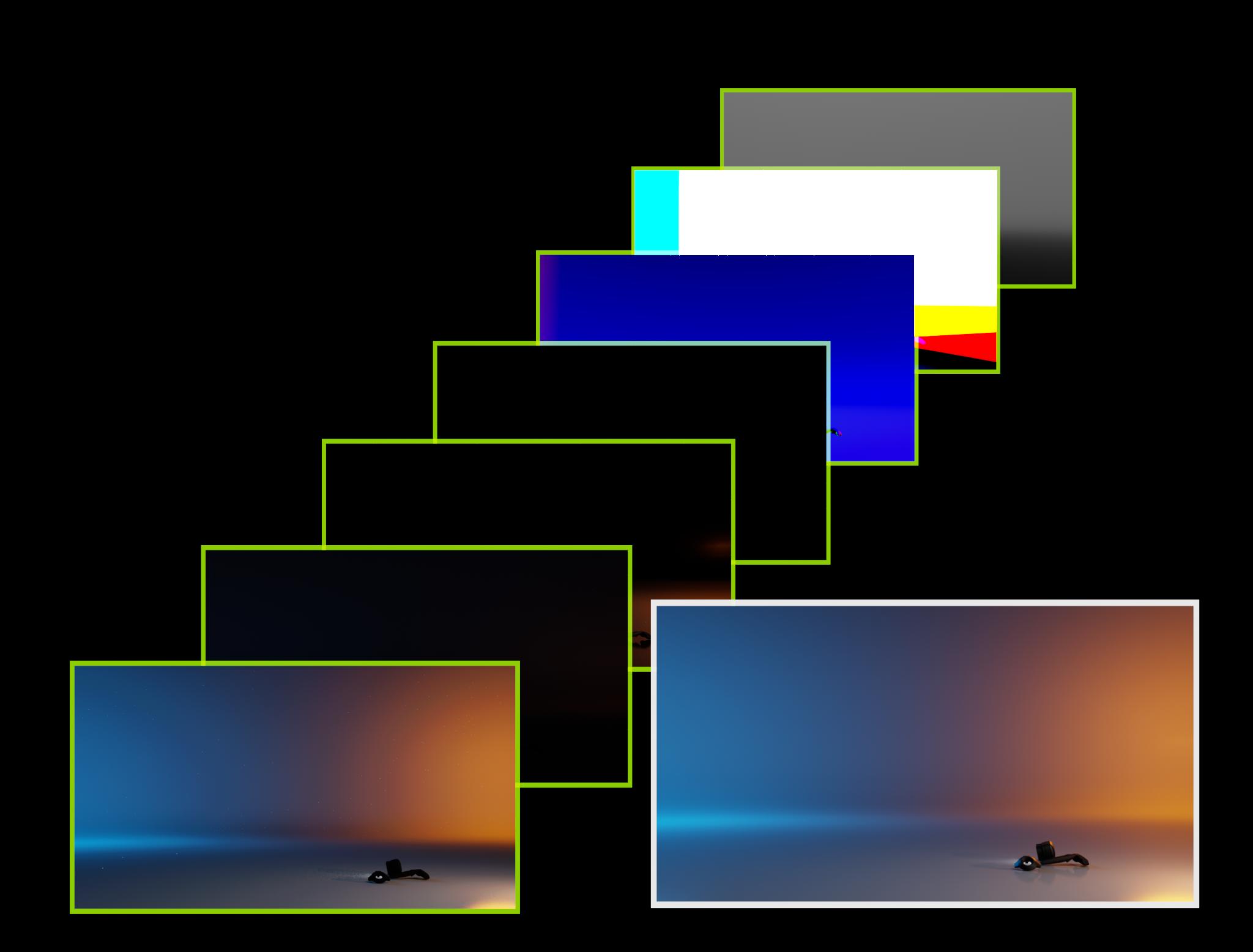
AOVs (Arbitrary Output Variables) are data known to the renderer and used to compute illumination. Typically, AOVs contain decomposed lighting information such as:
Direction and indirect illumination
Reflections and refractions
Objects with self illumination
But they can also contain geometric and scene information, such as:
Surface position in world-space
Orientation of normals
View-relative depth
As the final image is computed, the intermediate information used during rendering can be optionally written to disk, providing opportunities to modify the final image during compositing and additional insights through 2D analysis. The auxiliary images, called “passes” in Omniverse and “Render Products” in USD, are just named outputs. The AOV data used by the renderer is referred to as a “Render Variable” and defines what is written for each pass.
If the OptiX Denoiser is enabled (true by default) the AOVs will be denoised. An option to control this is available in Denoising settings.
Debug View contains a list of the AOV passes which can be displayed if enabled for previewing.
AOV Common Settings#
Display Name |
Setting Name |
Type and Default Value |
Description |
|---|---|---|---|
Minimum Z-Depth |
|
|
The minimum z-depth for AOVs. The depth range can be shorted when necessary to increases the precision. |
Maximum Z-Depth |
|
|
The maximum z-depth for AOVs. The depth range can be shorted when necessary to increases the precision. |
32-Bit Depth AOV |
|
|
Uses a 32-bit format for the depth AOV. |
AOV Passes#
Display Name |
Setting Name |
Type and Default Value |
Description |
|---|---|---|---|
Background |
|
|
Shading of the background, such as the background resulting from rendering a Dome Light. |
Diffuse Filter |
|
|
The raw color of the diffuse texture. |
Direct Illumination |
|
|
Shading from direct paths to light sources. |
Global Illumination |
|
|
Diffuse shading from indirect paths to light sources. |
Illuminance |
|
|
The amount of light falling onto (illuminating) and spreading over a given surface area. |
Luminance |
|
|
The intensity of light emitted from a surface per unit area in a given direction. |
Motion Vectors |
|
|
Motion vectors. |
Reflections |
|
|
Shading from indirect reflection paths to light sources. |
Reflection Filter |
|
|
The raw color of the reflection, before being multiplied for its final intensity. |
Refractions |
|
|
Shading from refraction paths to light sources. |
Refraction Filter |
|
|
The raw color of the refraction, before being multiplied for its final intensity. |
Self-Illumination |
|
|
Shading of the surface’s own emission value. |
Subsurface Filter |
|
|
The raw color of the subsurface scattering texture. |
View Normal |
|
|
The surface’s normal in view-space. |
Volumes |
|
|
Shading from VDB volumes. |
World Normal |
|
|
The surface’s normal in world-space. |
World Position |
|
|
The surface’s position in world-space. |
Z-Depth |
|
|
The surface’s depth relative to the view position. |
Multi Matte#

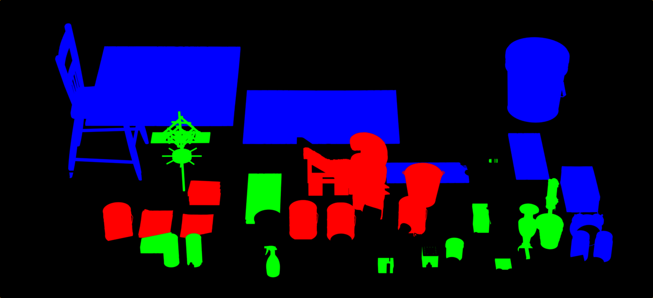
Multi Matte extends AOV support by enabling rendering masked mesh geometry and materials to AOVs.
The Multi Matte channel count defines the total number of channels available, and each is assigned to a Multi Matte AOV’s color channel (red, green, or blue). Each channel has an index, and Mesh geometry or materials with a matching Multi Matte ID index will be rendered to the first Multi Matte AOV channel found with a matching index.
If a geometry has a Multi Matte ID set, and has a material assigned with a Multi Matte ID set, then the ID on the geometry takes precedence.
In order to set a Multi Matte ID on a material, add the attribute uniform int multimatte_id to the Material prim.
Debug View contains a list of all Multi Matte AOV passes which can be previewed.
Warning
Note that when capturing RenderProducts other than the Viewport RenderProduct, the attributes int omni:rtx:pt:multimatte:channel<N> and int omni:rtx:pt:multimatte:channelCount must be set on each RenderProduct to be captured, otherwise no Multi Matte outputs will be generated.
Display Name |
Setting Name |
Type and Default Value |
Description |
|---|---|---|---|
Channel Count |
|
|
Multimatte allows rendering AOVs of meshes which have a Multimatte ID index matching a Multimatte AOV’s channel index. Channel Count determines how many channels can be used, which are distributed among the Multimatte AOVs’ color channels. You can preview a Multimatte AOV by selecting one in the Debug View render settings. |
Multimatte AOV |
|||
|
|
|
The Multimatte ID index to match for the red channel of this Multimatte AOV. |
|
|
|
The Multimatte ID index to match for the green channel of this Multimatte AOV. |
|
|
|
The Multimatte ID index to match for the blue channel of this Multimatte AOV. |
Multi-GPU#
Multi-GPU mode distributes the image across the GPUs while automatically balancing the workload. Automatic Load Balancing can improve performance, particularly at high resolution and with mixed GPU models of varying capacity.
The primary GPU performs various tasks, such as: rendering pixels, sample aggregation, denoising, post processing, UI rendering. The default GPU 0 Weight value is usually ideal.
Display Name |
Setting Name |
Type and Default Value |
Description |
|---|---|---|---|
Multi-GPU |
|
|
Enables using multiple GPUs (when available). This splits the rendering of the image into a large tile per GPU with a small overlap region between them. |
Automatic Load Balancing |
|
|
Automatically balances the amount of total path tracing work to be performed by each GPU in a multi-GPU configuration. |
GPU (index) Weight |
|
|
The amount of total Path Tracing work (between 0 and 1) to be performed by the first GPU in a Multi-GPU configuration. A value of 1 means the first GPU will perform the same amount of work assigned to any other GPU. Ignored if Automatic Load Balancing is enabled. |
Compress Radiance |
|
|
Enables lossy compression of per-pixel output radiance values. |
Compress Albedo |
|
|
Enables lossy compression of per-pixel output albedo values (needed by OptiX denoiser). |
Compress Normals |
|
|
Enables lossy compression of per-pixel output normal values (needed by OptiX denoiser). |
Multi-Threading |
|
|
Enabling multi-threading improves UI responsiveness. |
Note
In simple scenes, Automatic Load Balancing may not make a significant difference, and may take more time in scenes with low frame rates.
Limitations#
Multi-GPU rendering lowers the cost of rendering more pixels and is ideal for high-resolution rendering, particularly for the RTX Interactive (Path Tracing) mode. It will not improve performance for animations, physics, etc.
For efficiency’s sake, in some contexts rendering will switch to single-GPU automatically until conditions warrant multi-GPU rendering, for example when rendering at low resolution.
Multi-GPU rendering is enabled by default if the system has multiple NVIDIA RTX-enabled GPUs of the same model.
Per-GPU memory usage is limited to 48GB.
Multi-GPU is disabled for mixed-GPU configurations. This can be overridden with a setting. Note that the GPU with the lowest memory capacity will limit the amount of memory the other GPUs can leverage.
GPUs which don’t support ray tracing are skipped automatically.
Note that LDA (SLI) configurations are only supported on DX12, not on Vulkan.
Note
A GPU information table is logged to the omniverse .log file under [gpu.foundation] listing which GPUs are set as Active. Each GPU has a device index assigned and this index can be used with the multi-GPU settings below.
Setting Name |
Type and Default Value |
Description |
|---|---|---|
|
|
Specifies if multi-GPU is enabled, but multi-GPU is disabled if the NVIDIA RTX-enabled GPUs are not of the same model; setting this to true will enable multi-GPU anyway. |
|
|
Enables only a subset of GPUs, specified by a comma-separated list of device indices. |
|
|
Specifies the maximum number of NVIDIA RTX-enabled GPUs. GPUs which don’t support ray tracing are skipped automatically. |