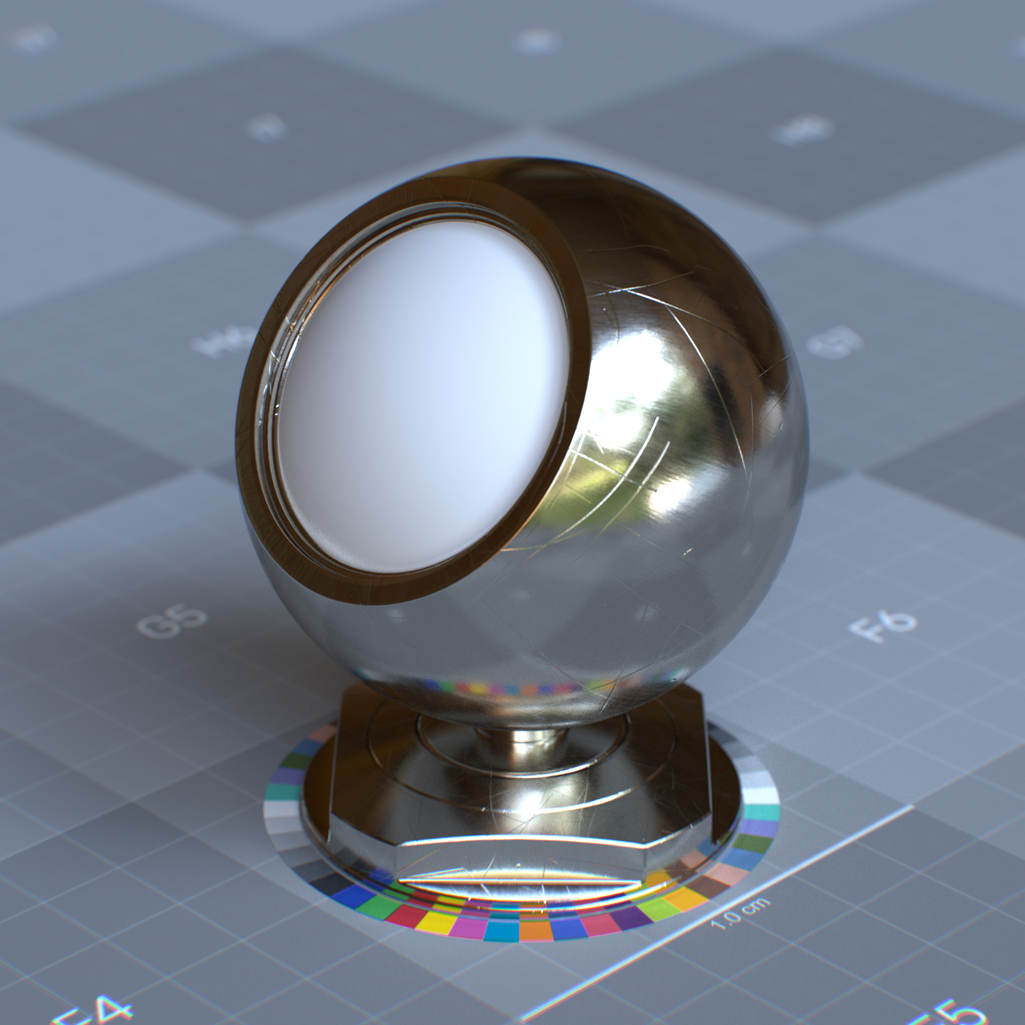
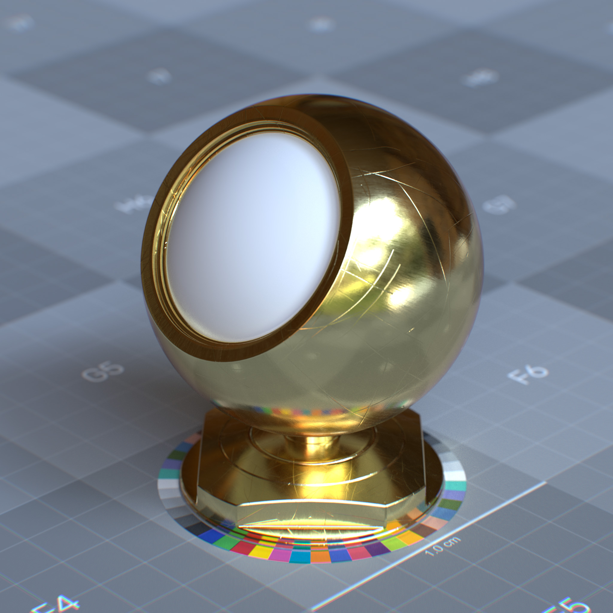
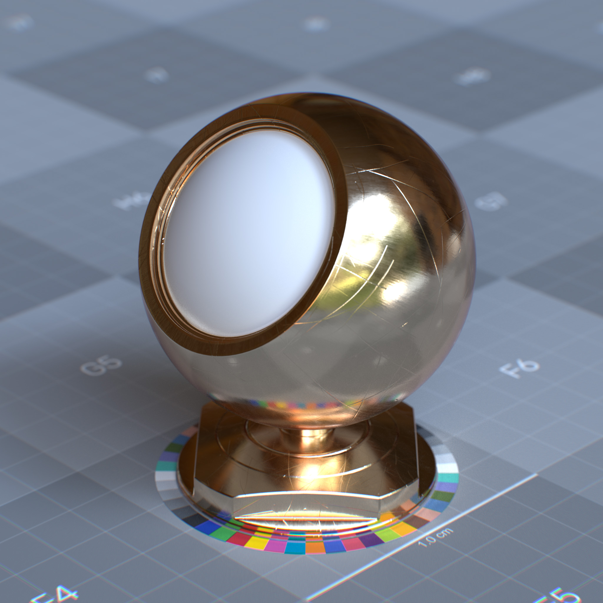
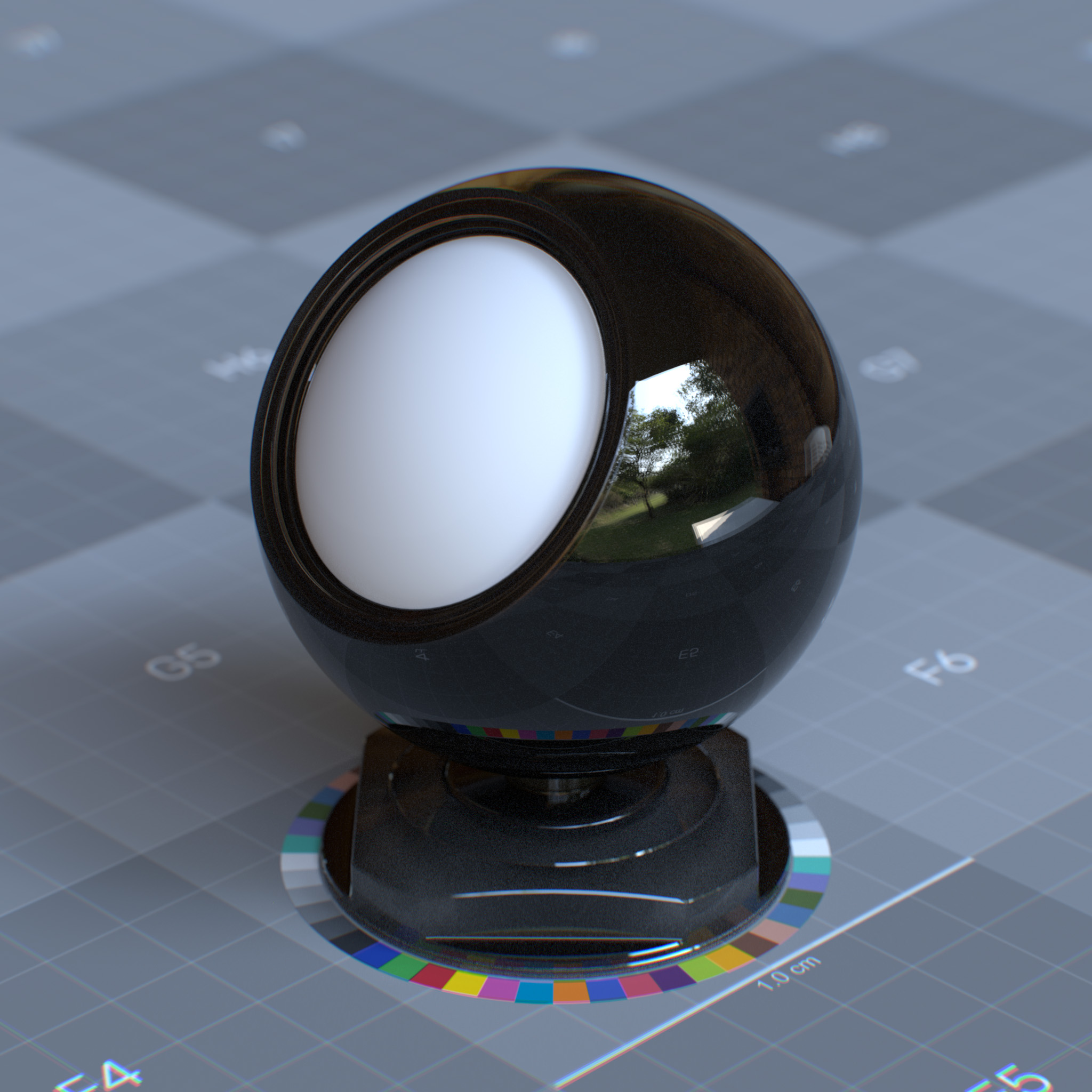
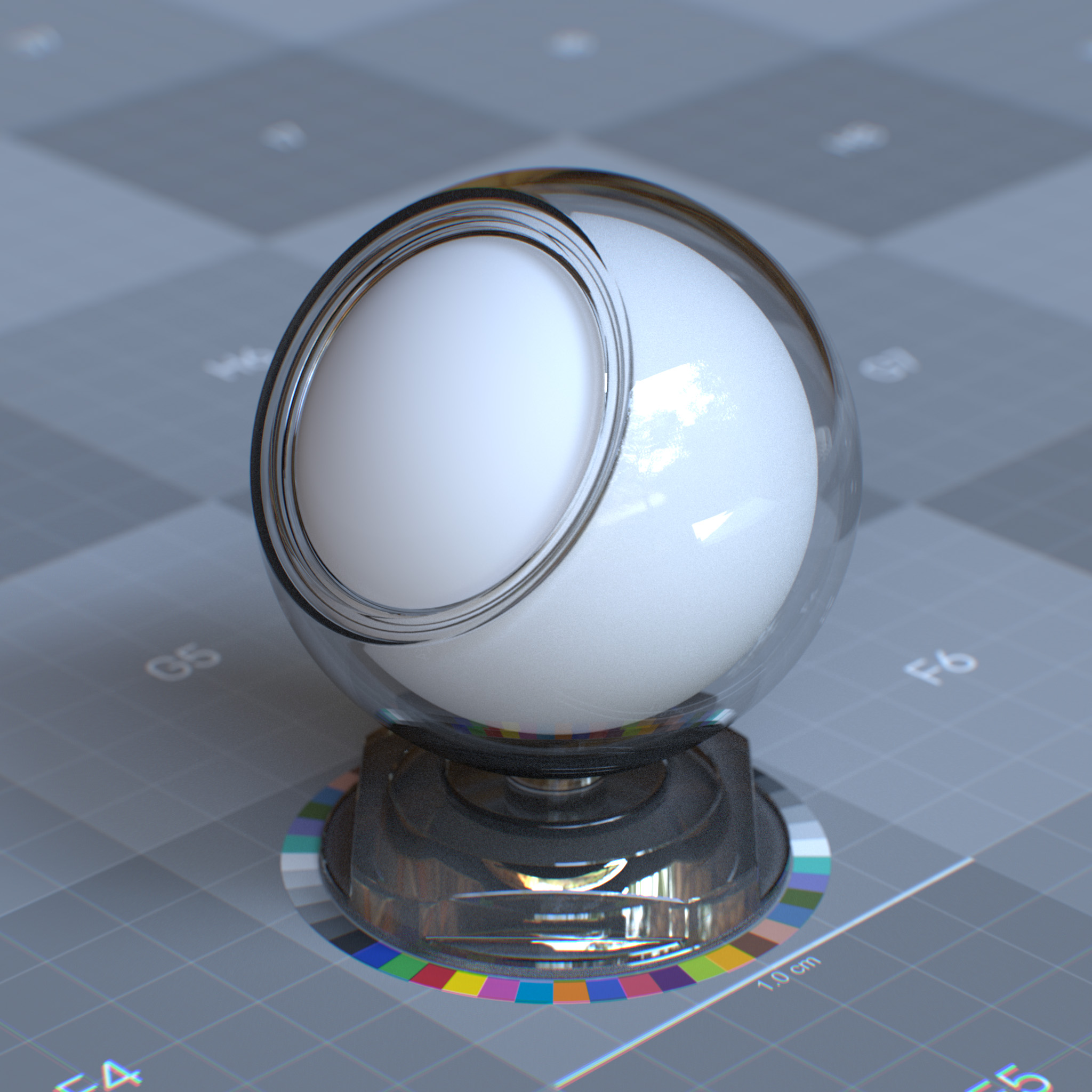
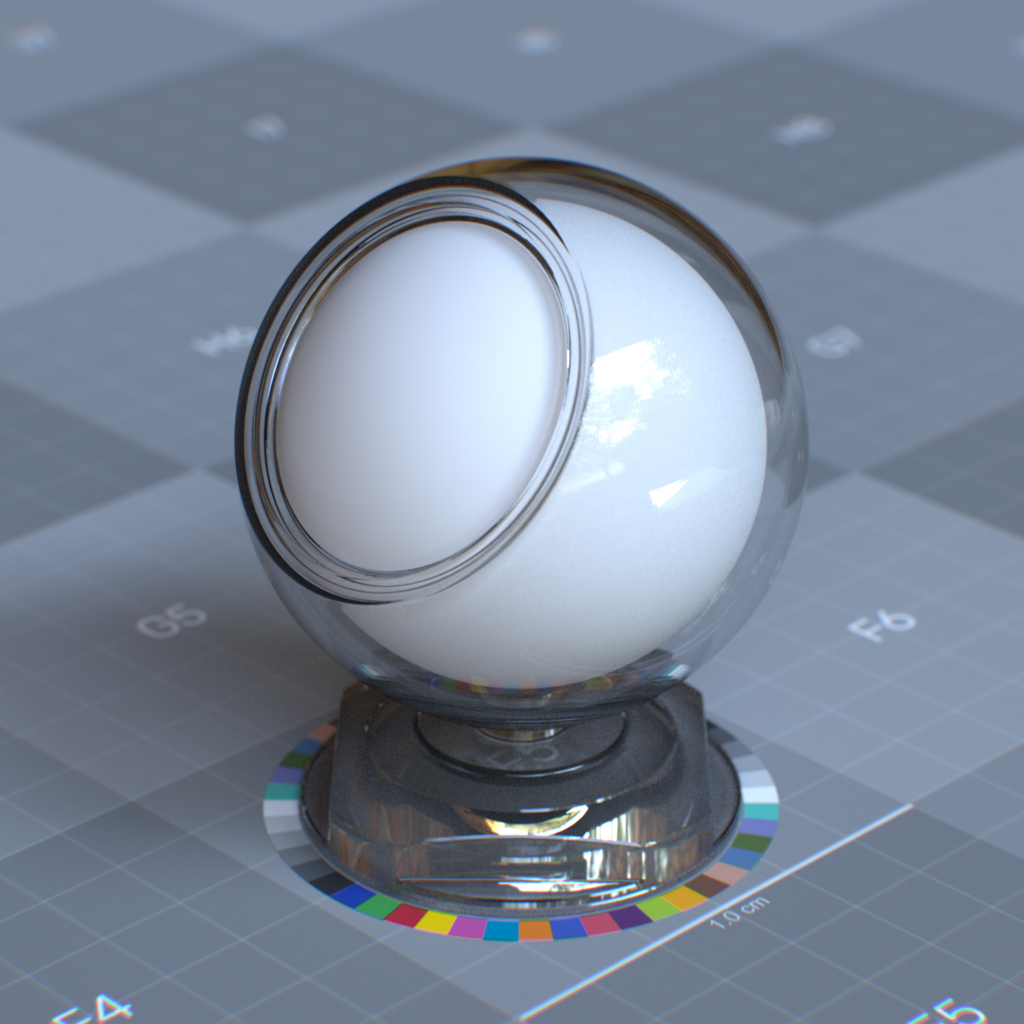
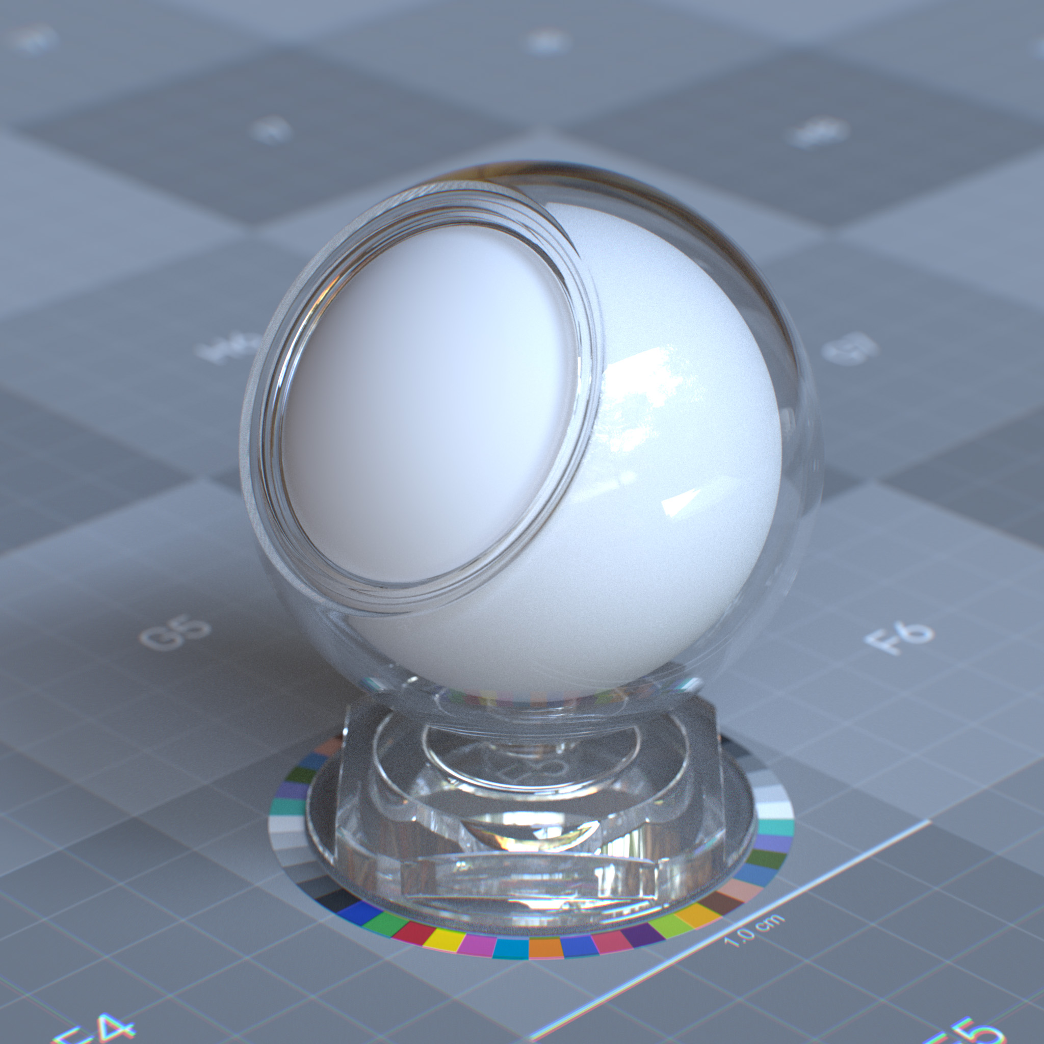
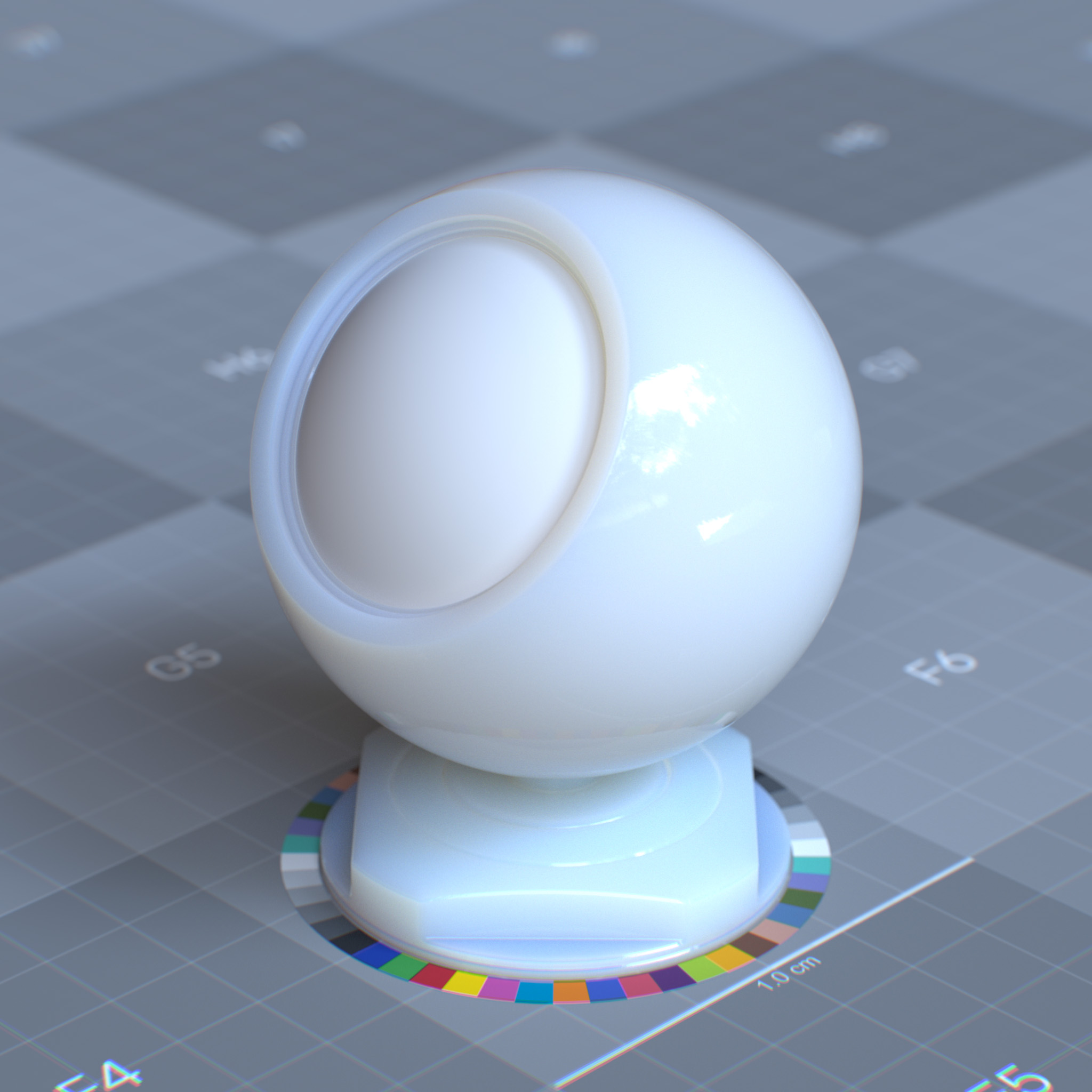
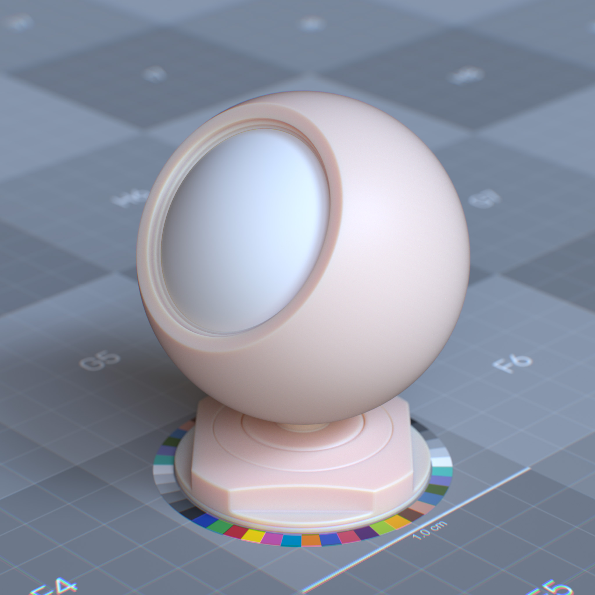
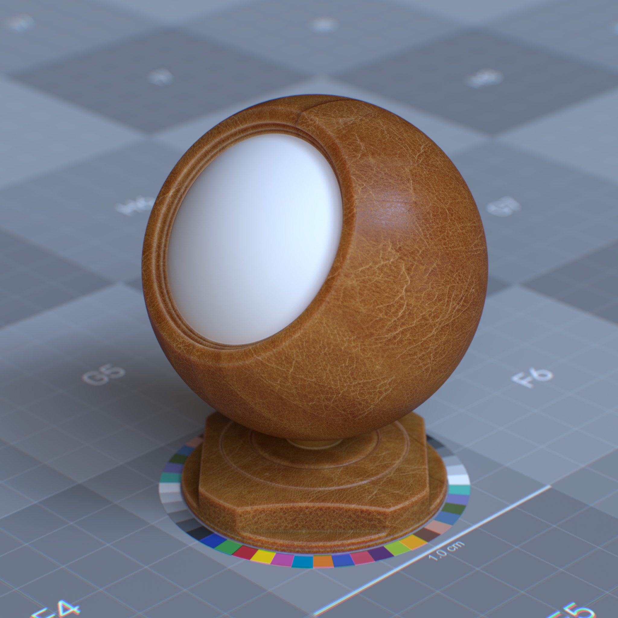
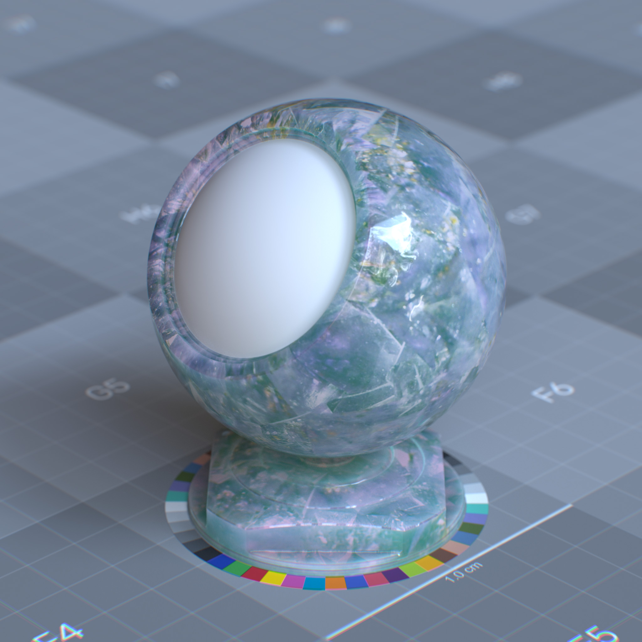
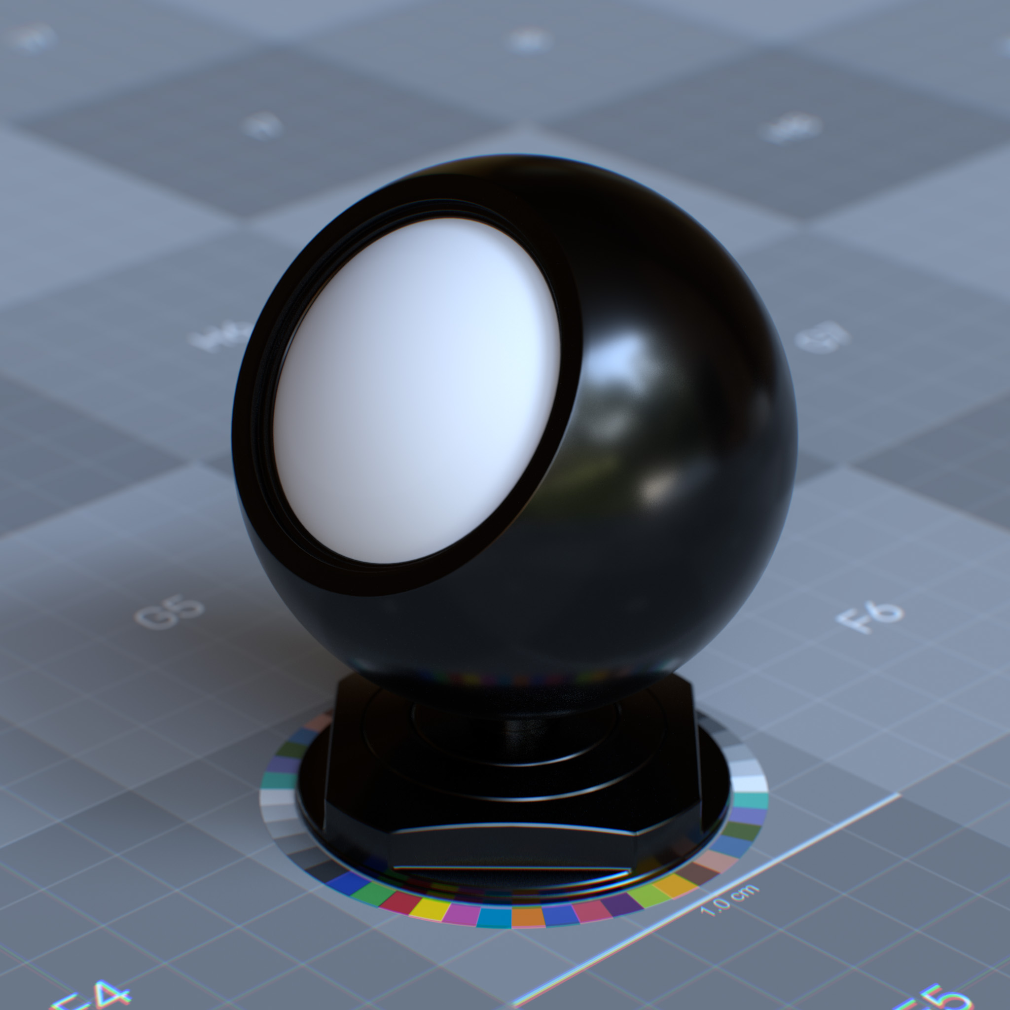
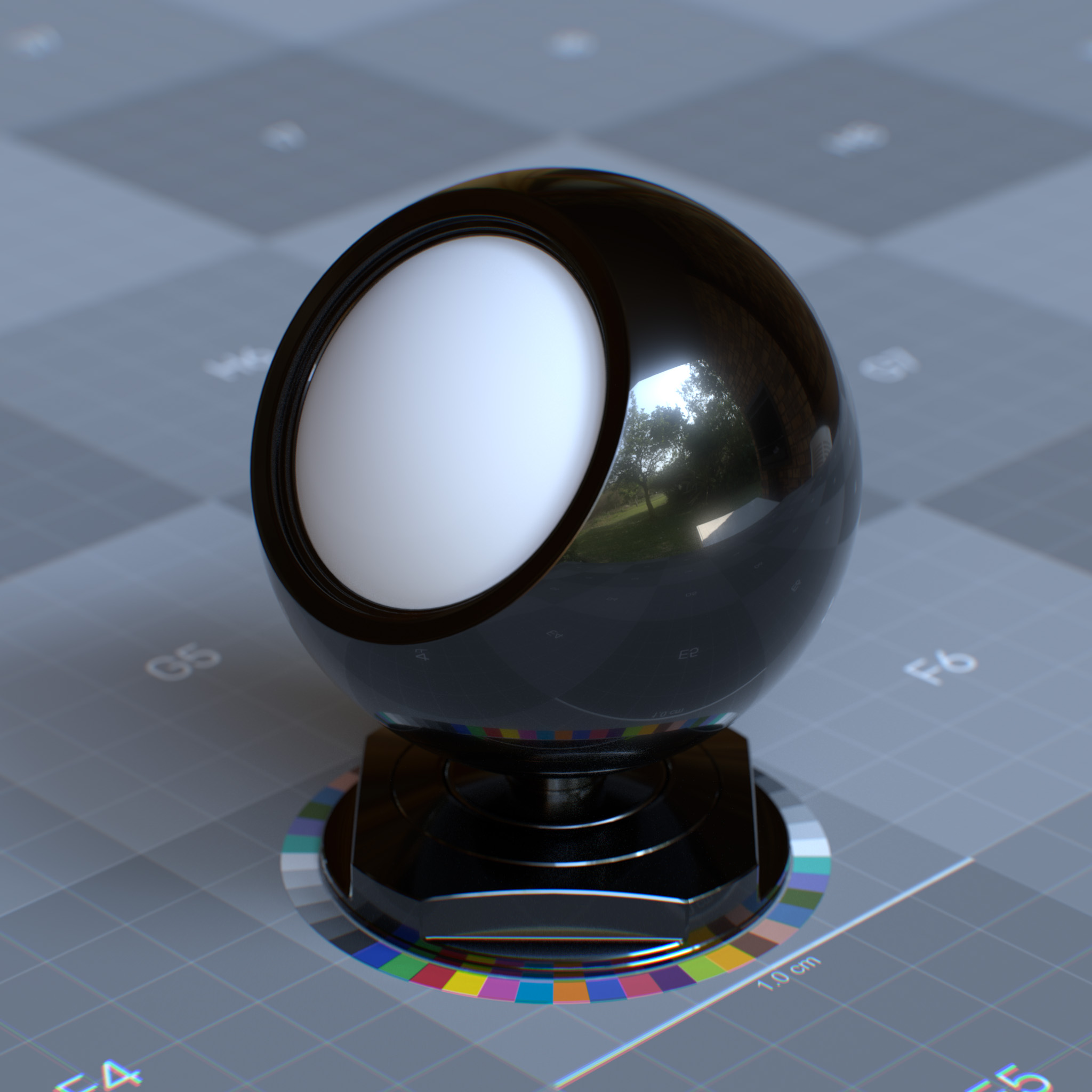
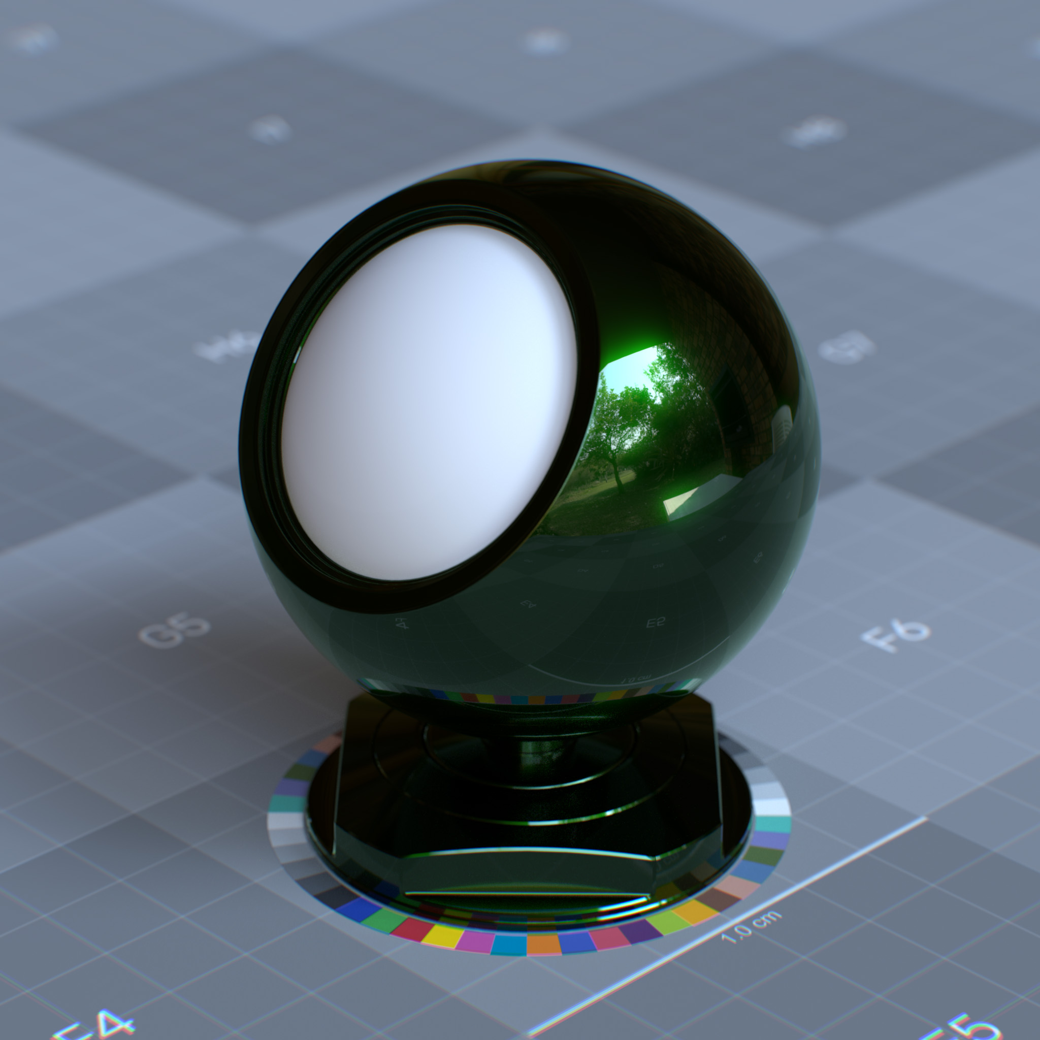
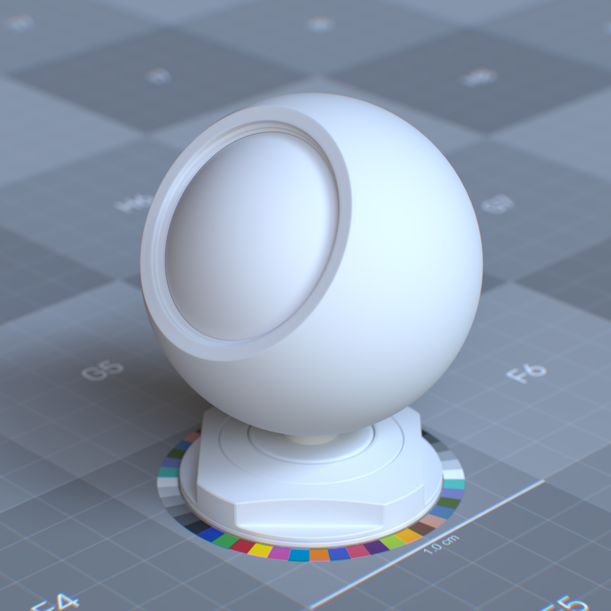
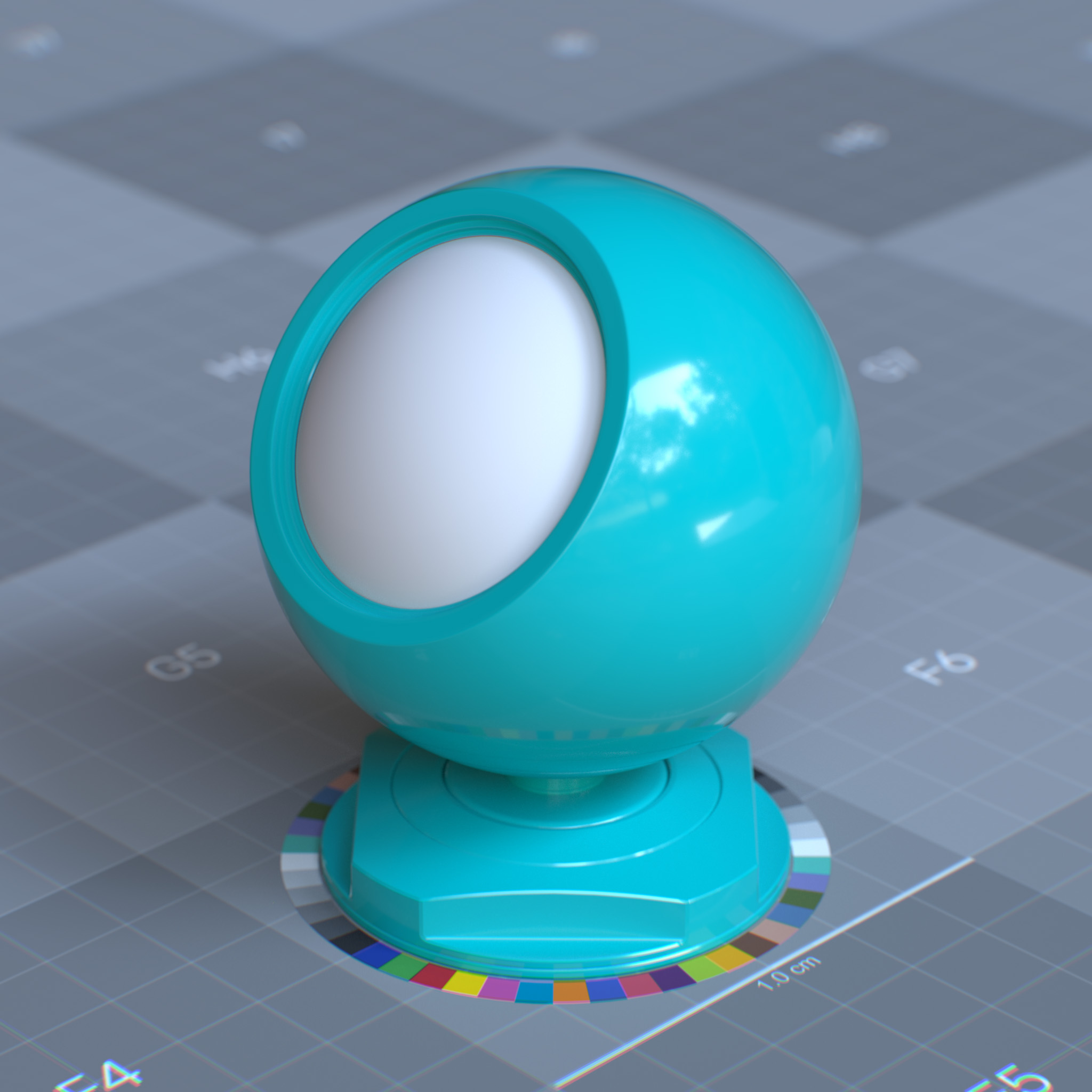
OmniSurfaceBase and OmniSurfaceLiteBase#
OmniSurfaceBase and OmniSurfaceLiteBase are physically-based materials designed based Autodesk® Standard Surface, capable of modeling a wide variety of surface appearances, including plastic, concrete, water, car paint, skin, foliage, foam, wax, wood, velvet, etc. This documents the base features. The non-base materials have direct texture mapping parameters and are standalone uber materials.
OmniSurfaceBase and OmniSurfaceLiteBase come with a small set of parameters with intuitive meanings, ranges, and predictable results.
Note
For creating simple materials, the use of OmniSurfaceLiteBase is encouraged. In general, OmniSurfaceLiteBase renders faster.
Parameters#
Base
The Base color of a surface before lighting calculations. Base represents only the pure color reflection of a surface, excluding lighting, shadows, or reflective properties.
Parameters
Display Name |
Name |
Type |
Default |
|---|---|---|---|
Weight |
diffuse_reflection_weight |
float |
0.8 |
Color |
diffuse_reflection_color |
color |
1.0, 1.0, 1.0 |
Diffuse Roughness |
diffuse_reflection_roughness |
float |
0.0 |
metalness |
metalness |
float |
0.0 |
This layer models the base layer, a statistical mix between diffuse reflection and diffuse transmission components.
Weight
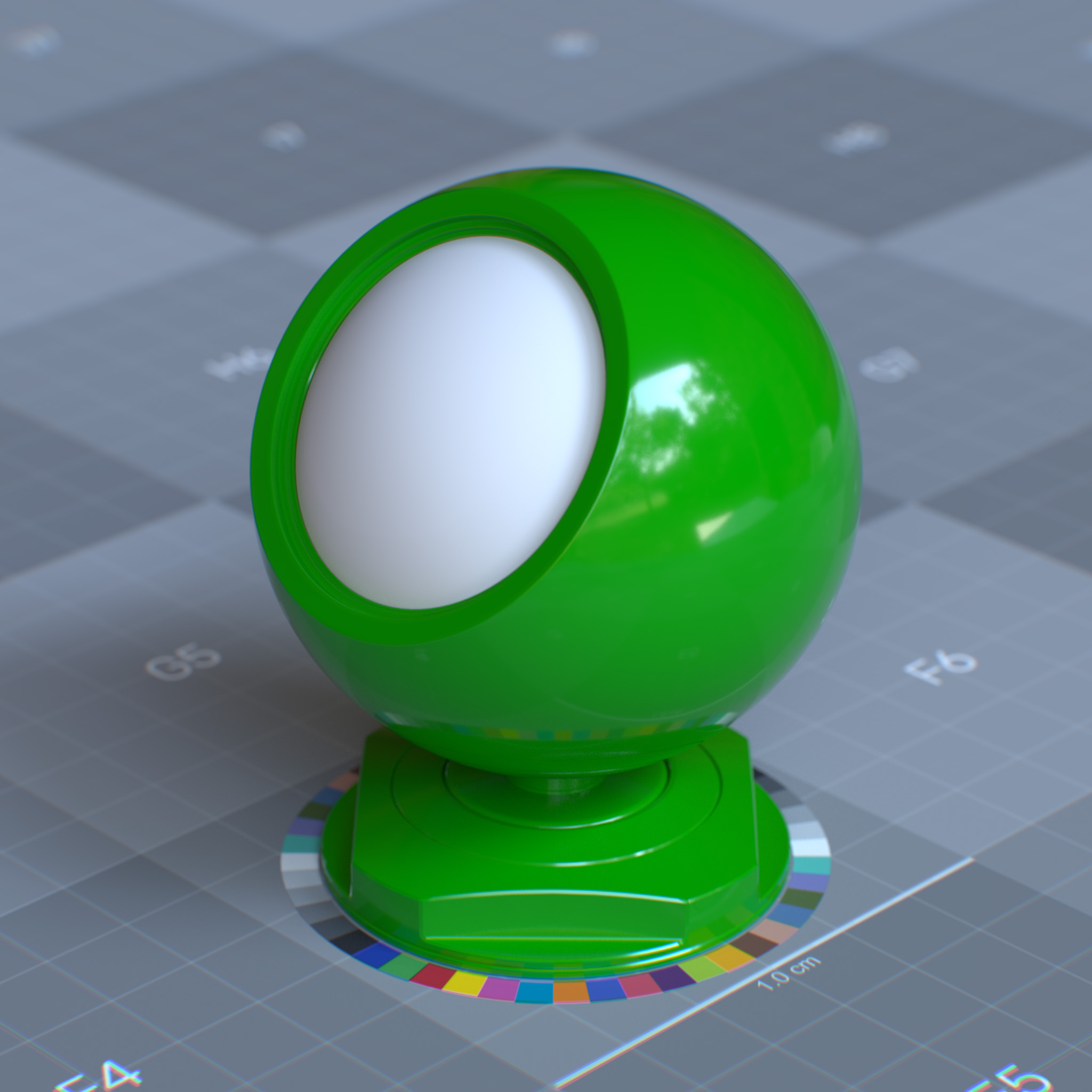
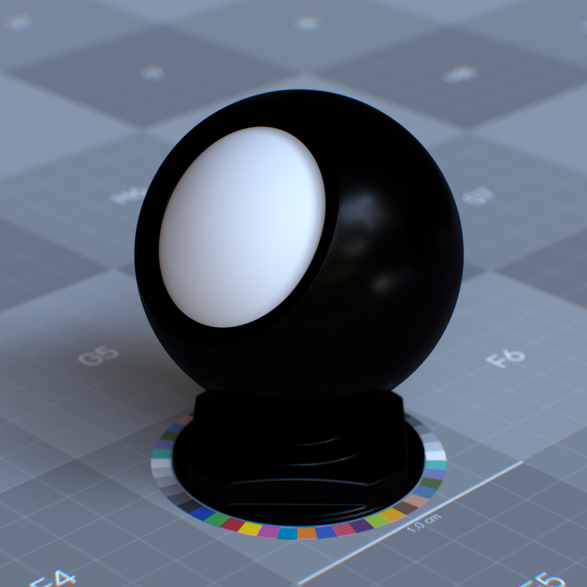
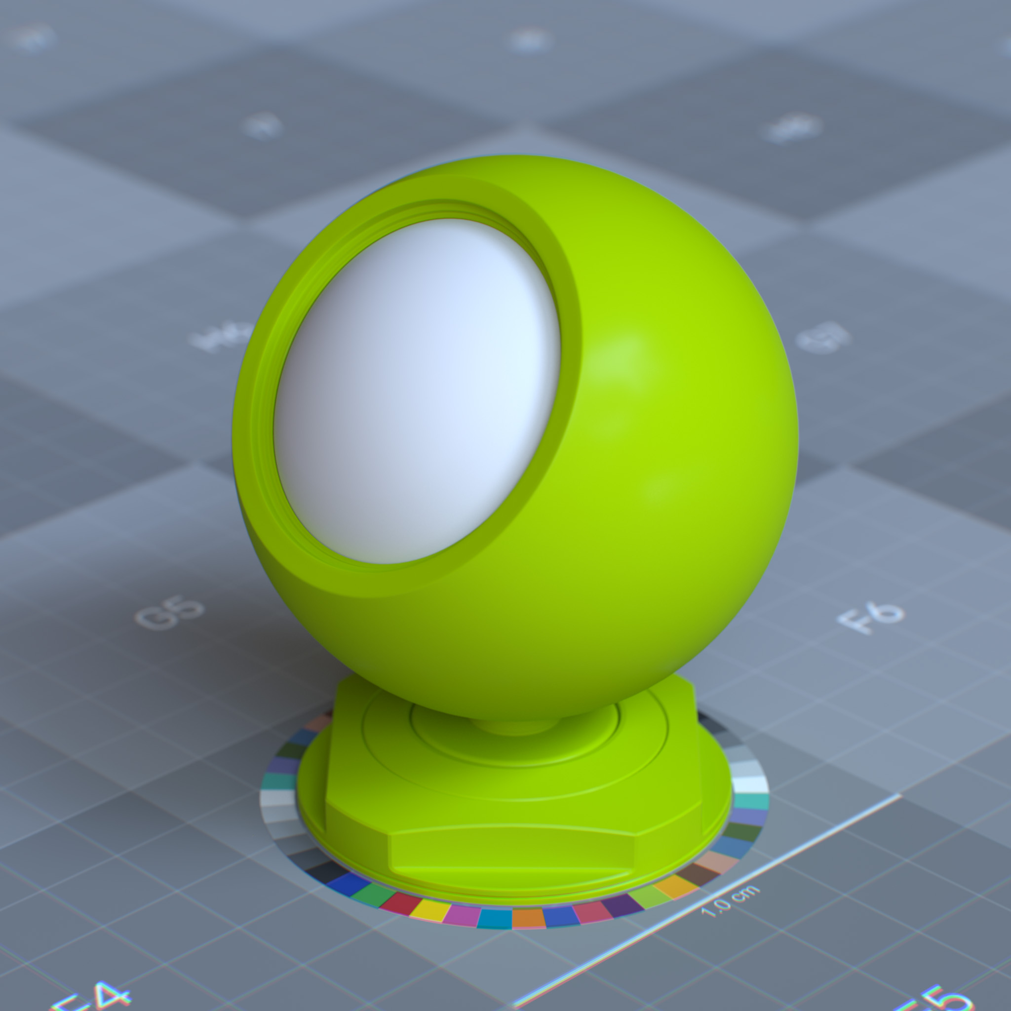
This parameter sets the weight of diffused reflection or metallic reflectance.
|
|
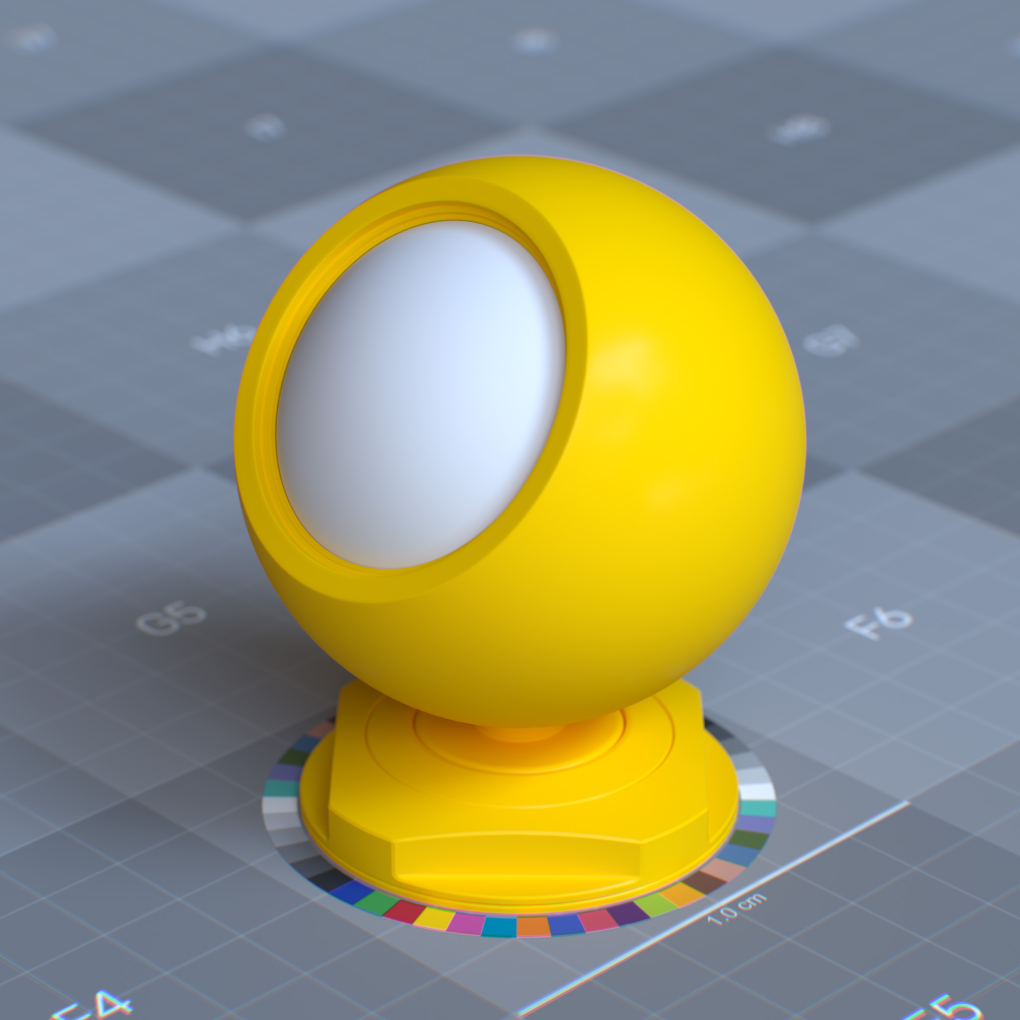
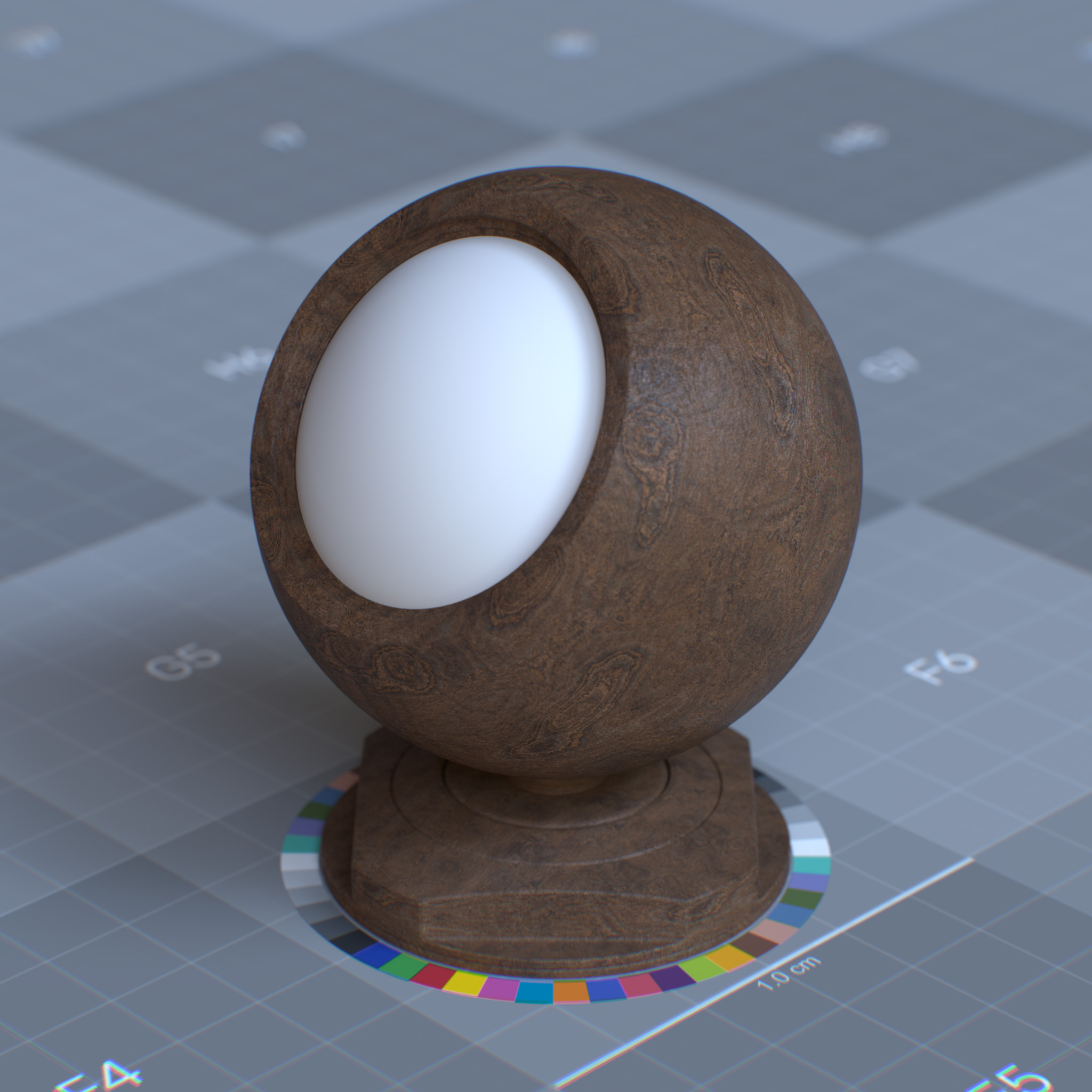
Color
This parameter sets diffuse reflection color of the dielectric surface or reflectance value of metallic surface by the probability that light is reflected or transmitted for each wavelength.
|
|
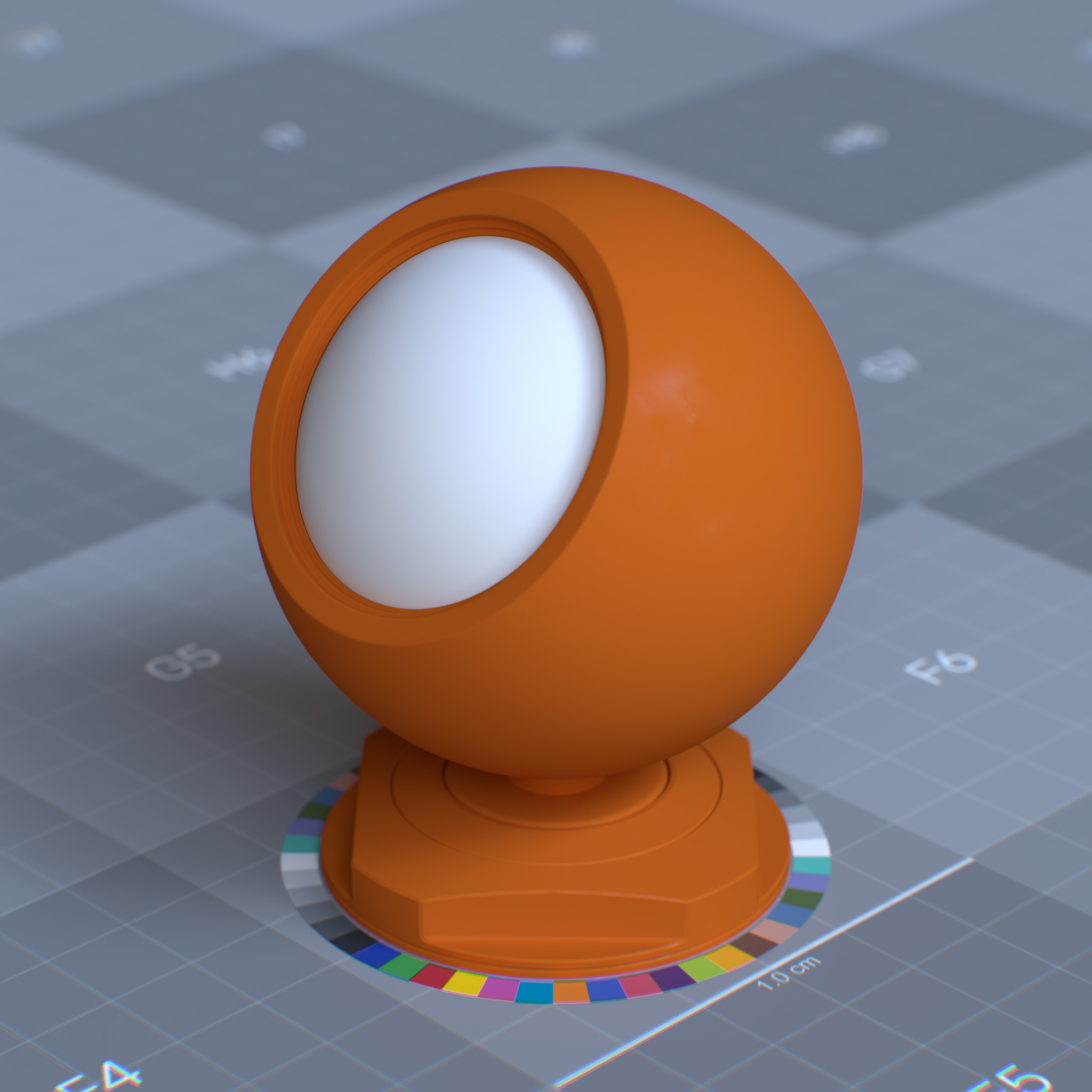
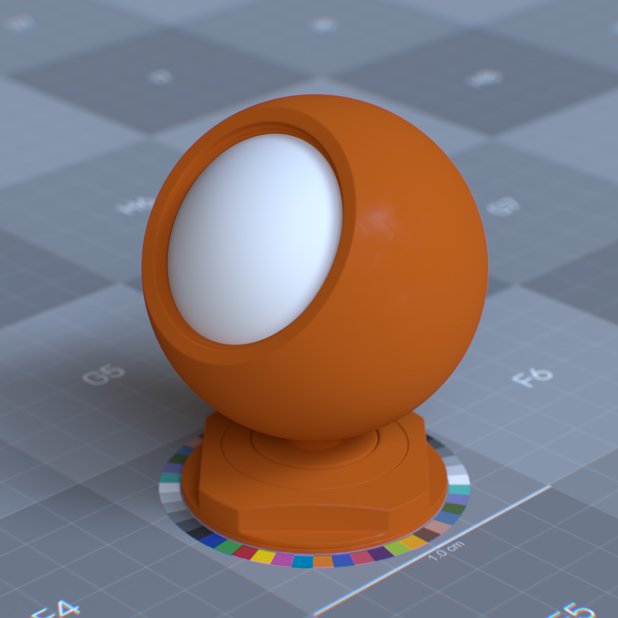
Diffuse Roughness
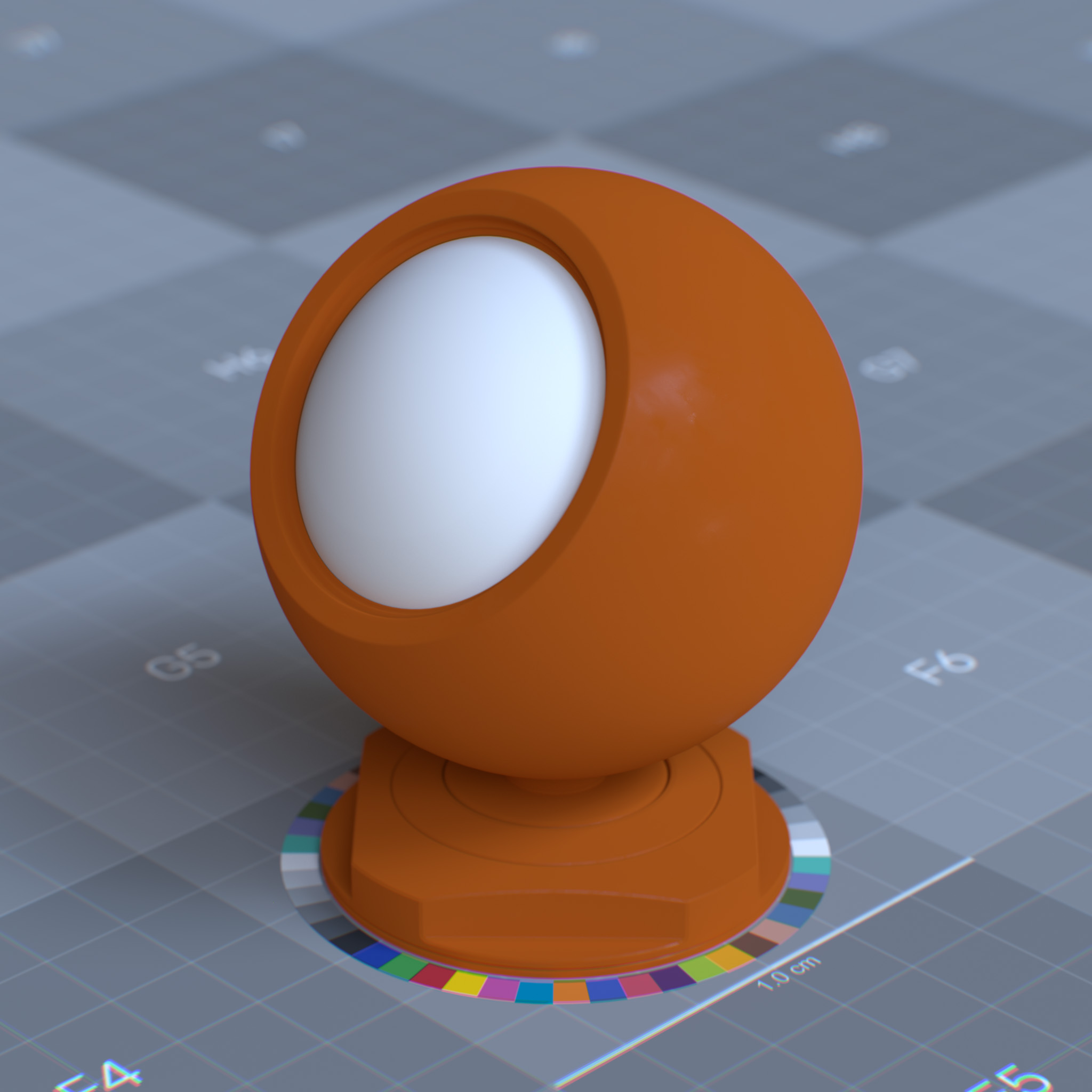
Oren-Nayar surface roughness coefficient, simulating view-dependent diffuse reflection. At 0.0, the surface behaves similarly to a fully Lambertian reflection. Higher values are suitable for powdery surfaces like dust, sand, dried clay, concrete, etc.
|
|
|
Metalness
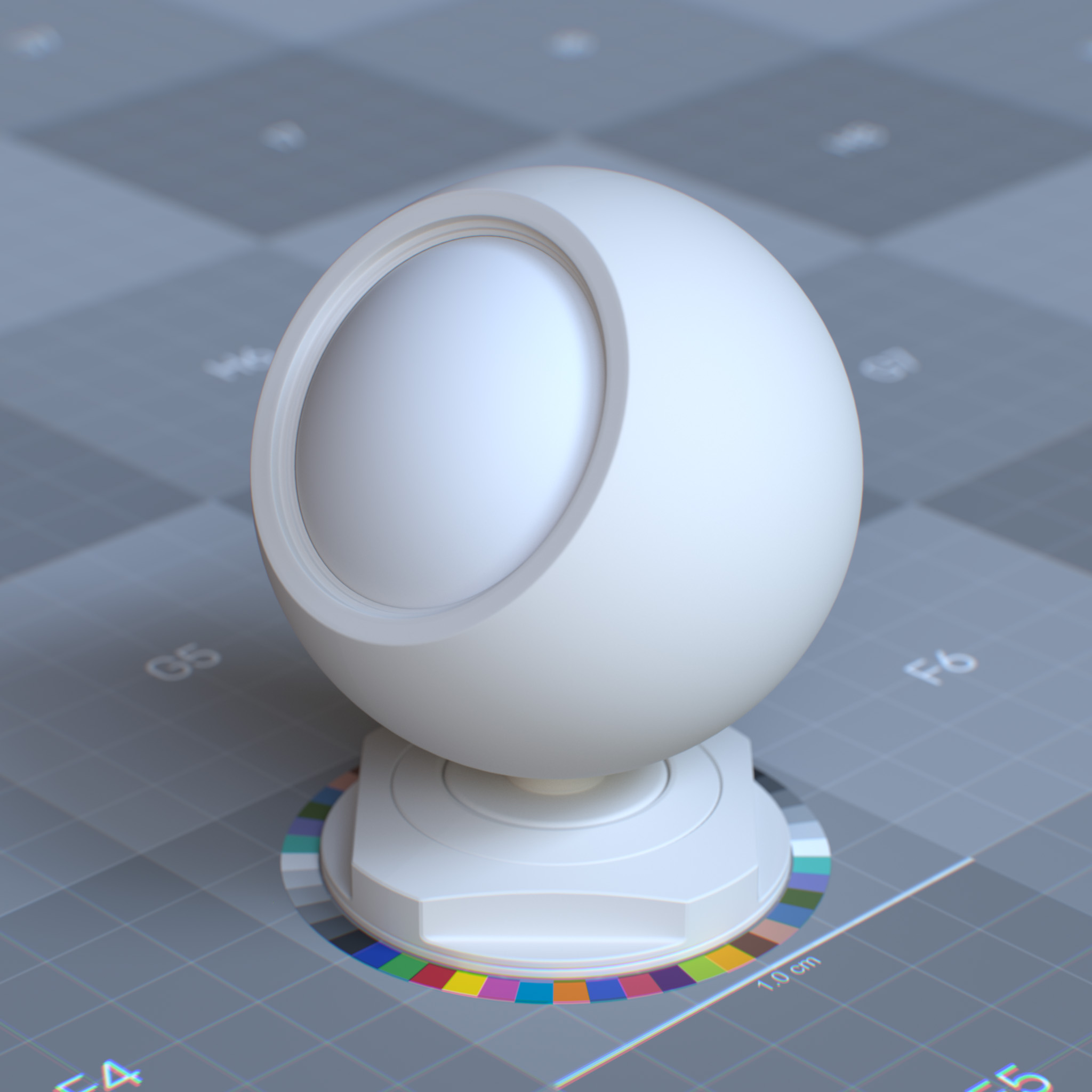
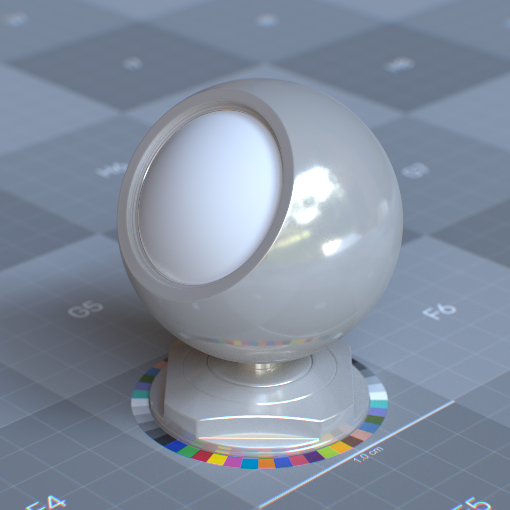
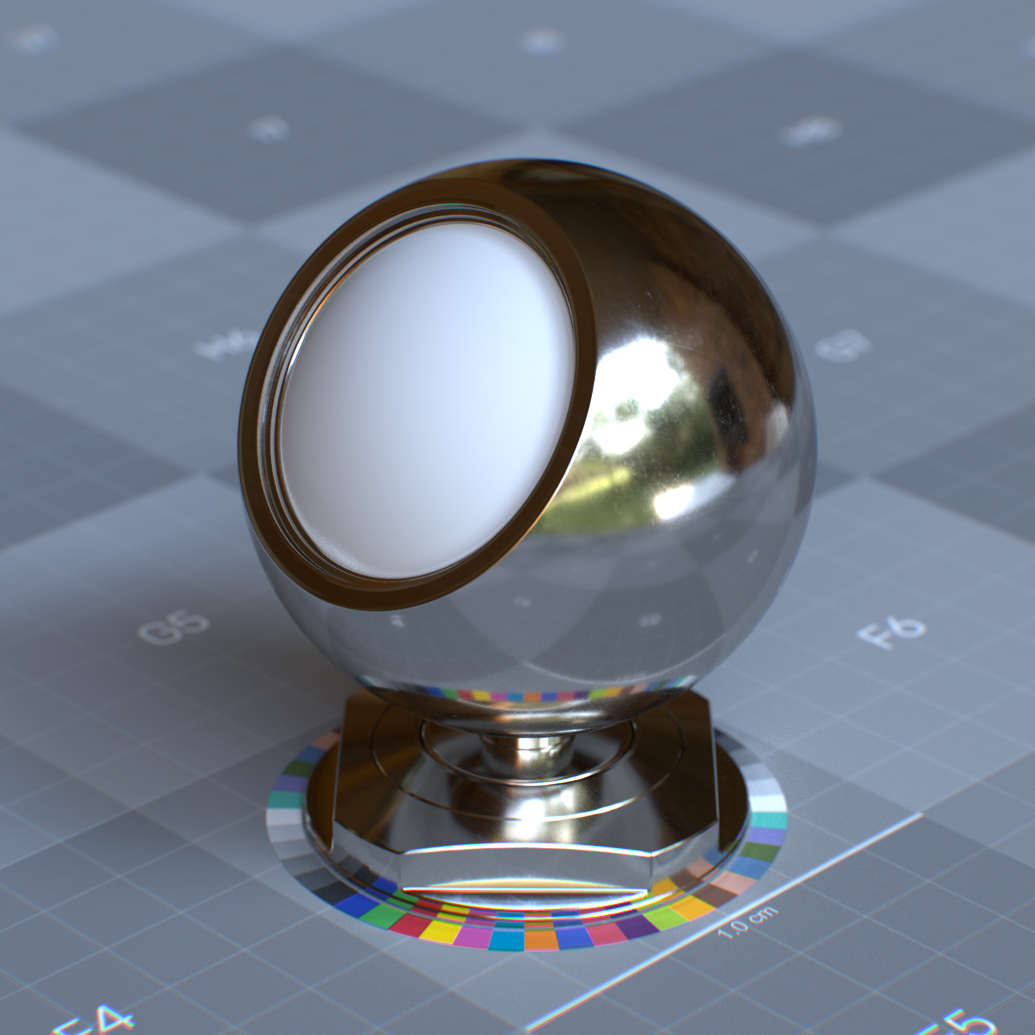
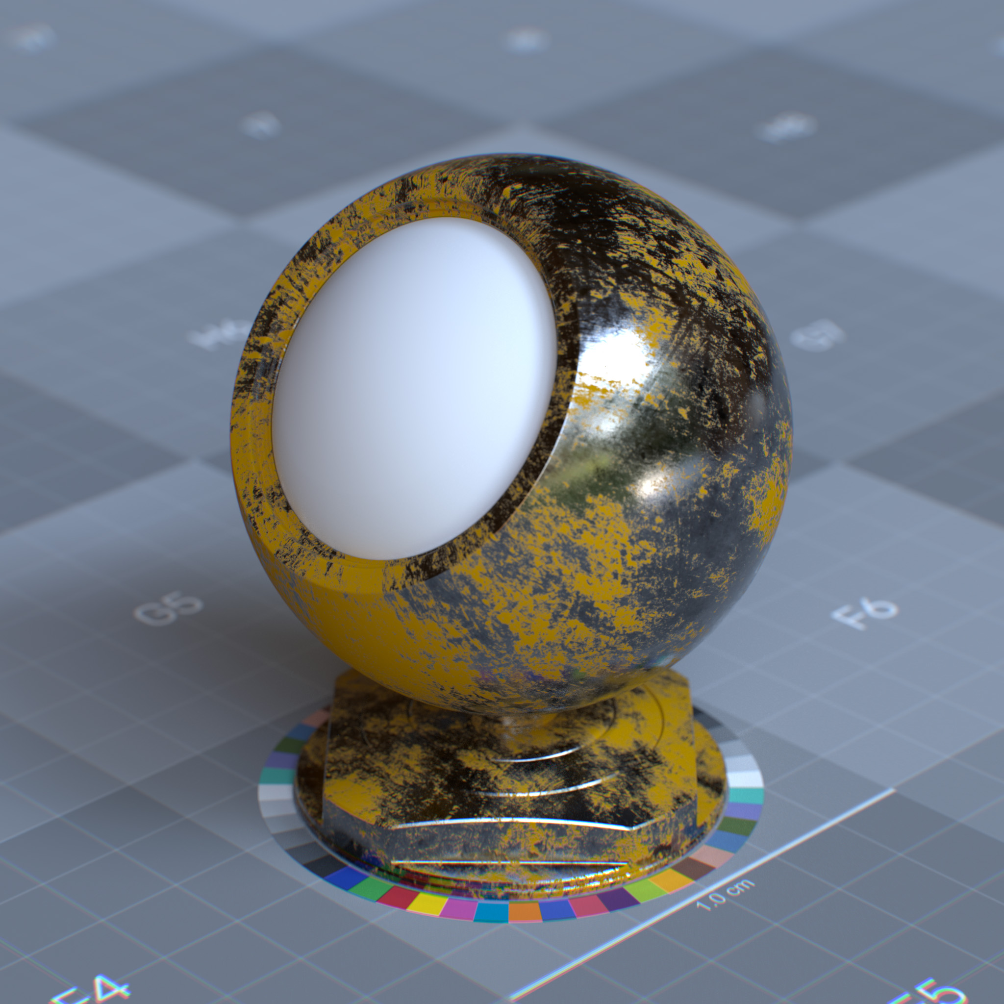
At 0.0, the material consists of a diffuse or transmissive base layer, with a specular reflection layer on top. When set to 1.0, the surface behaves like a metallic surface. For fully reflective metal, one can set the base weight and metalness to 1.0 and decrease specular reflection roughness to 0.0. Metalness values between 0.0 and 1.0 can create surfaces like oxidized copper when some surface areas are reflective, and some areas are not.
|
|
|
|
The metallic reflection is modeled as a GGX microfacet conductor BRDF. The absorption coefficient and complex index of refraction are computed from the base color and the specular reflection color. The base color controls the metallic surface appearance, and specular reflection weight and specular reflection color parameters only affect the edge tint.
See Thin Film section for more information.
Specular
The specular component controls direct surface reflections in materials. It simulates mirror-like behavior by defining reflection intensity, surface micro-roughness, and angle-dependent reflectivity (Fresnel effect).
Parameters
Display Name |
Name |
Type |
Default |
|---|---|---|---|
Weight |
specular_reflection_weight |
float |
1.0 |
color |
specular_reflection_color |
color |
1.0, 1.0, 1.0 |
roughness |
specular_reflection_roughness |
float |
0.2 |
IOR Preset |
specular_reflection_ior_preset |
enum |
ior_custom |
IOR |
specular_reflection_ior |
float |
1.5 |
anisotropy |
specular_reflection_anisotropy |
float |
0.0 |
Rotation (rad) |
specular_reflection_anisotropy_rotation |
float |
0.0 |
This layer models a GGX microfacet dielectric BRDF under the coating layer. Due to Fresnel, this layer is not energy conversing. Thus the energy that is not reflected is transmitted to the underlying layers.
Weight
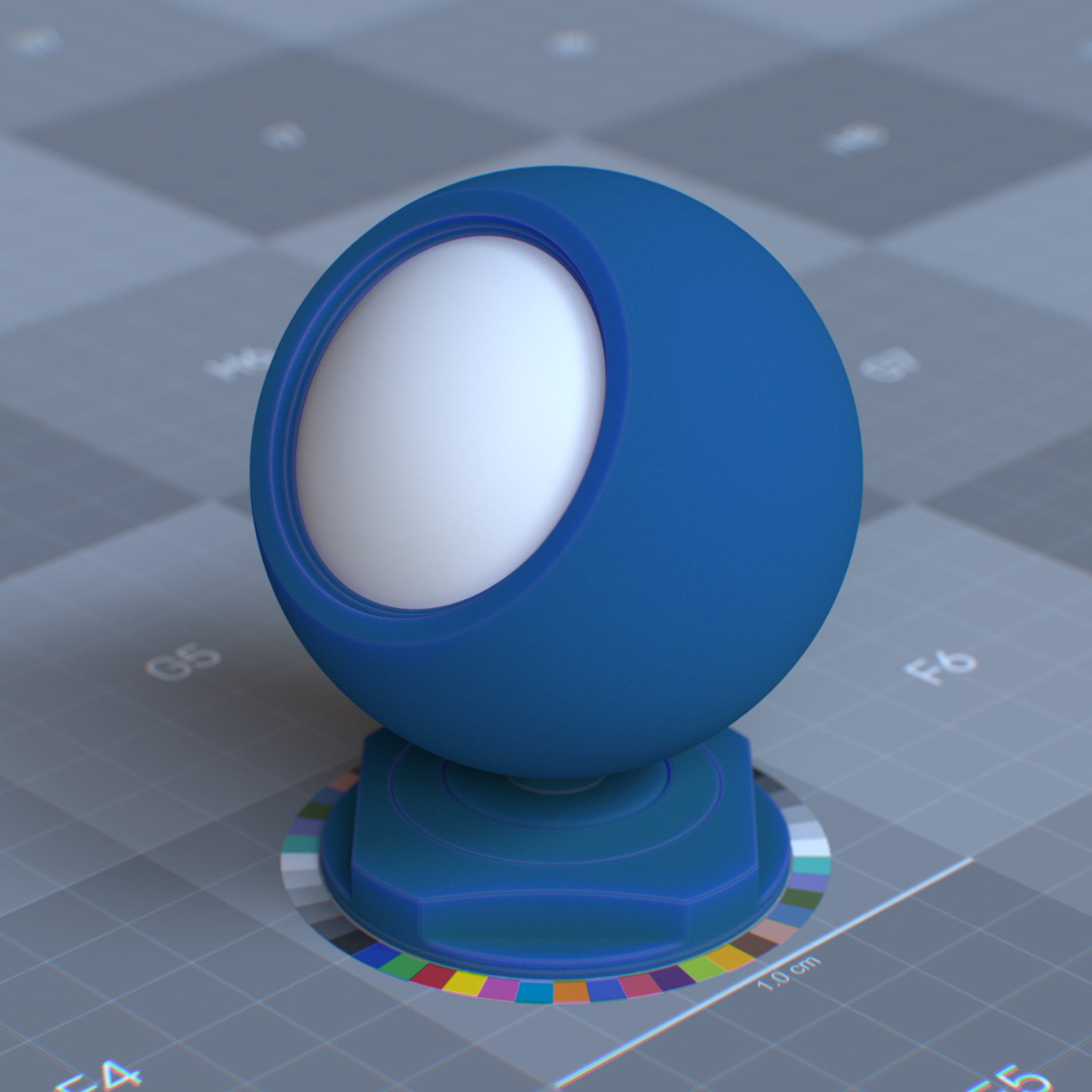
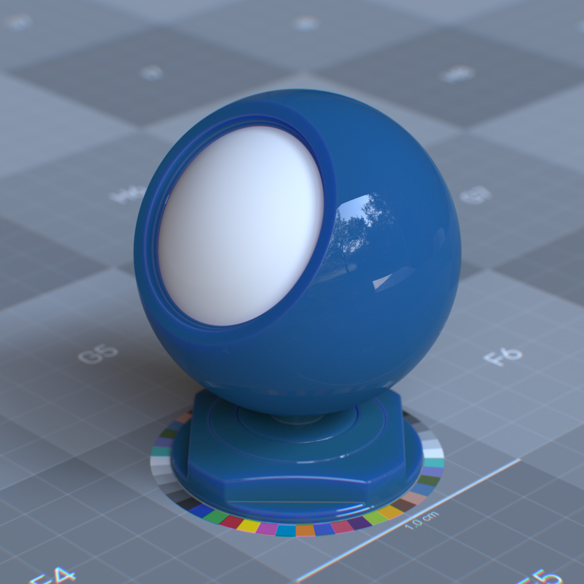
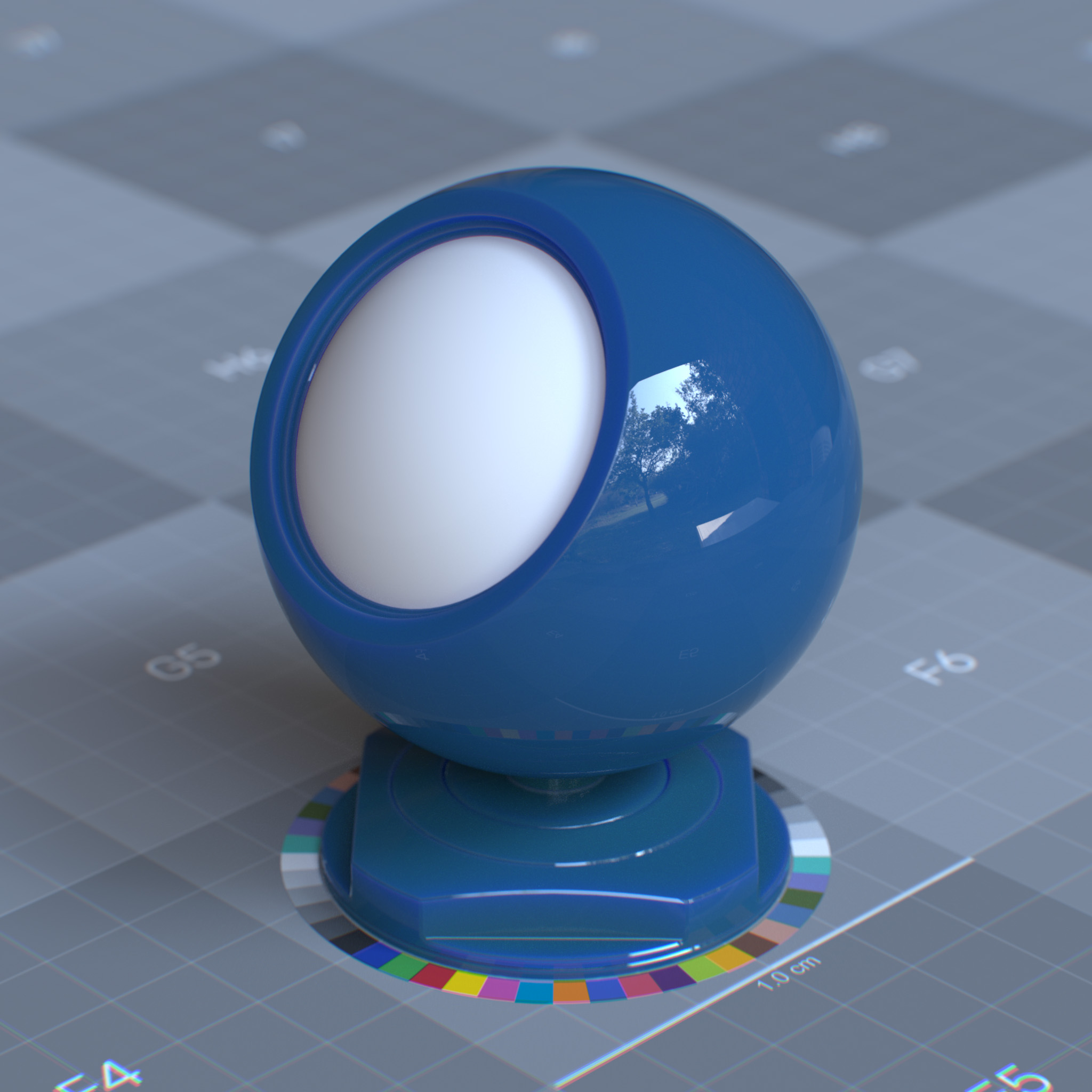
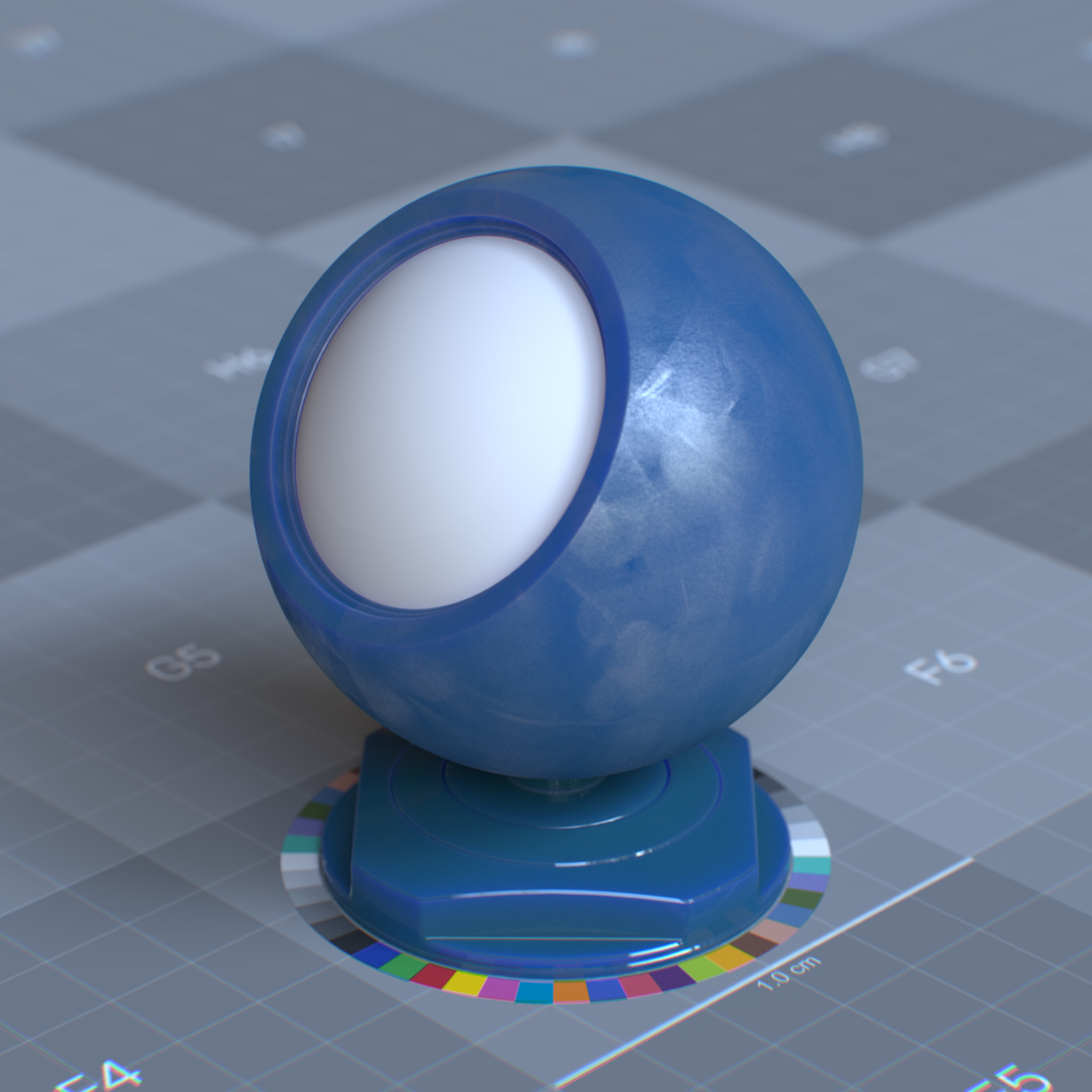
This parameter sets the amount of the specular reflection. Lowering this value increases light transmission through the object’s volume.
|
|
|
|
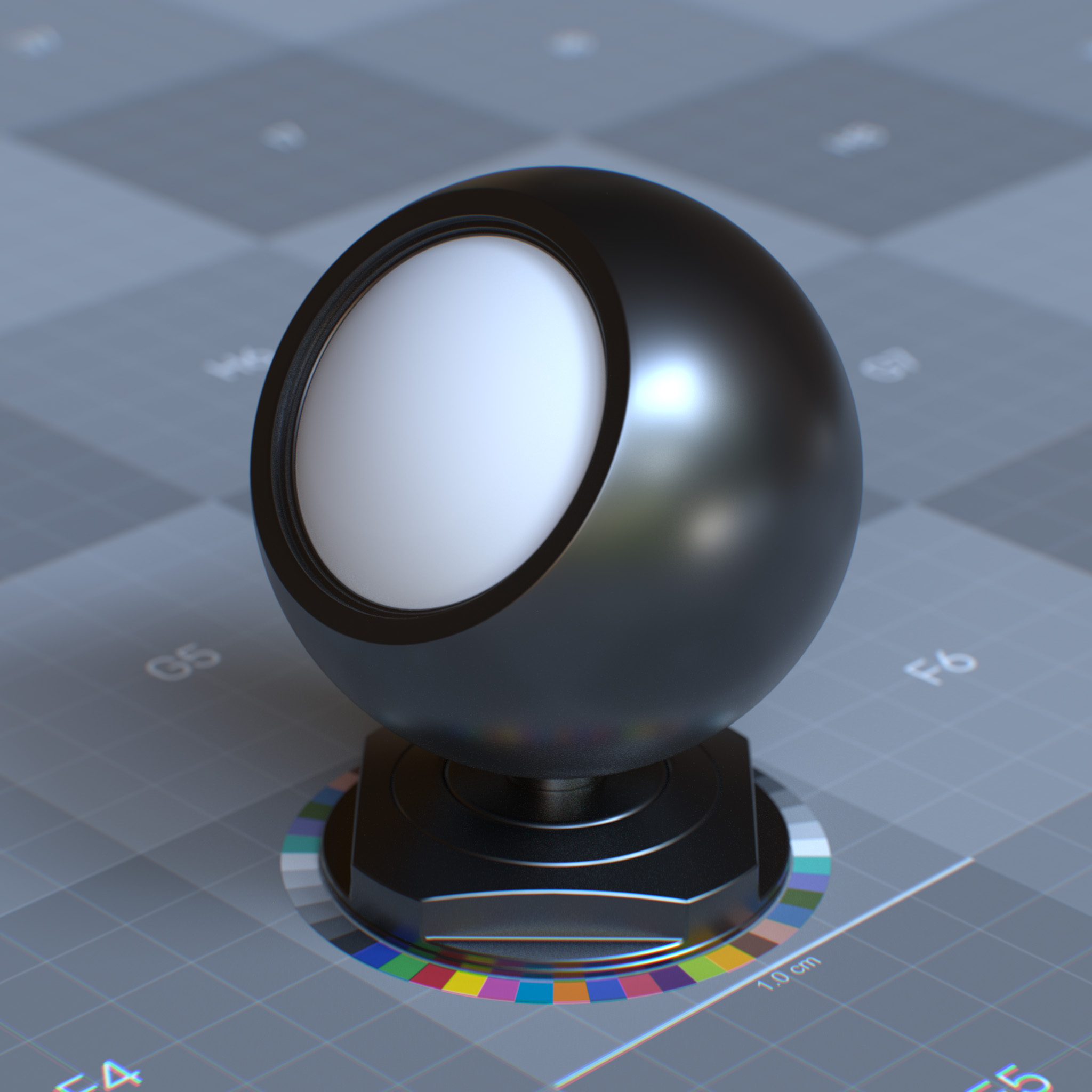
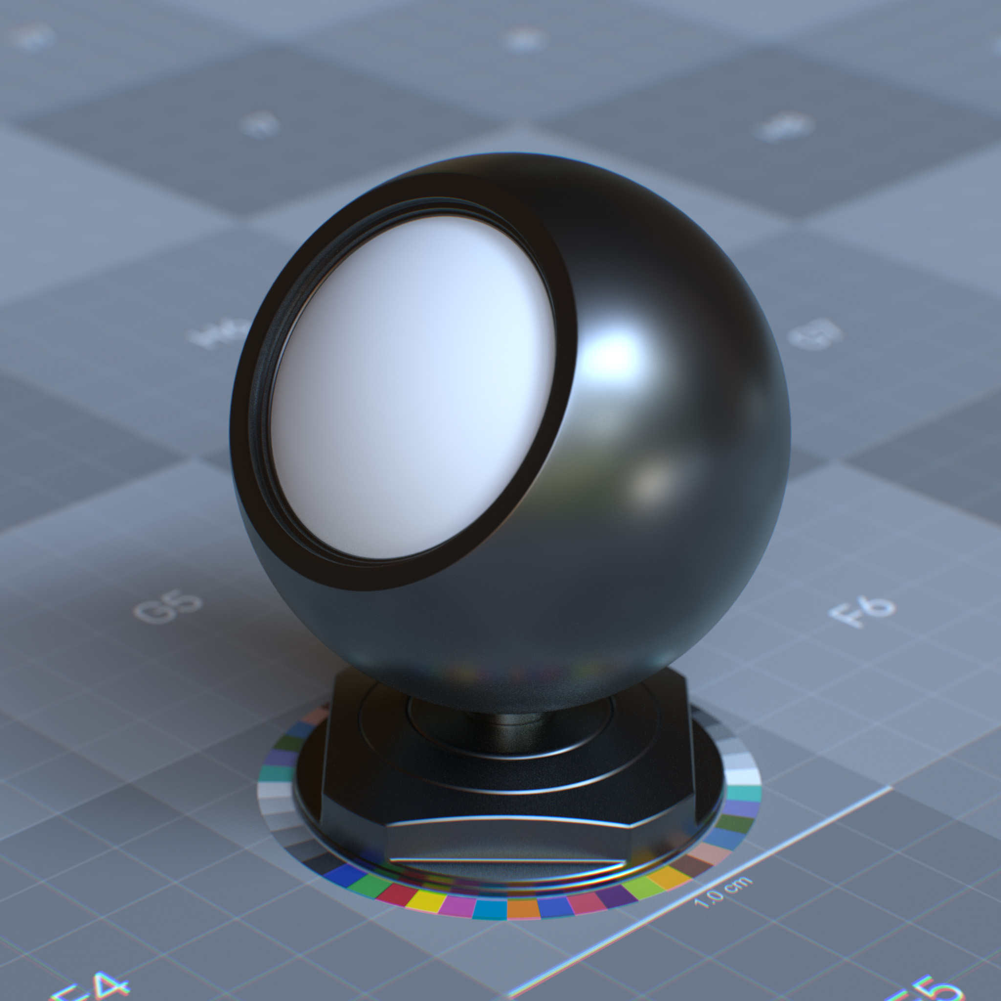
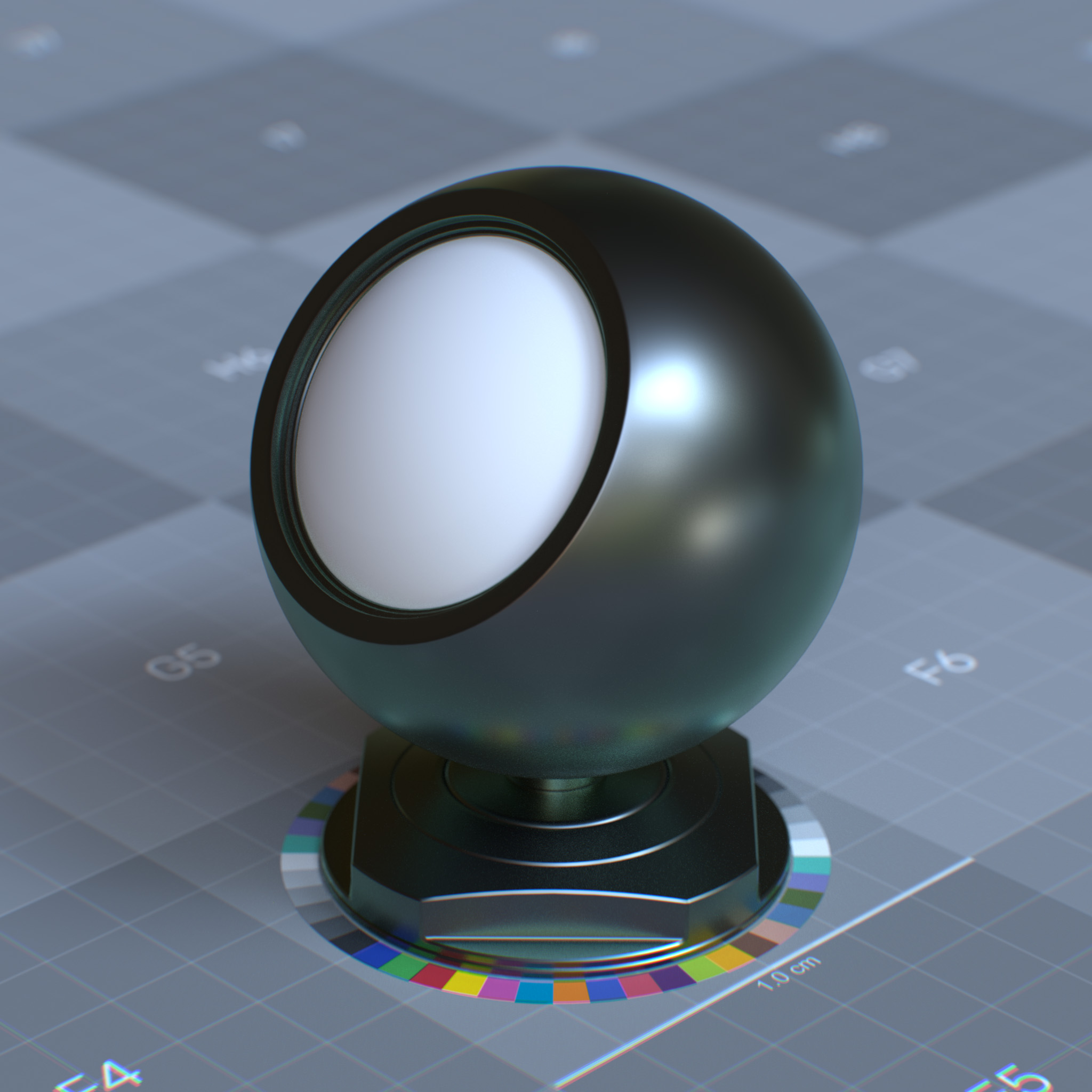
When Metalness is greater than 0.0, this parameter sets the edge tint weight for the metal surface.
|
|
|
Color
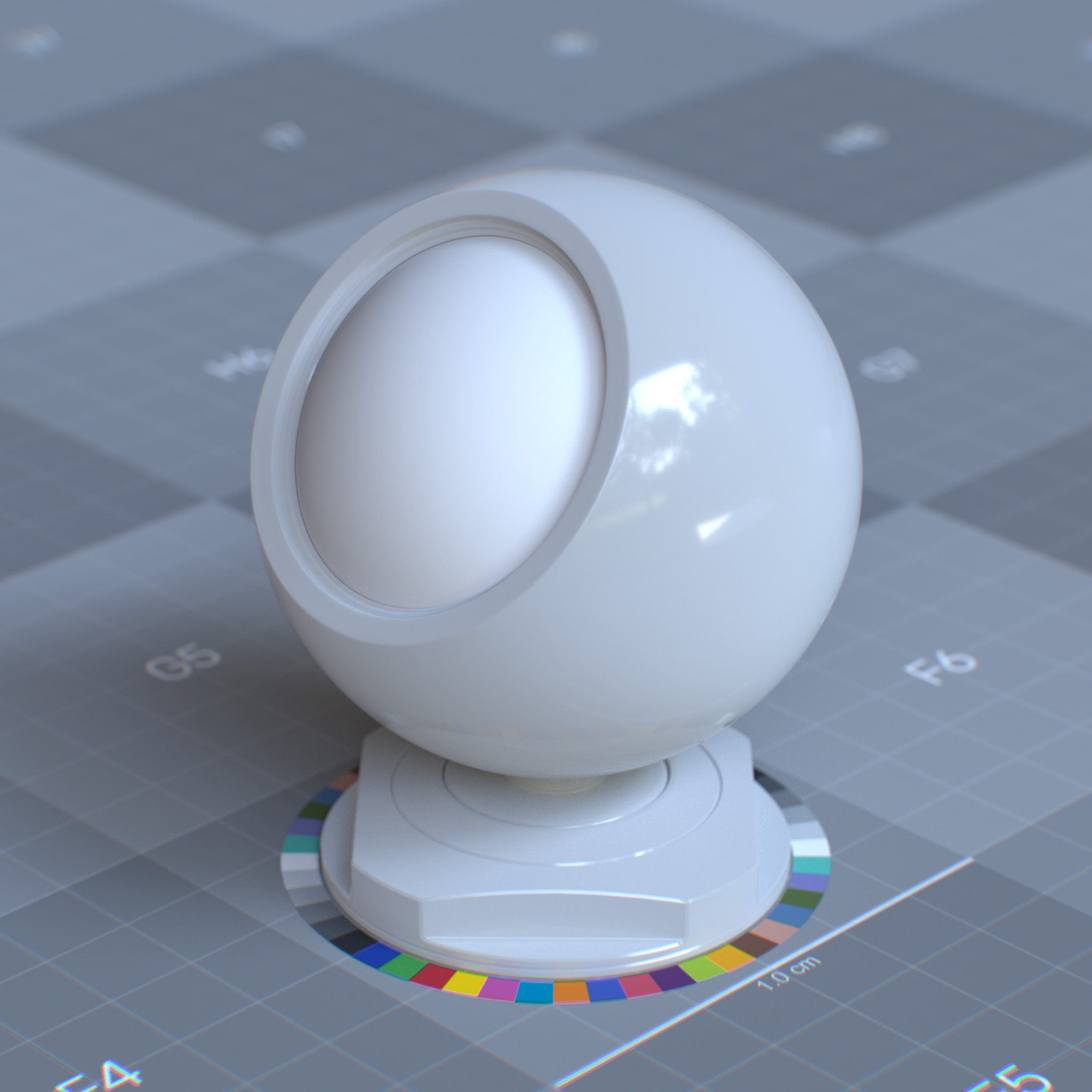
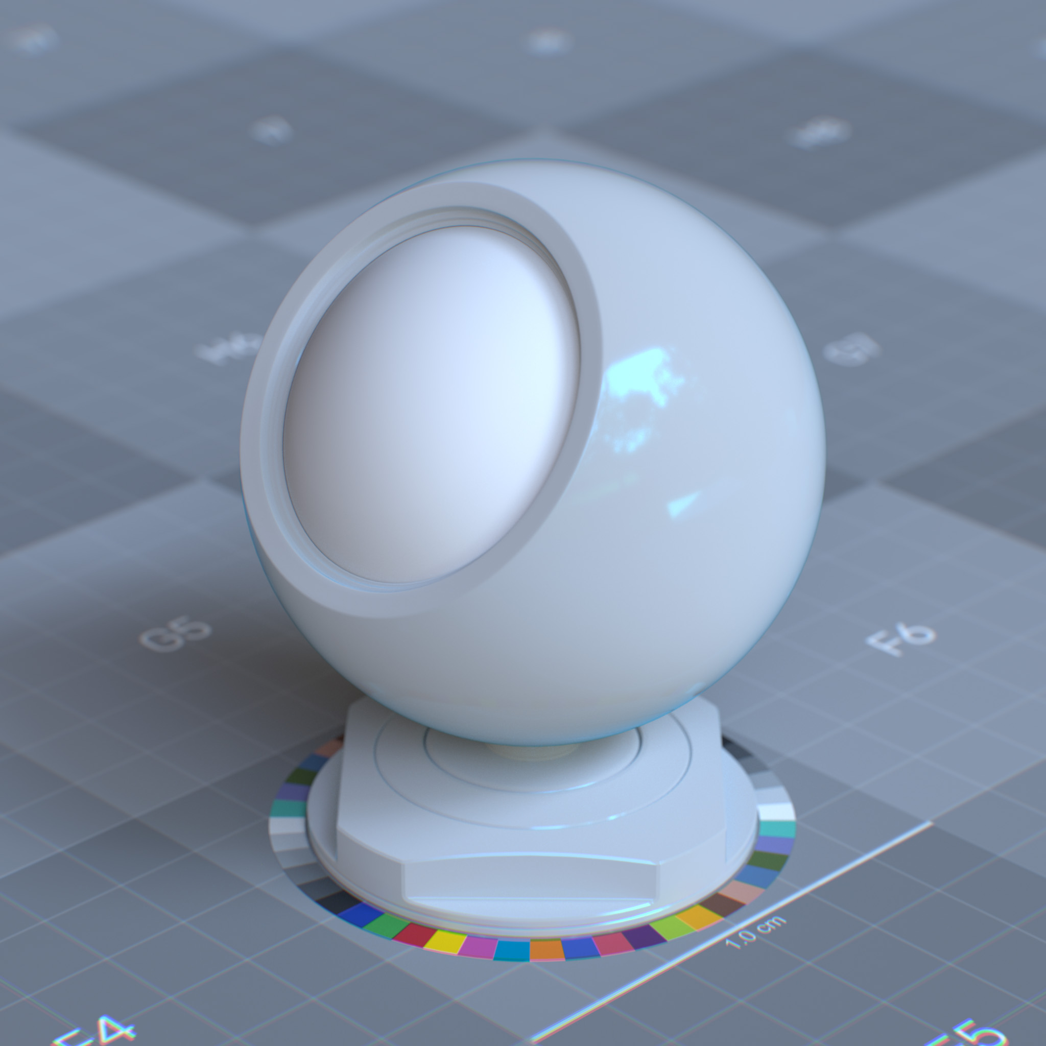
This parameter sets the color of the specular reflection. While some metallic (conductor) surfaces have colored specular reflections, dielectric surfaces have only achromatic specular reflections.
|
|
Tip
Setting the specular reflection color for dielectric surfaces other than white is not physically correct.
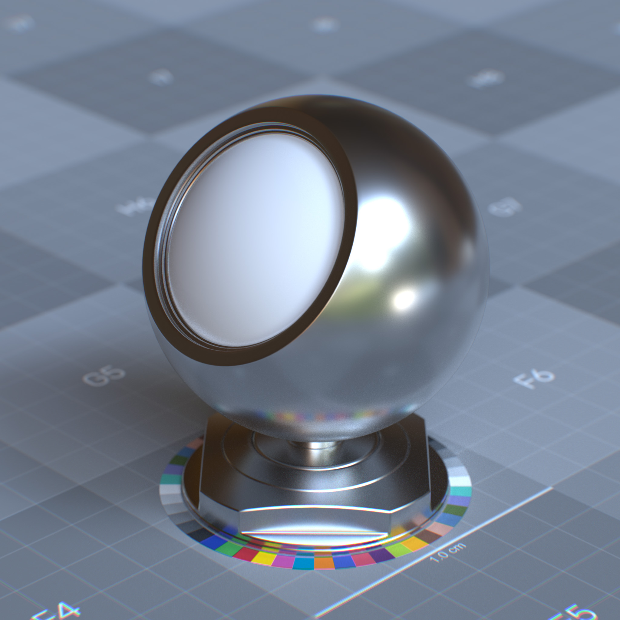
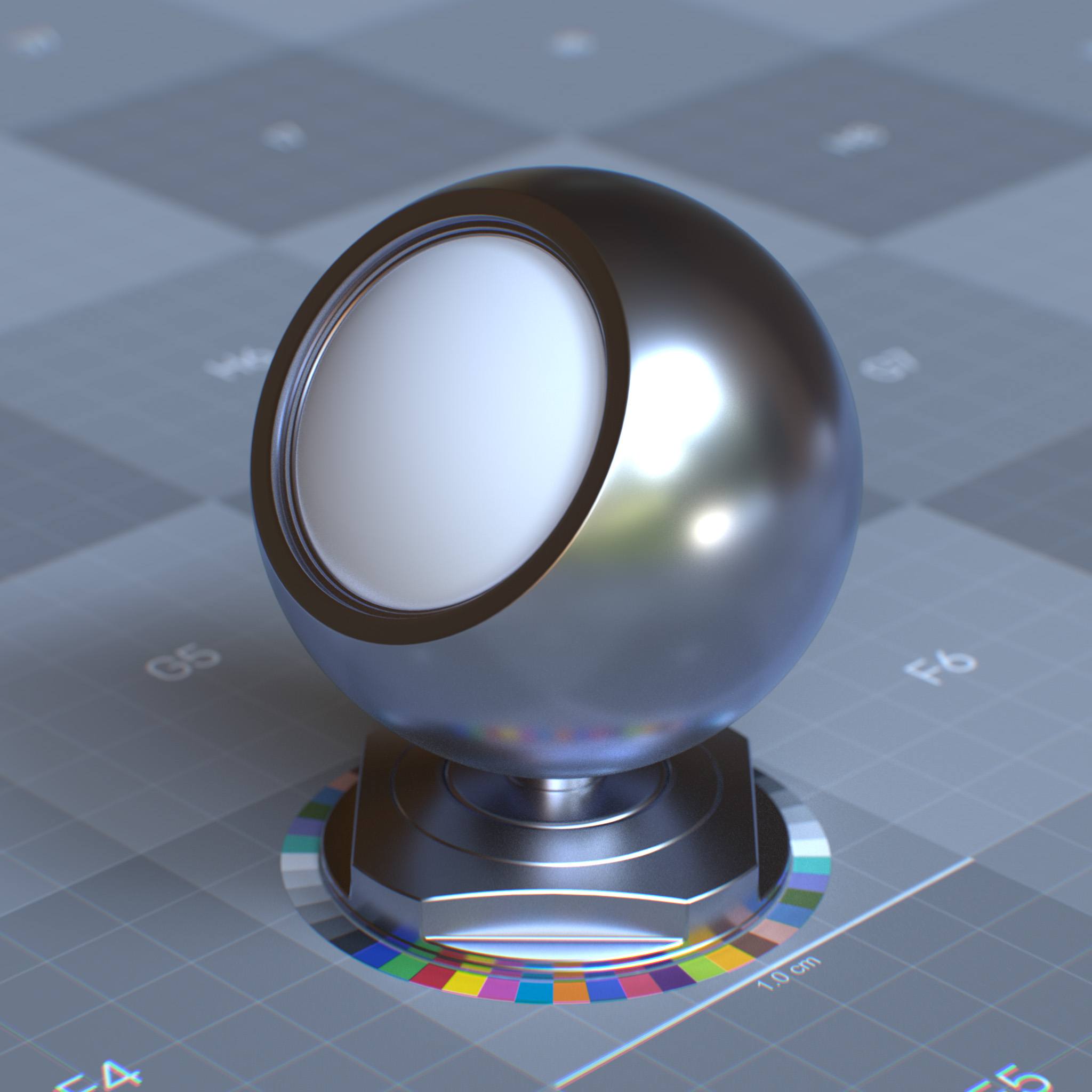
When metalness is greater than 0.0, this parameter sets the edge tint color.
|
|
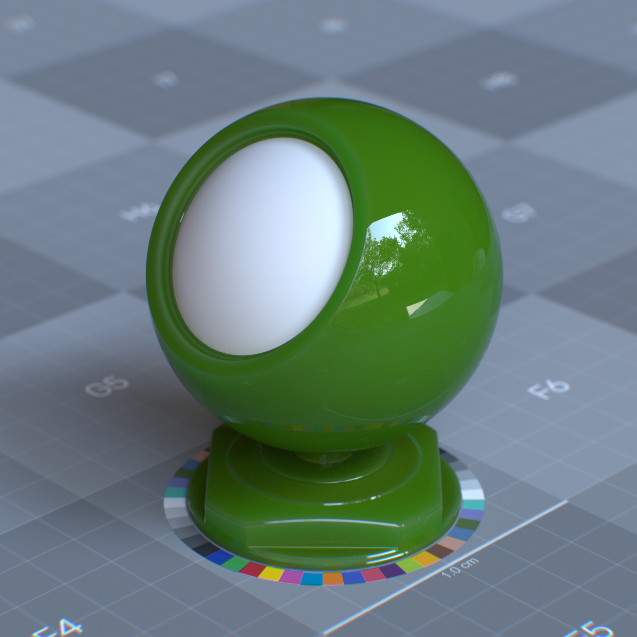
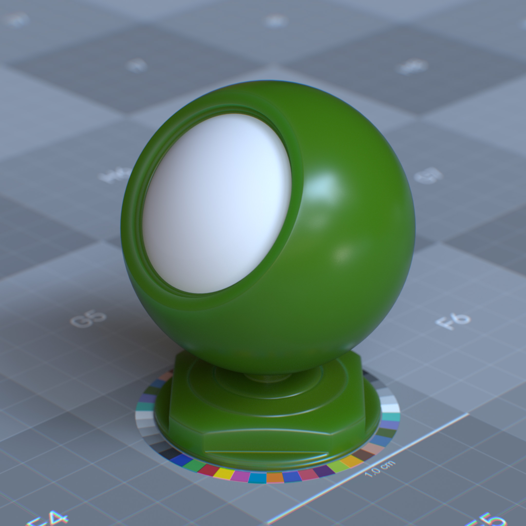
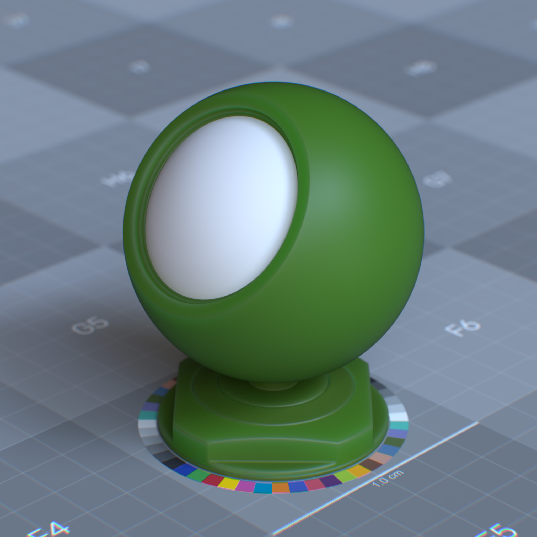
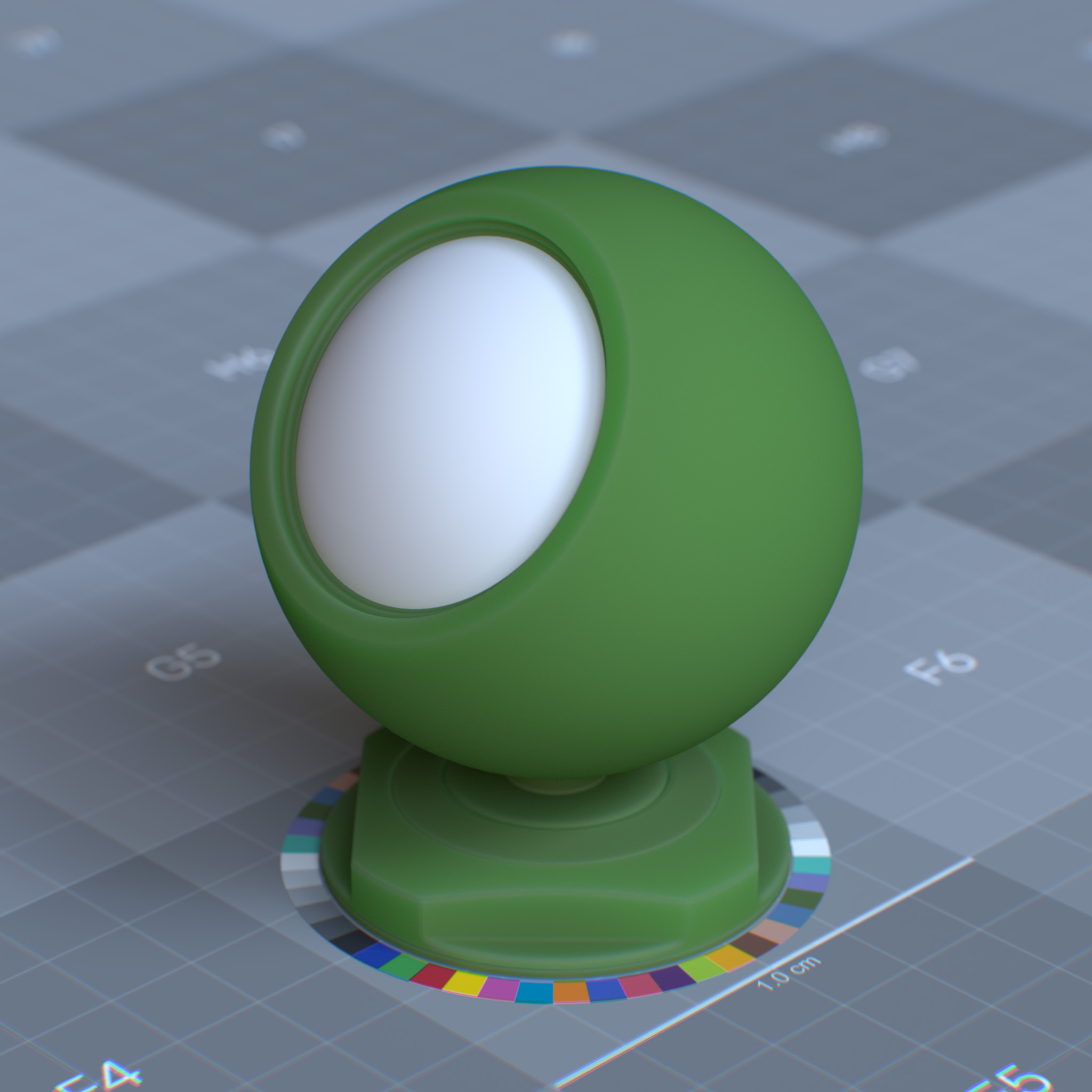
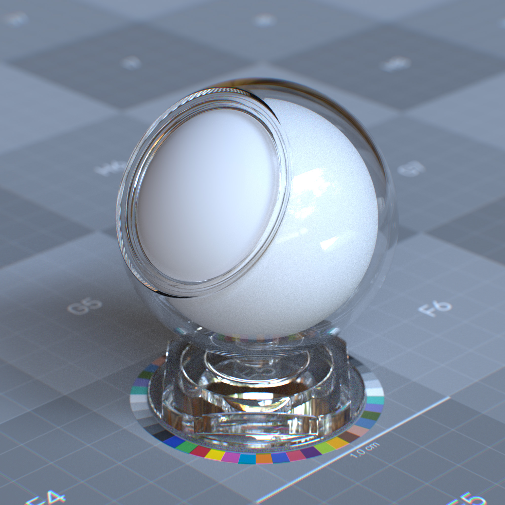
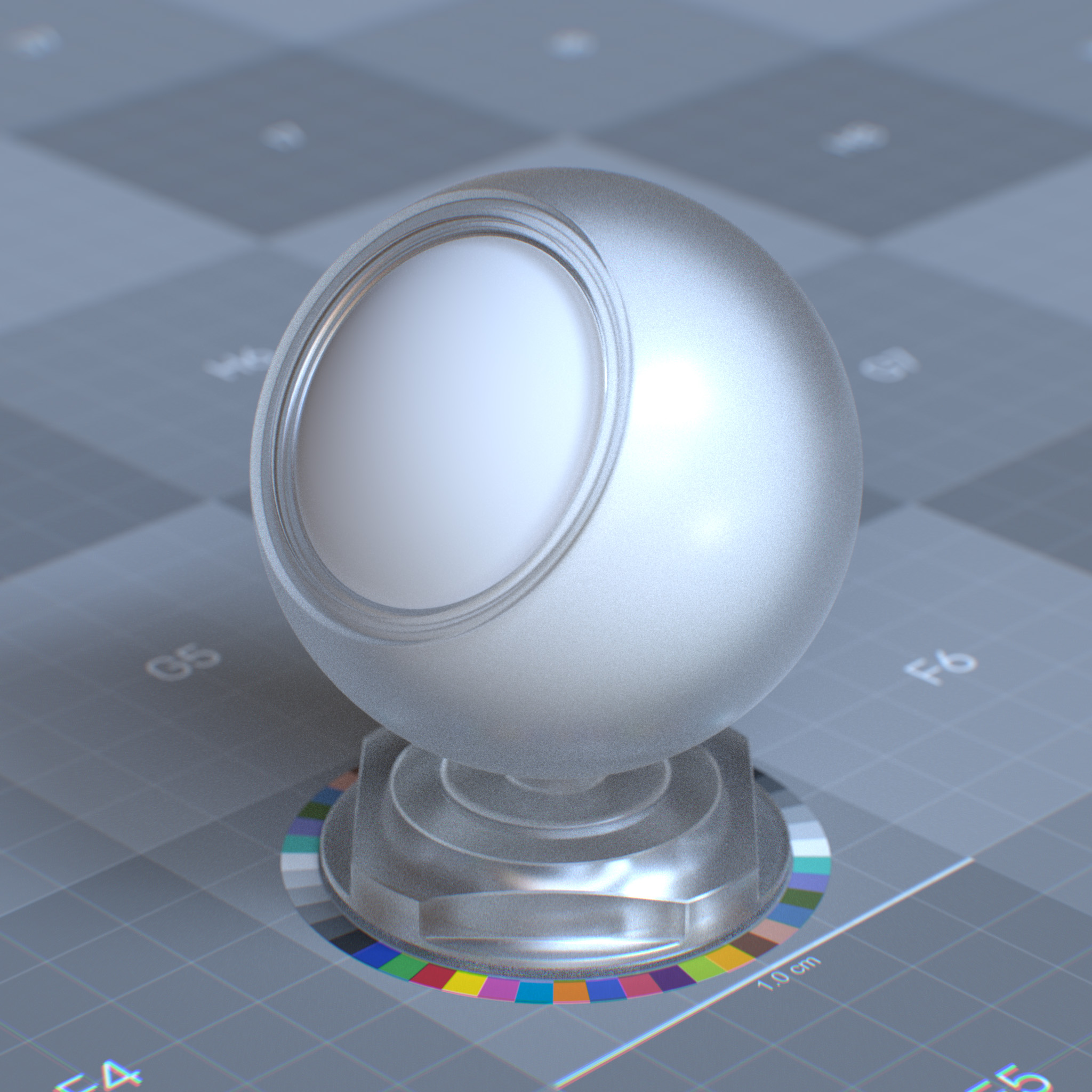
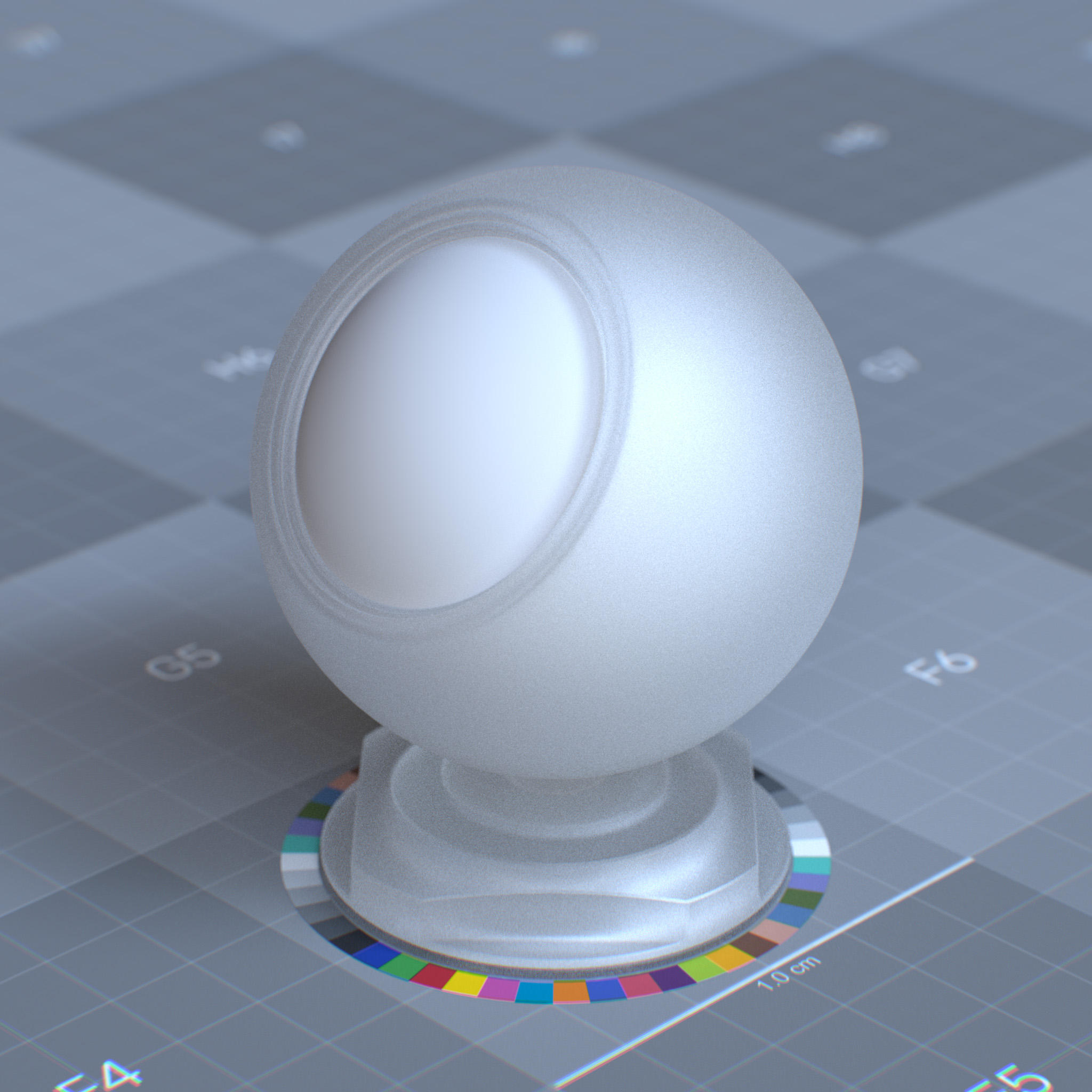
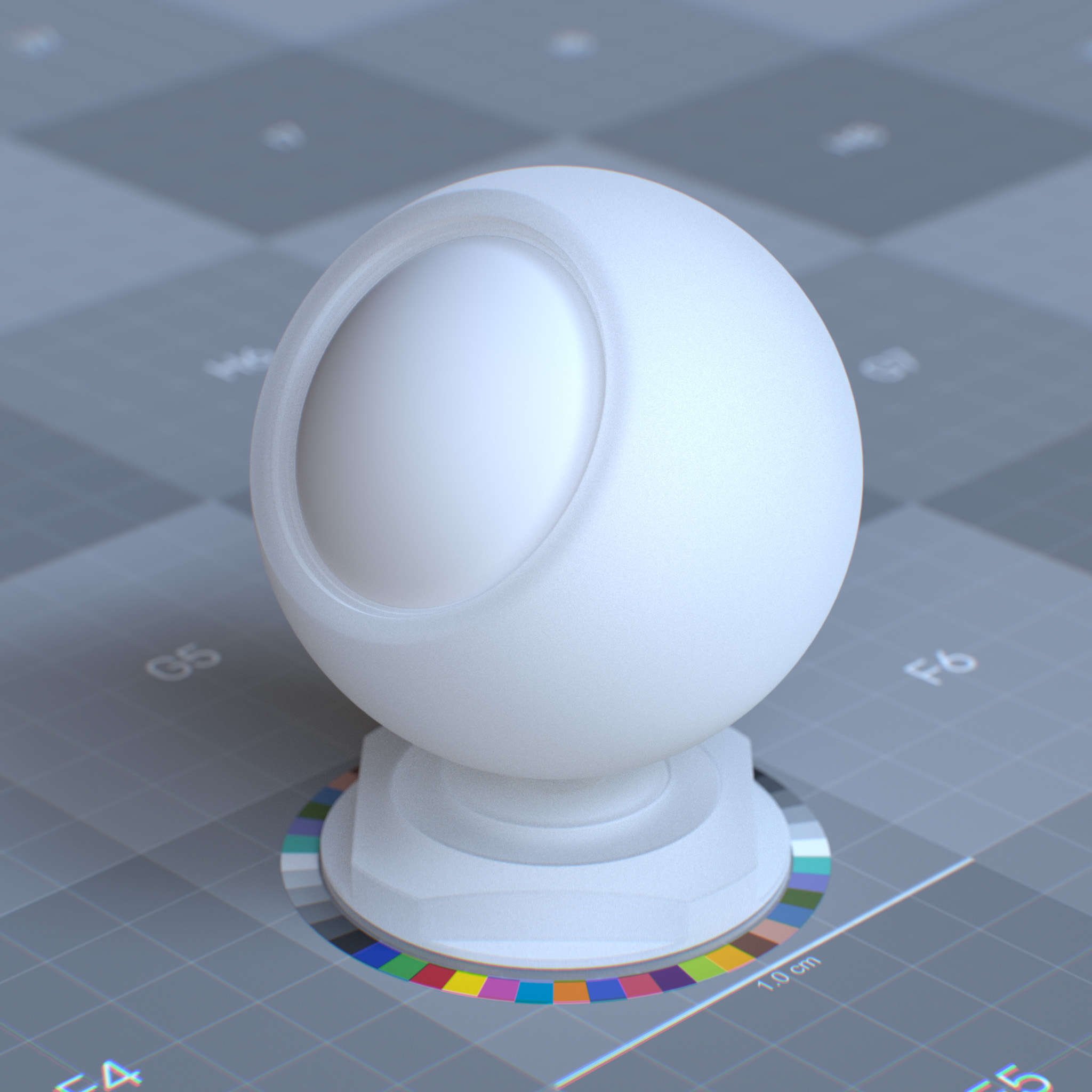
Roughness
This parameter sets the surface microfacet’s irregularities that cause light diffusion. At 0.0 simulates a perfect and smooth reflective surface, while increasing the value causes reflective highlights to diverge or appear blurred.
|
|
|
|
Roughness affects both specular reflection and specular transmission.
|
|
|
|
Tip
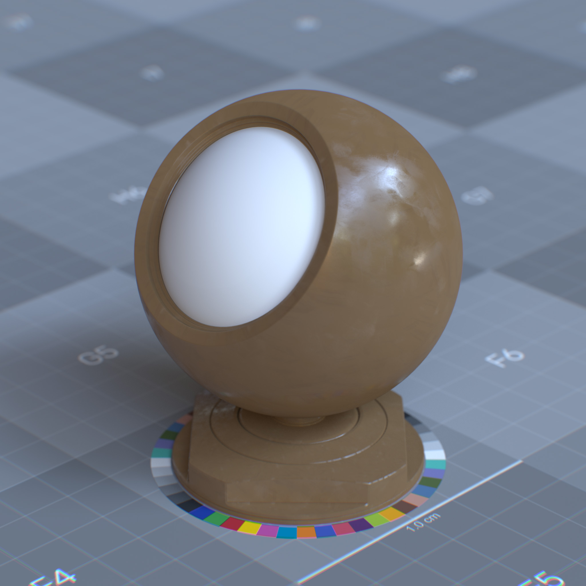
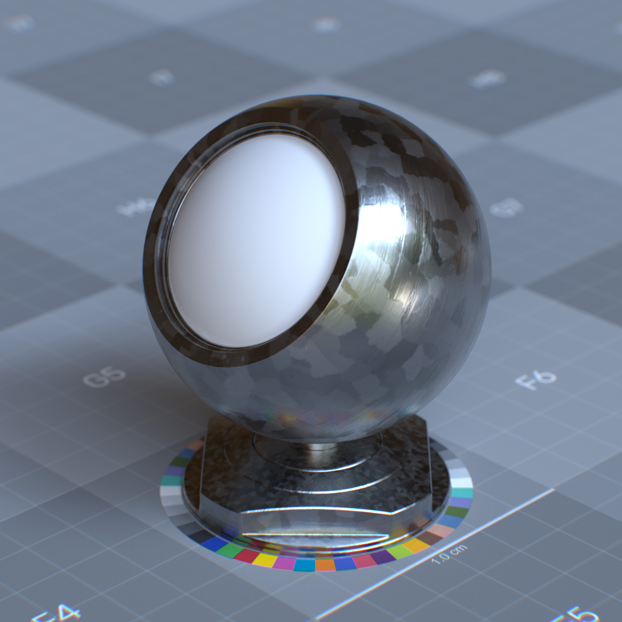
Roughness can create effects like torn surfaces, galvanized metal, or surfaces with fingerprints and smudges.
|
|
IOR Preset
This parameter presents a list of known IORs (index of refractions) for various materials, including glass, ice, diamond, skin. One can use custom IOR by setting this parameter to ior_custom and a value for the specular reflection’s IOR parameter.
IOR
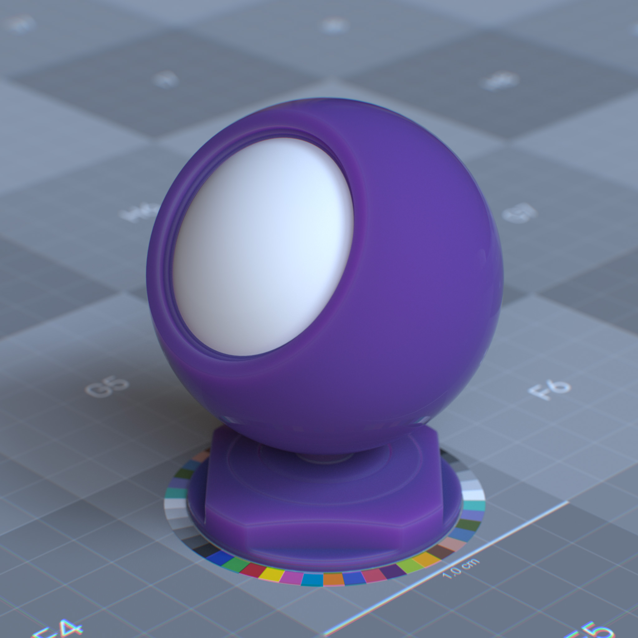
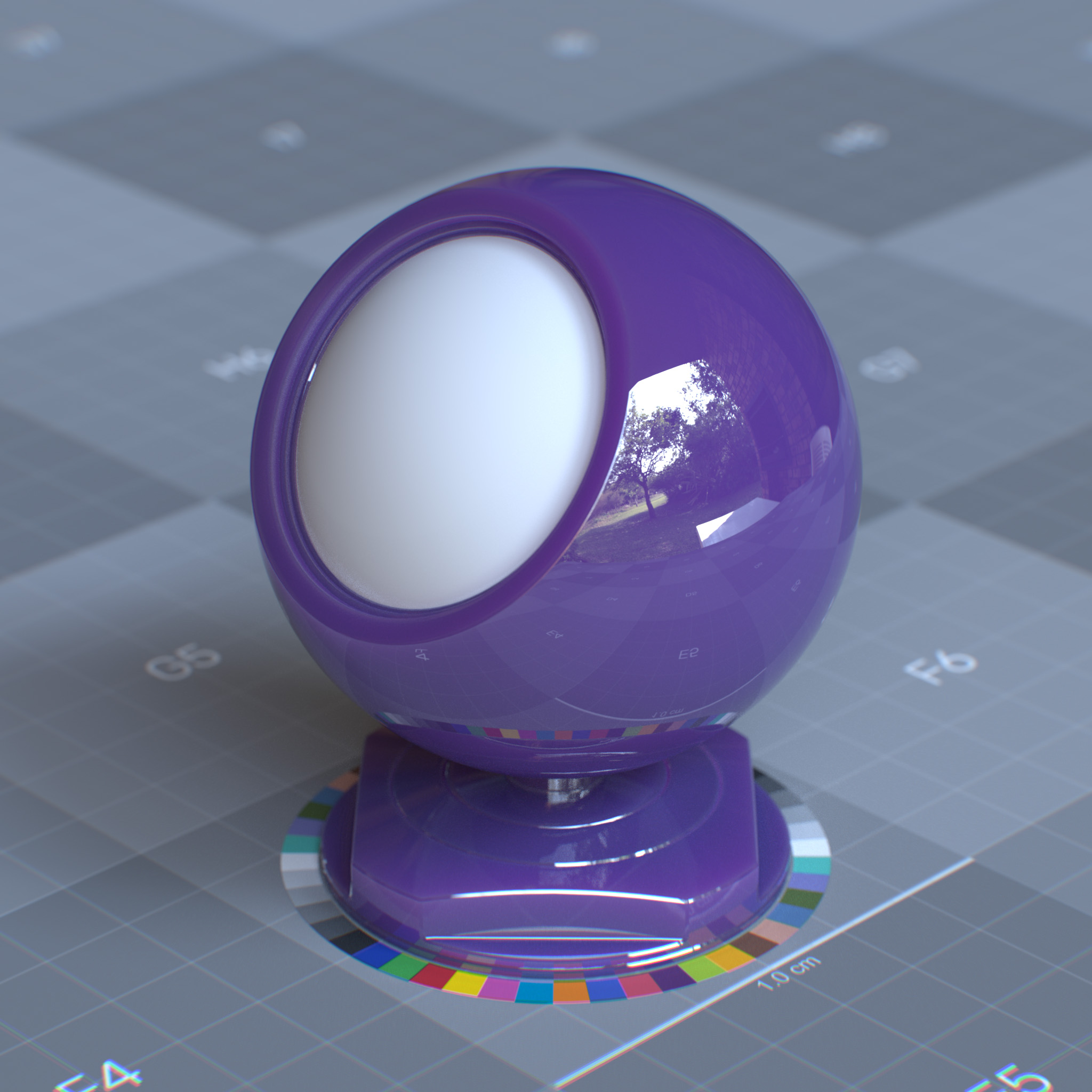
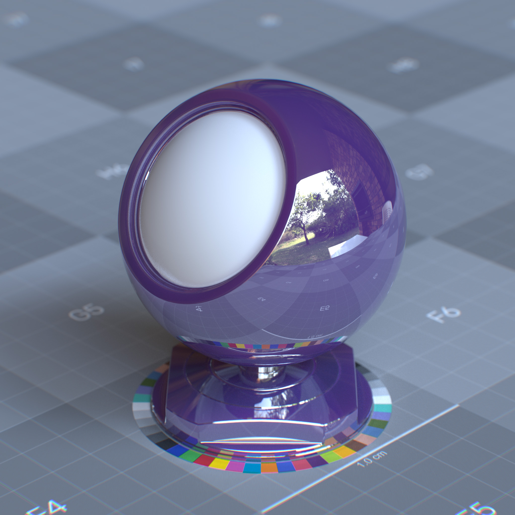
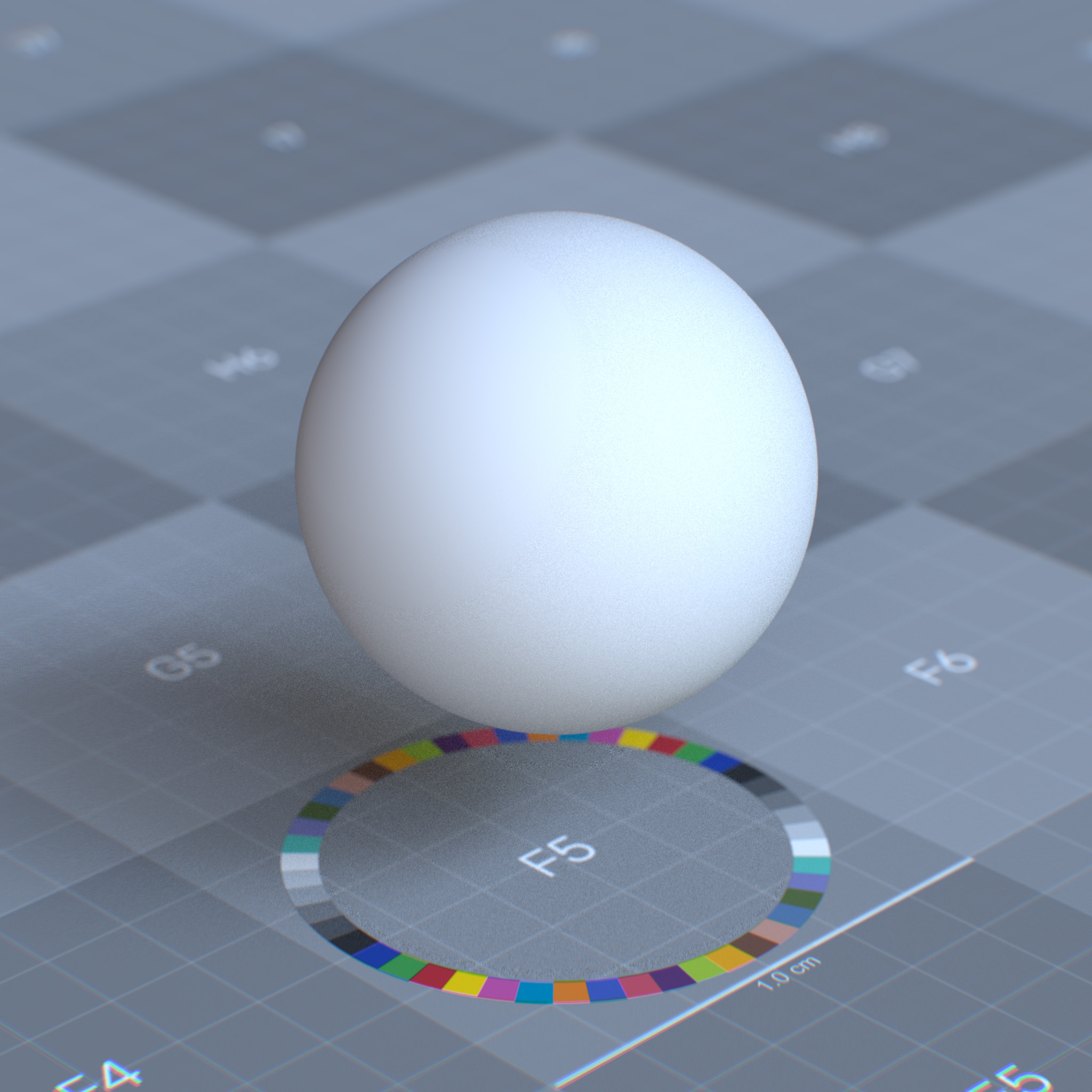
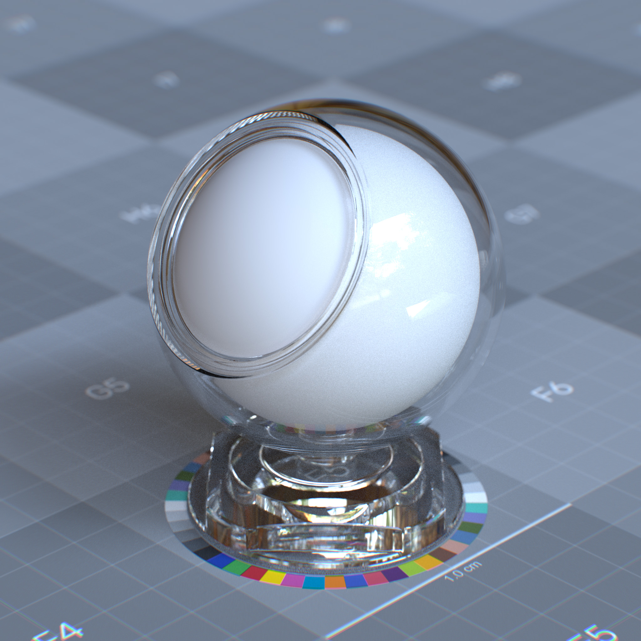
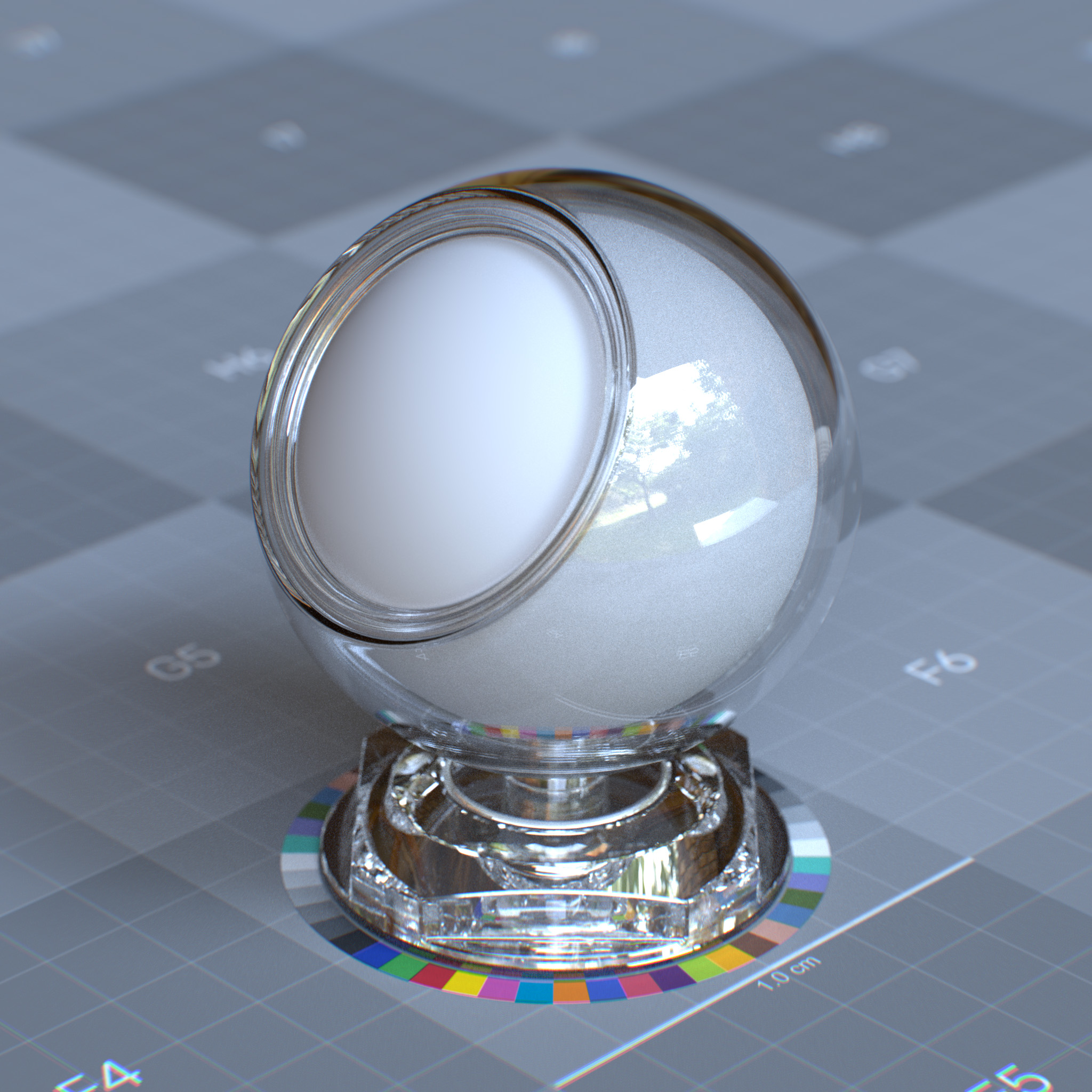
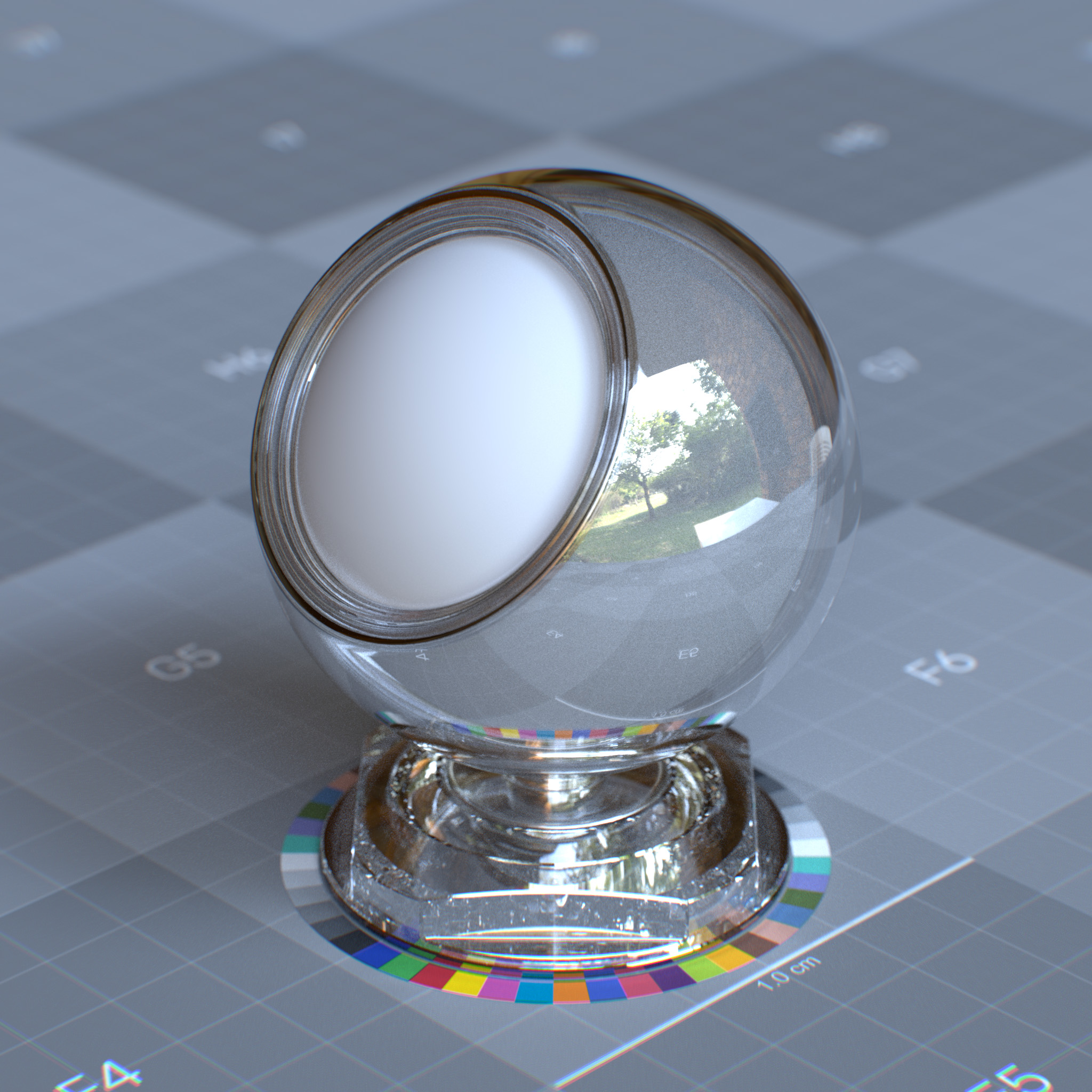
This parameter sets IOR (index of refraction), which affects surface Fresnel reflectivity. The IOR defines the ratio between reflection on the surface front, facing the viewer, and the surface edges, facing away the viewer.
At values above 1.0, the reflection appears stronger on the surface edges and weaker on the surface front. At values less than 1.0, the Fresnel is disabled, and the specular reflection appears as a uniform highlight over the surface.
Tip
At high values, the surface will look similar to a metallic surface. If a metallic look is desired, the metalness parameter is encouraged instead since the range [0, 1] can be easily mapped with an input texture.
|
|
|
IOR affects both the specular reflection and the specular transmission.
|
|
|
|
Anisotropy
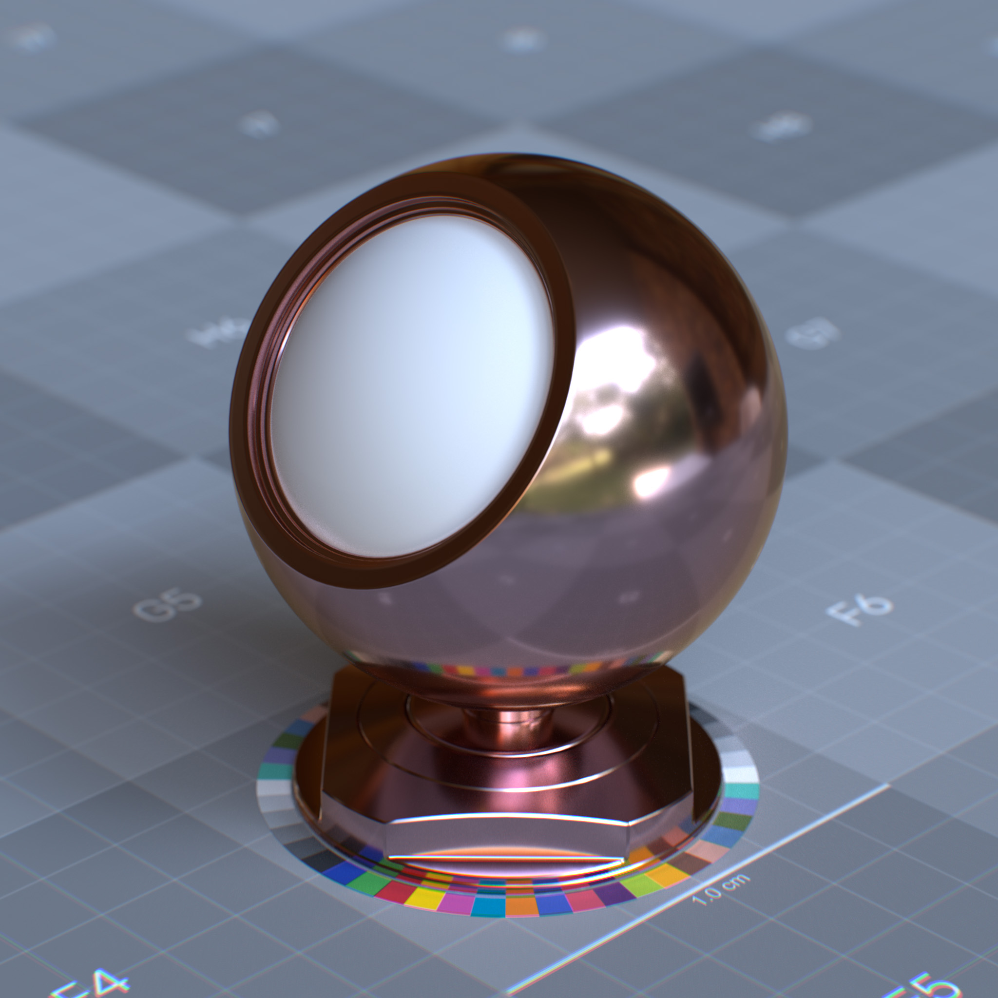
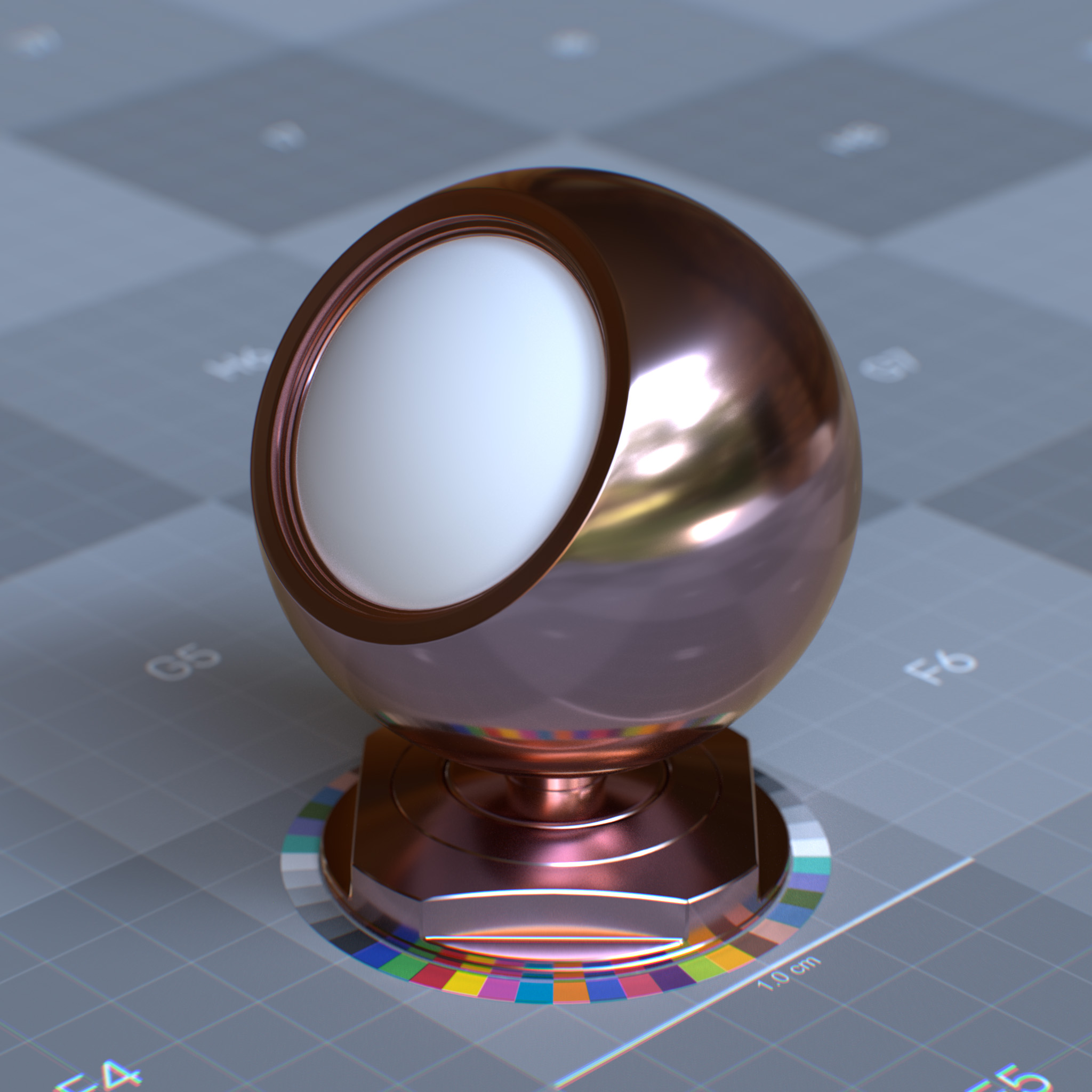
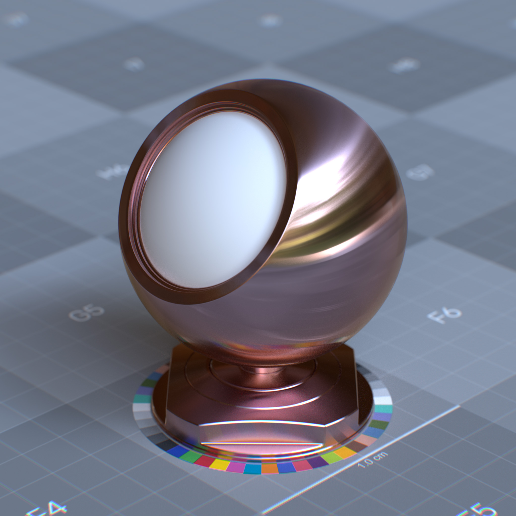
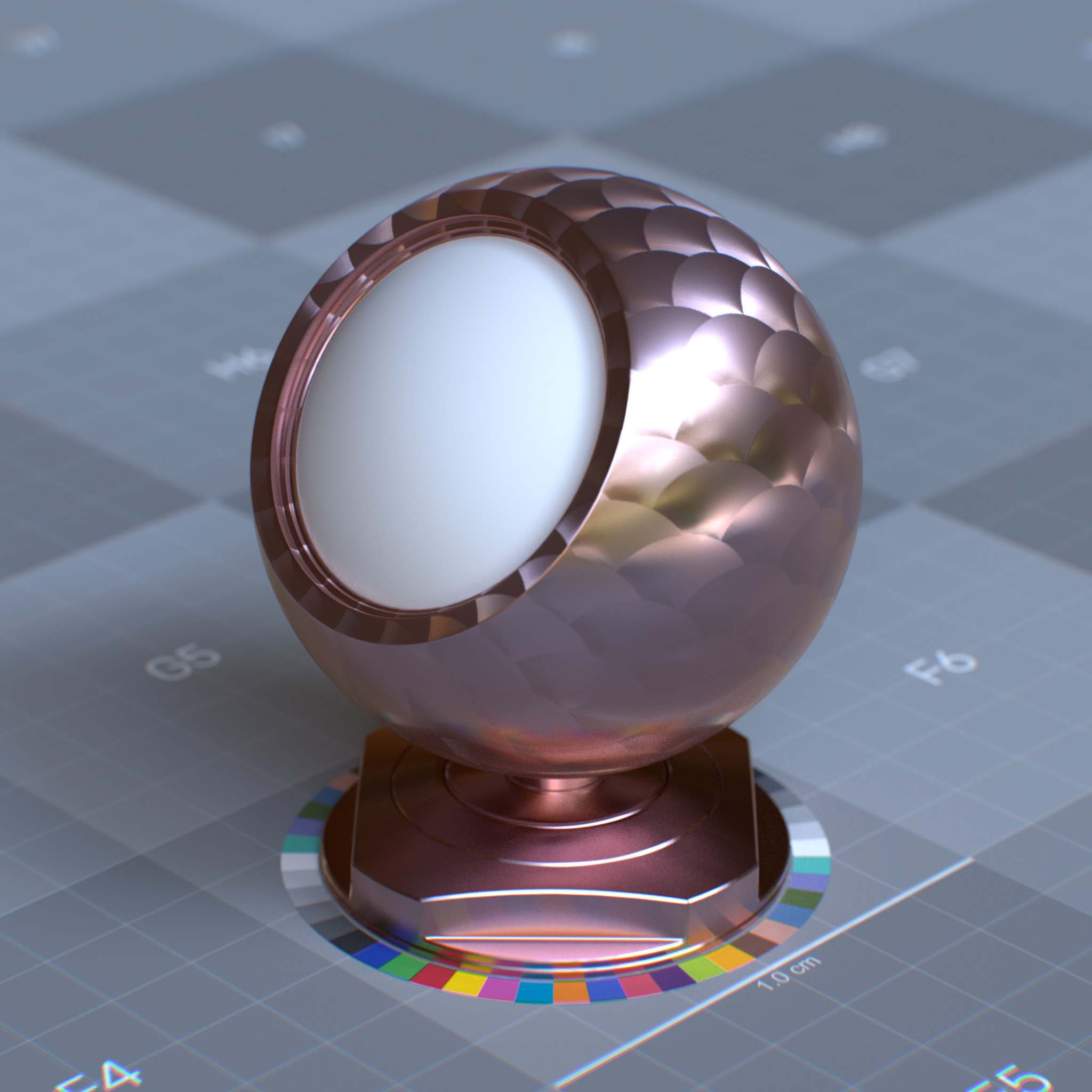
This parameter sets the specular reflection anisotropy. Reflectance changes based on the surface orientation are called anisotropic. If the reflectance is uniform in all directions and does not change based on the surface’s rotation or orientation, it is isotropic.
At values above 0.0, the surface transmits and reflects incoming light with a directional bias. Thus it appears rougher in a specific direction.
|
|
|
|
Rotation (radians)
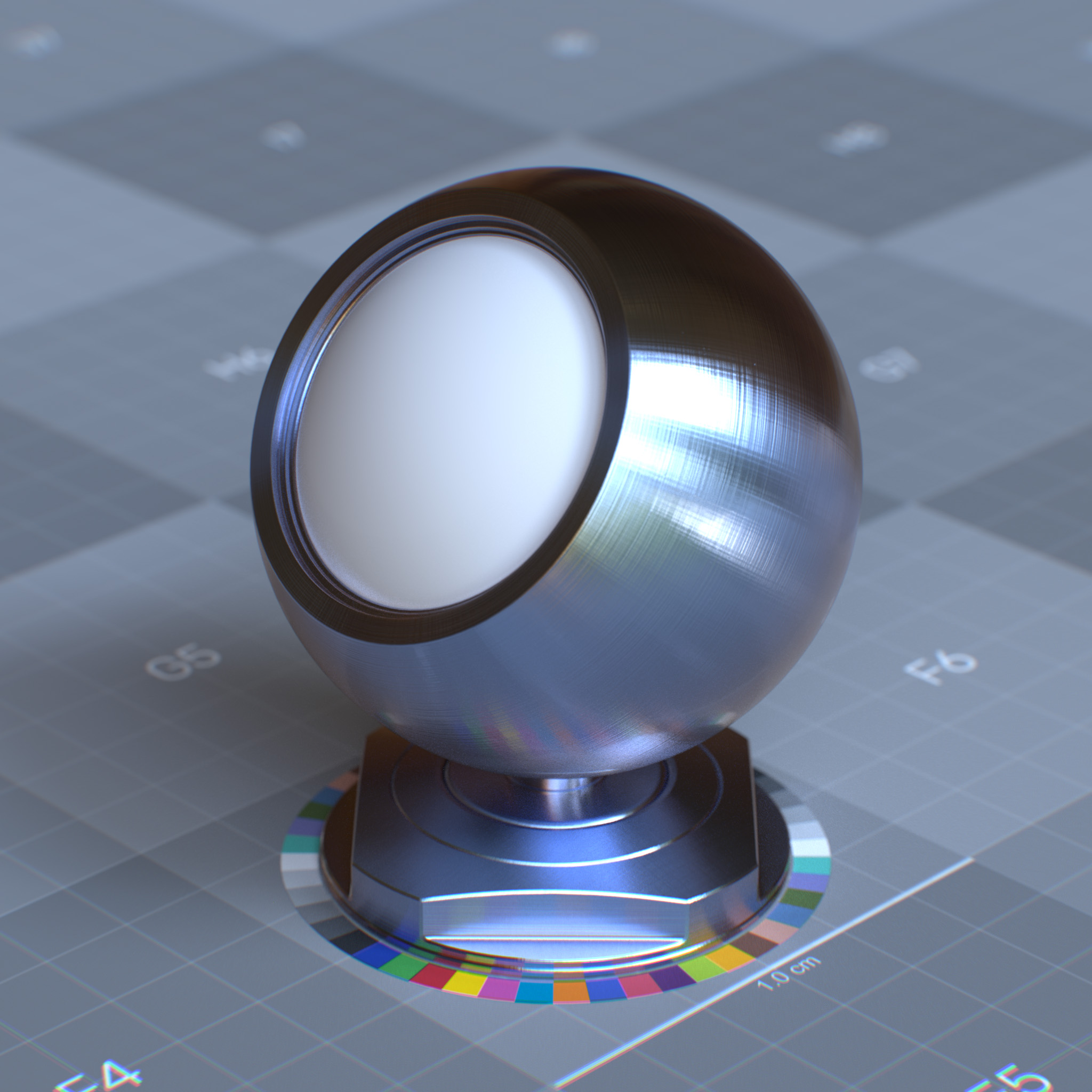
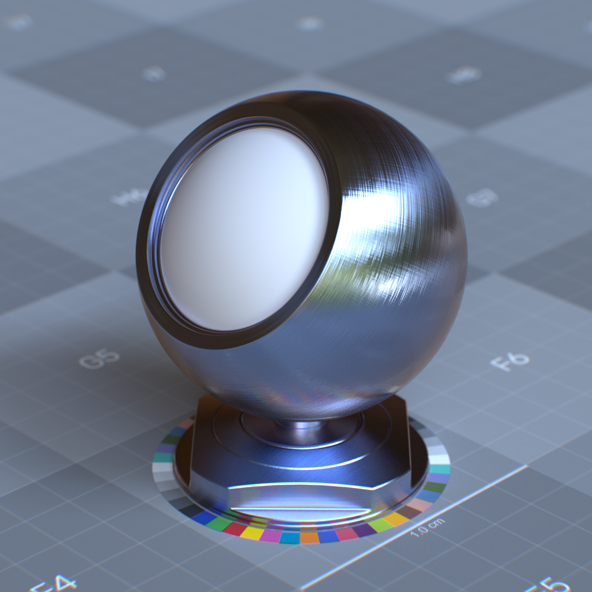
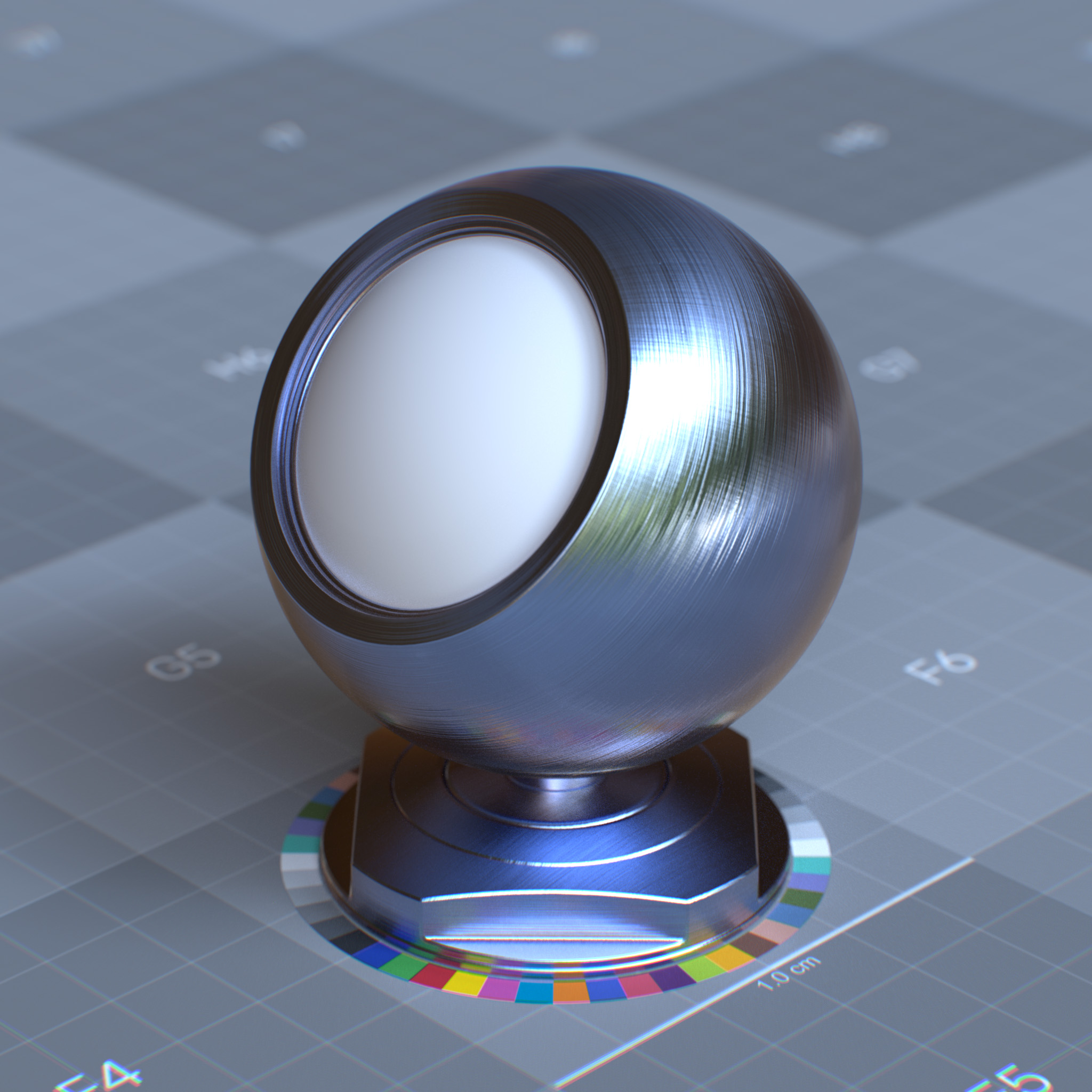
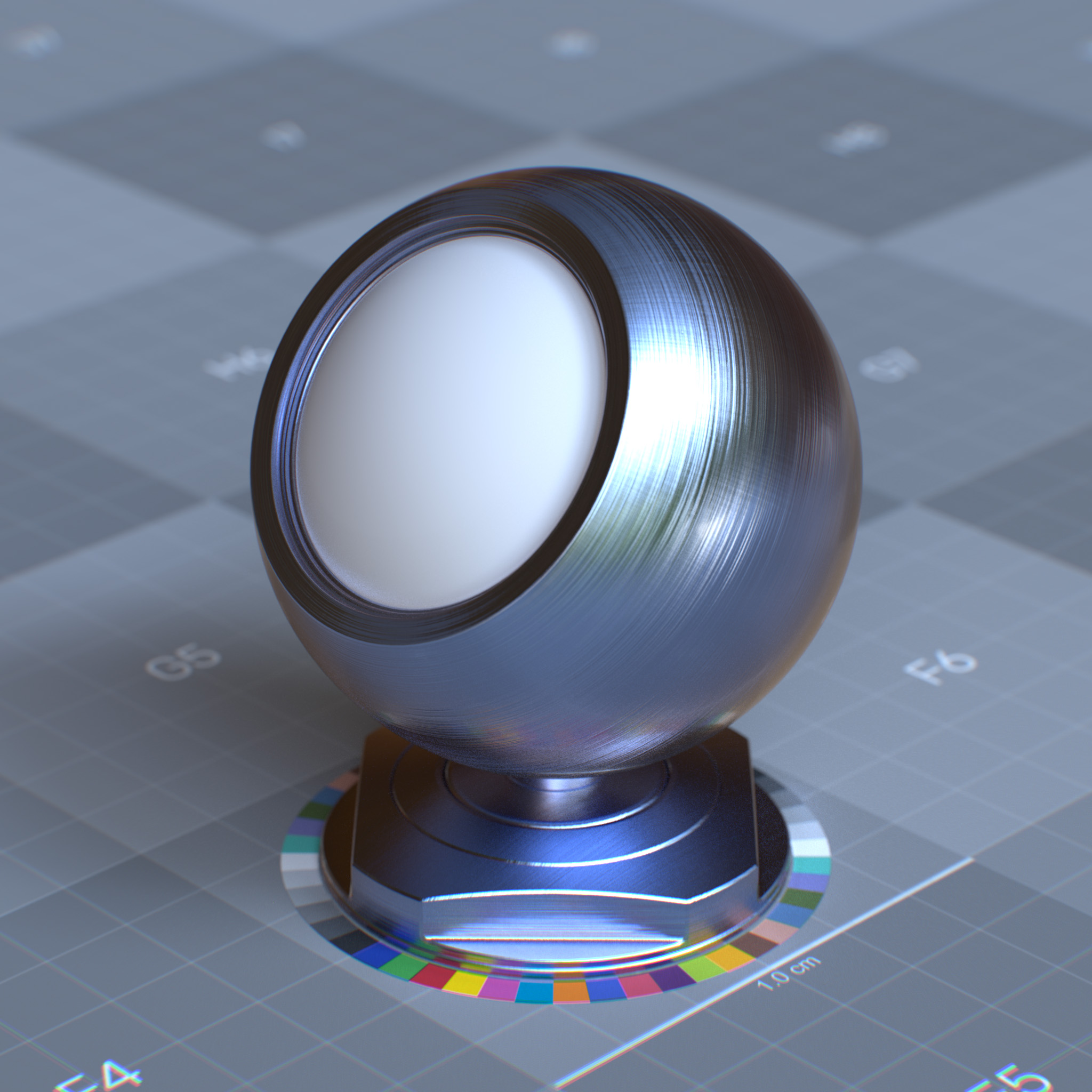
This parameter sets the orientation of the anisotropic effect in radians. At 1.0, the anisotropic effect is rotated by 180 degrees. For brushed metallic surfaces, the anisotropic effect should stretch out in a direction perpendicular to the brushing direction.
|
|
|
|
Transmission
Transmission defines how light passes through a material. It controls transparency and refraction effects in glass, liquids, thin plastics, and other translucent materials. The transmission properties determine light absorption, color filtering, and how rays bend when entering and exiting the material.
Parameters
Display Name |
Name |
Type |
Default |
|---|---|---|---|
enable_specular_transmission |
bool |
false |
|
specular_transmission_weight |
float |
0.0 |
|
specular_transmission_color |
color |
1.0, 1.0, 1.0 |
|
specular_transmission_scattering_depth |
float |
0.0 |
|
specular_transmission_scattering_color |
color |
0.0, 0.0, 0.0 |
|
specular_transmission_scatter_anisotropy |
float |
0.0 |
|
specular_transmission_dispersion_abbe |
float |
0.0 |
This layer models a GGX microfacet BTDF within a homogeneous medium interior to the object, under the specular reflection layer. It shares a few key parameters with the Specular reflection layer, including Roughness, IOR, Anisotropy, and Anisotropy Rotation.
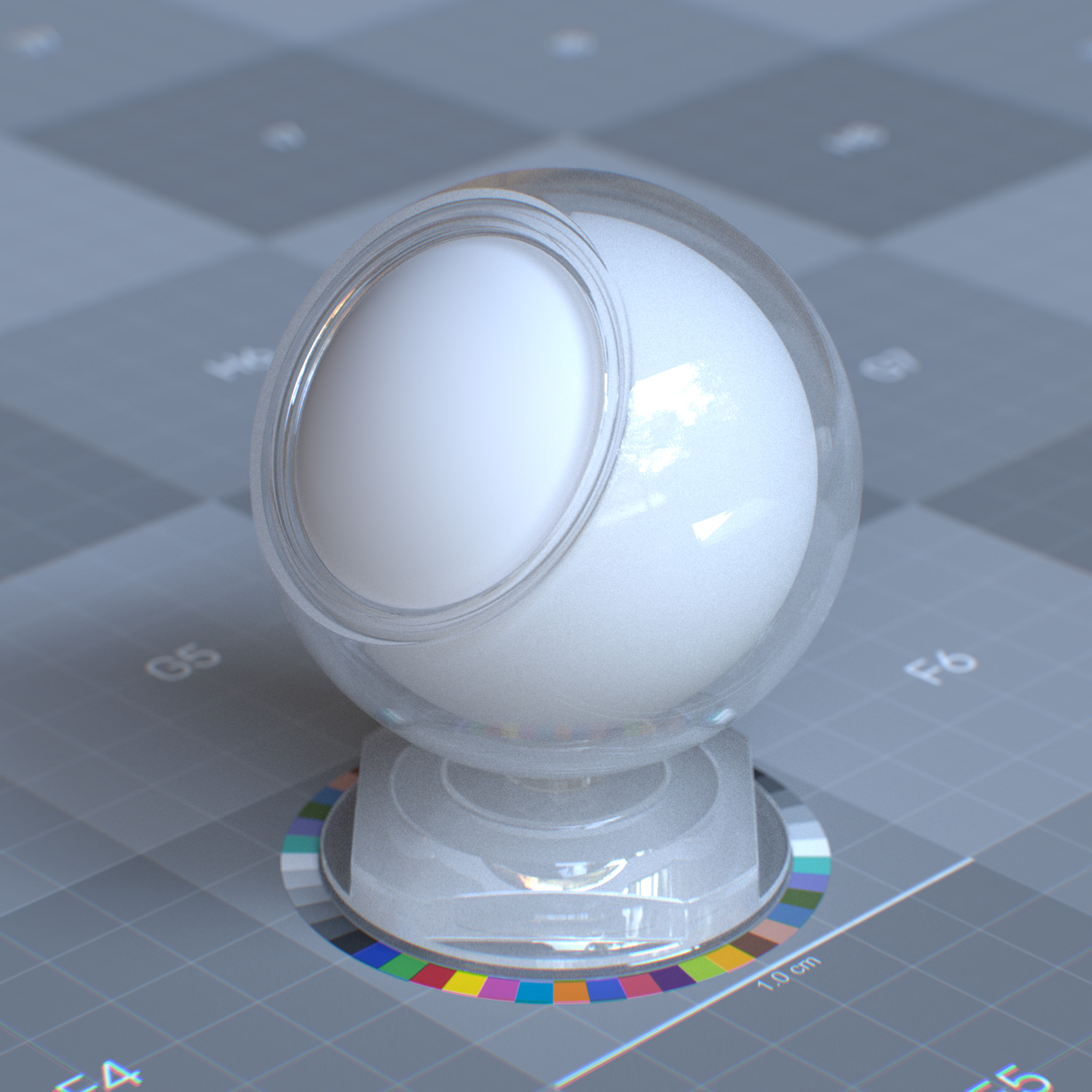
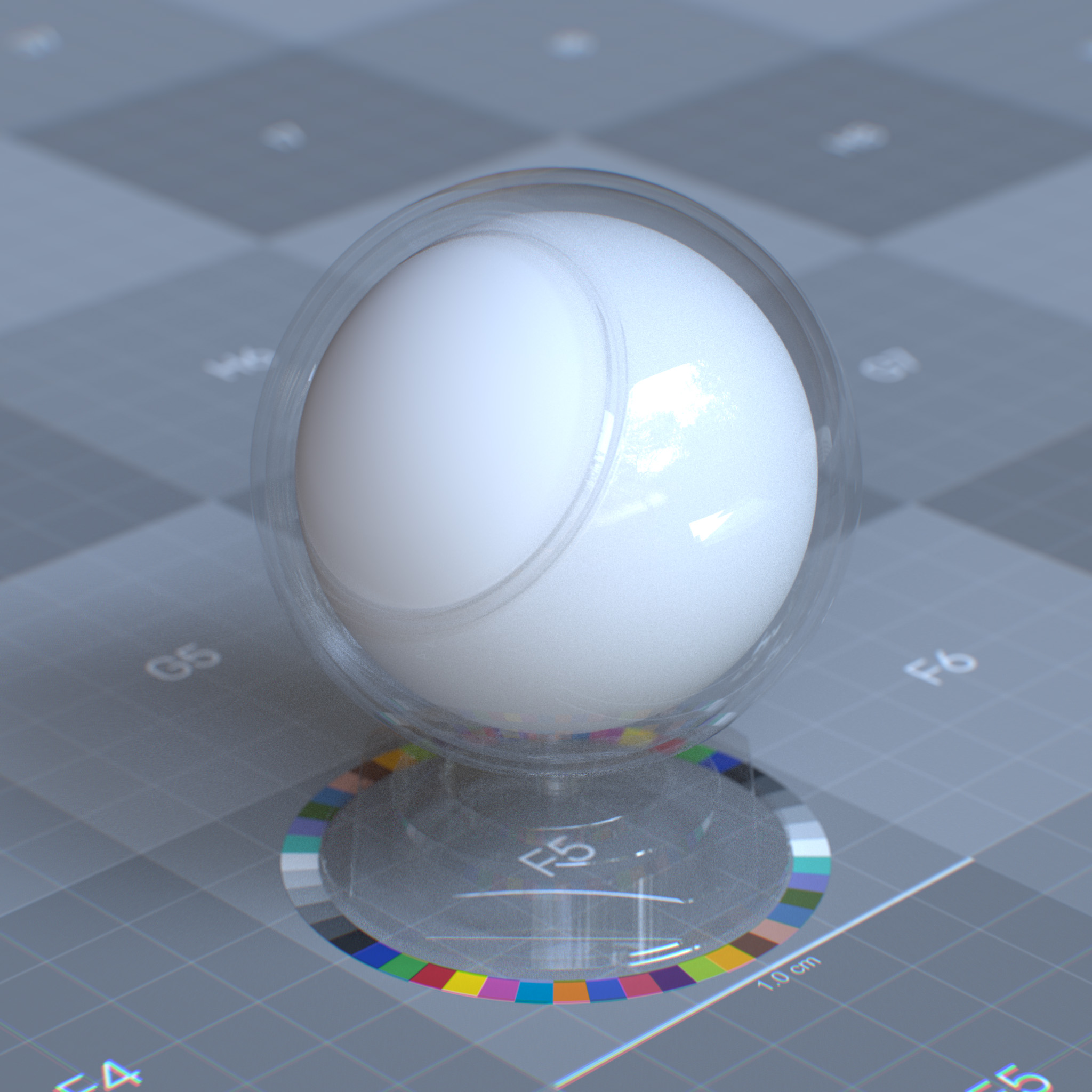
If thin-walled enabled, the surface appears double-sided, represented as an infinitely thin shell. Upon specular transmission, the incoming light is not refracted to the opposite side. The refraction index sets to the surrounding medium.
If thin-walled disabled, the surface is considered to be a boundary of a finite-sized solid object. And according to the specular reflection layer, the incoming light refracts when entering and leaving the object.
|
|
Note
Specular Transmission vs. Geometry Opacity
Specular transmission controls the surface transparency, while geometry opacity controls the surface visibility. One can use the specular transmission to create a glass surface and then use the opacity to cut the surface.
Note
In the RTX – Interactive (Path Tracing) mode, if refraction appears black, one may need to increase Max Bounces Specular/Transmission and Max Bounces in the render settings panel.
Please see RTX Interactive (Path Tracing) mode render settings for more information.
Enable Specular Transmission
Enables specular transmission layer
Weight
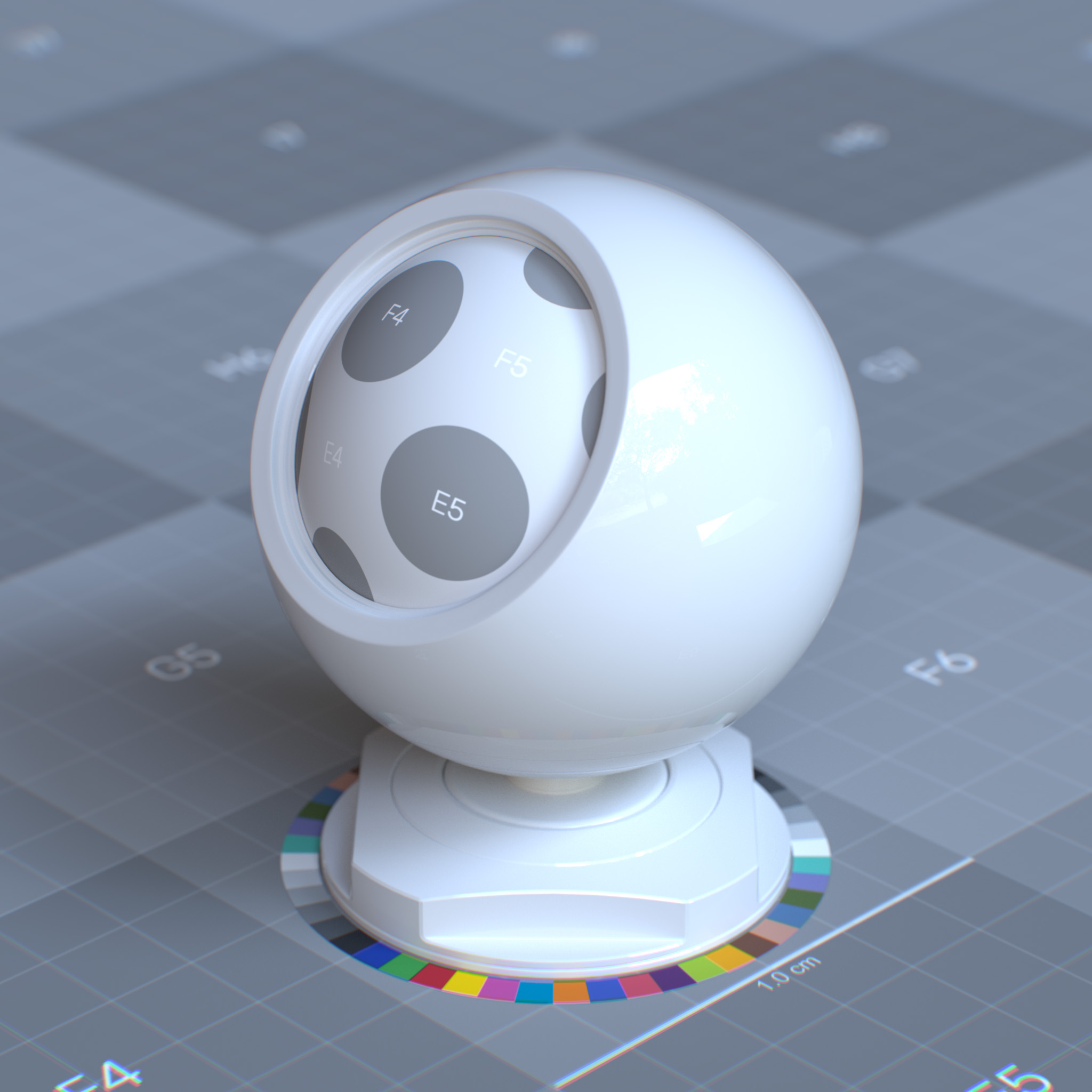
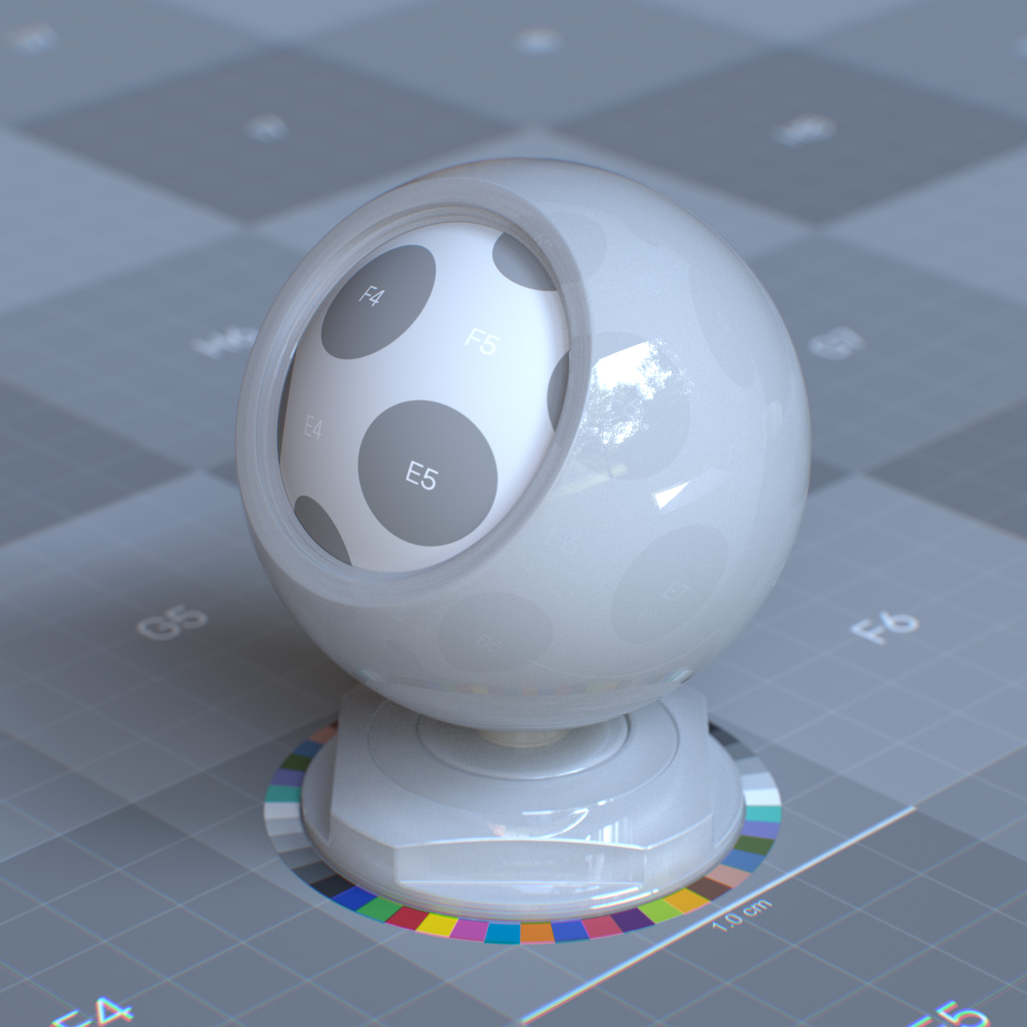
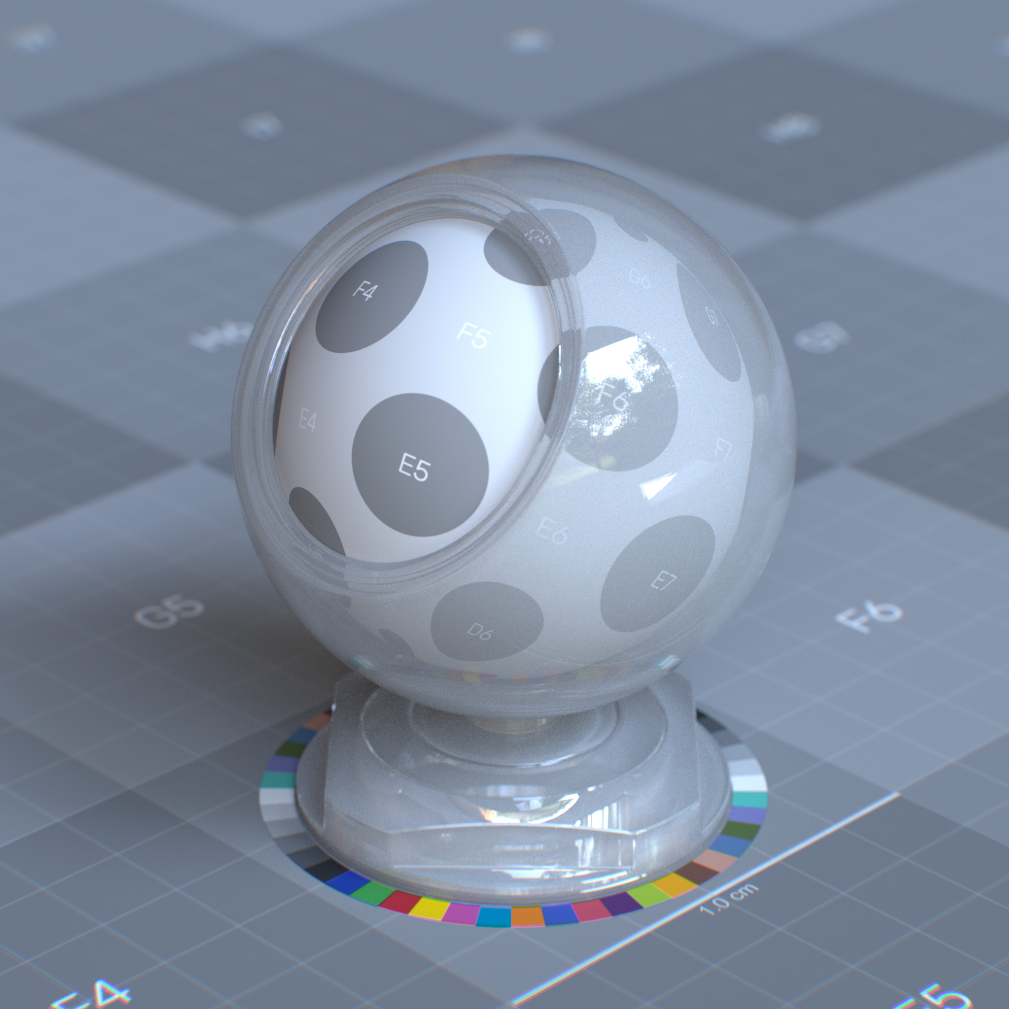
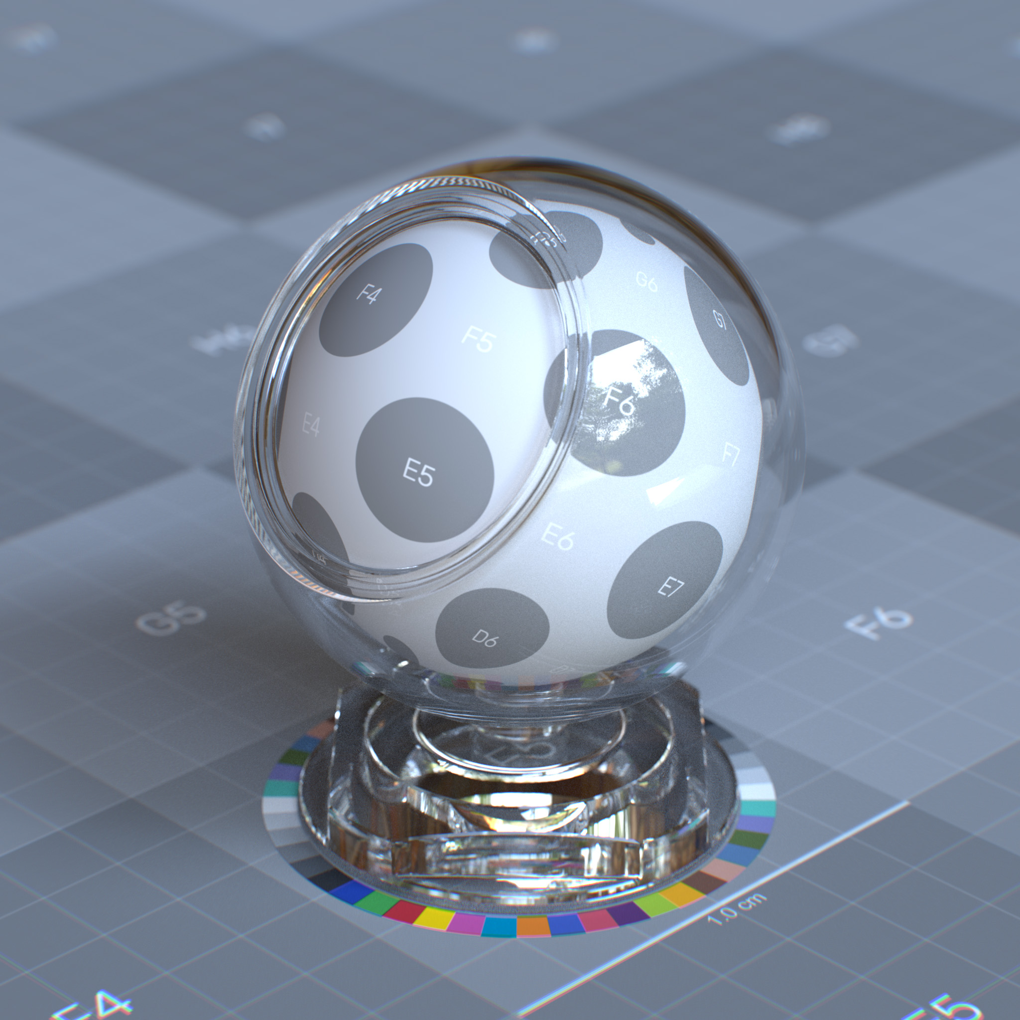
This parameter sets the amount of light to pass and scatter through the surface. At 0.0, the surface is completely opaque, while at 1.0, the surface is fully transparent.
|
|
|
|
Color
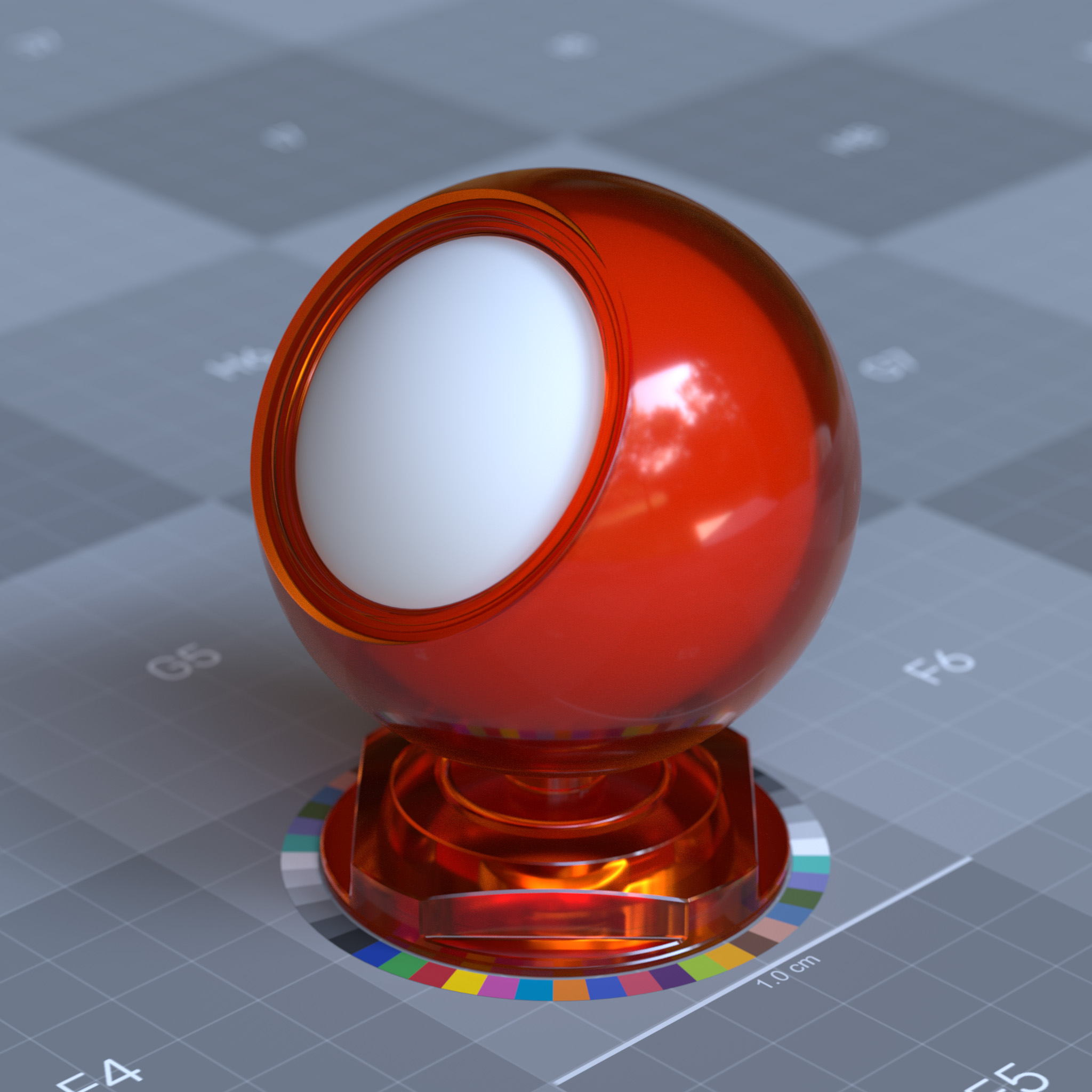
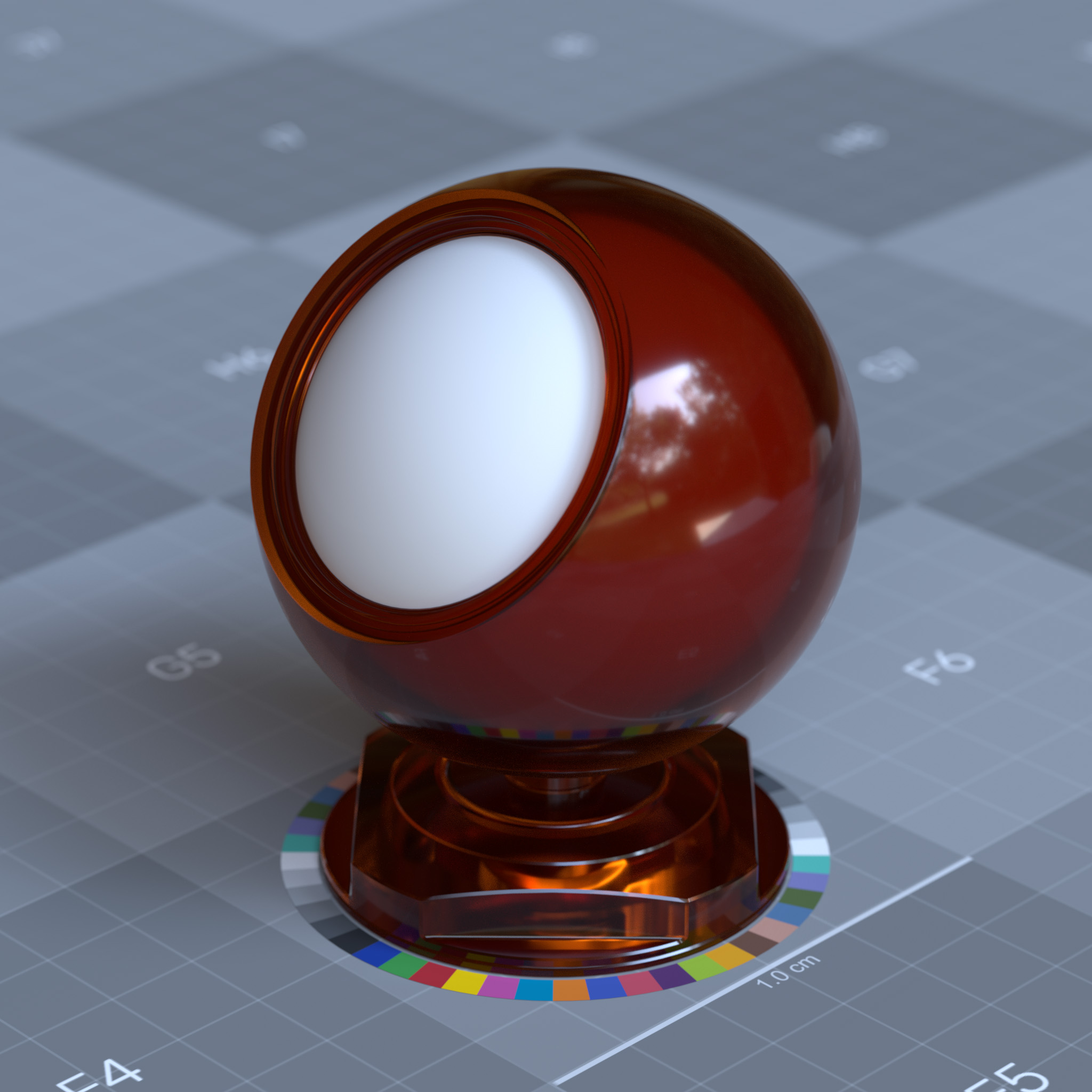
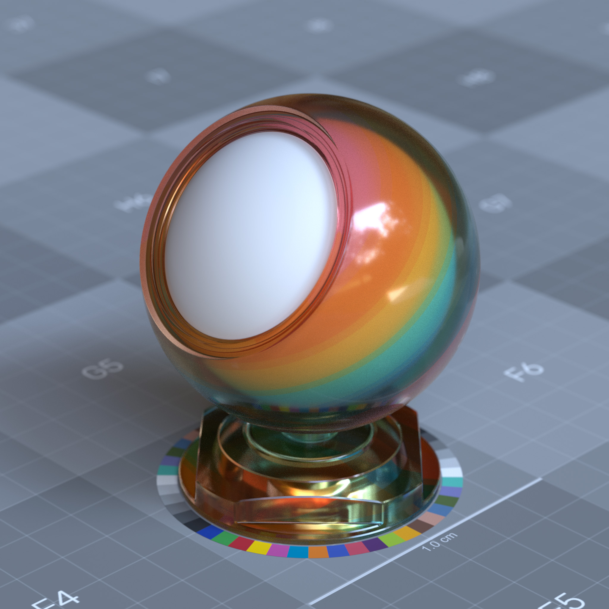
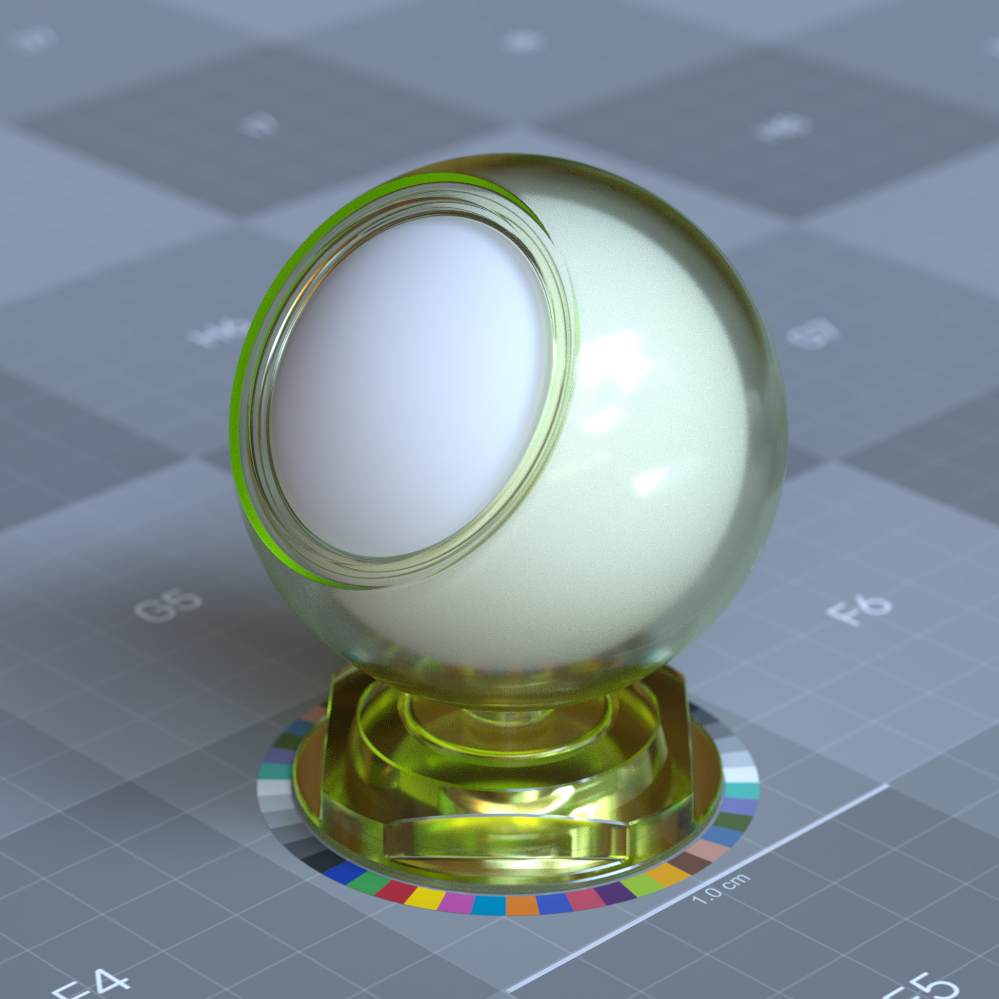
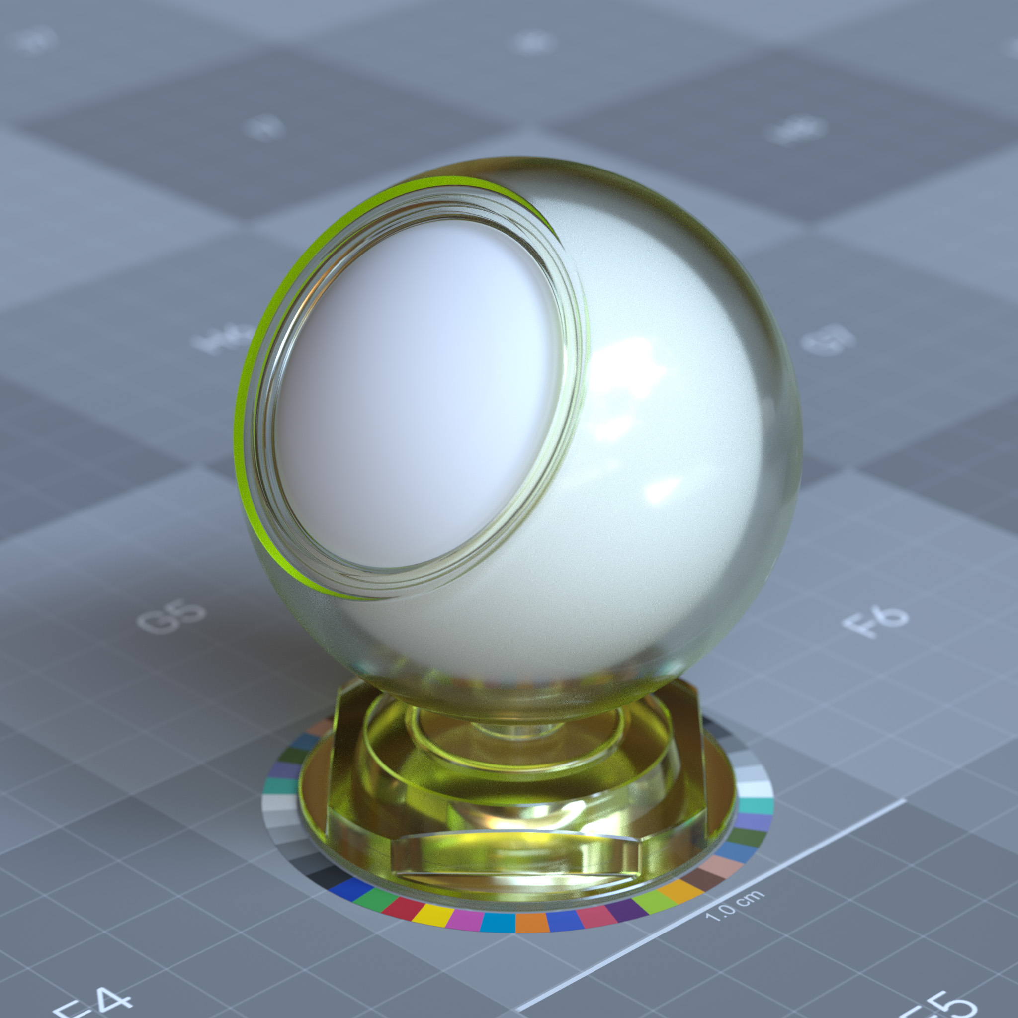
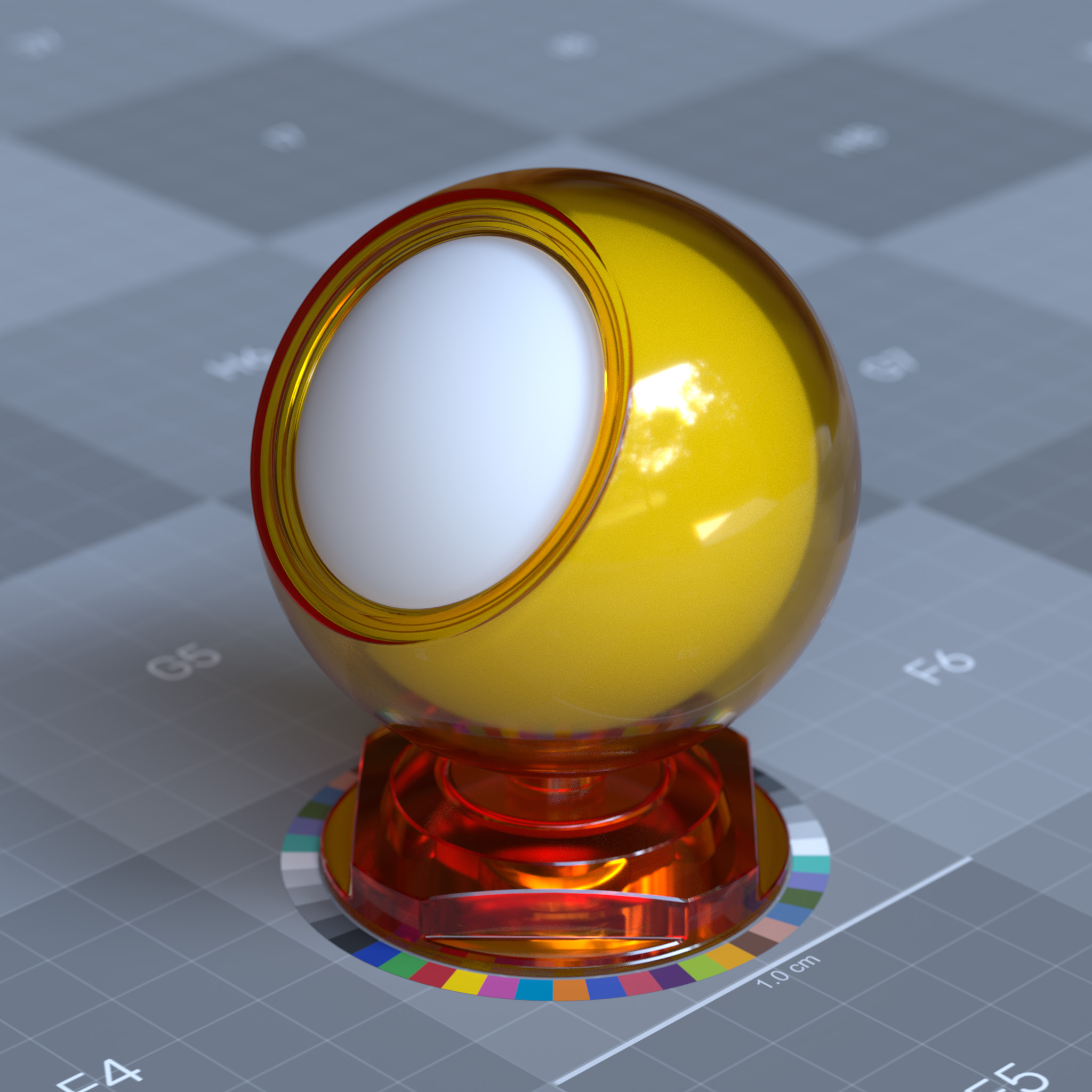
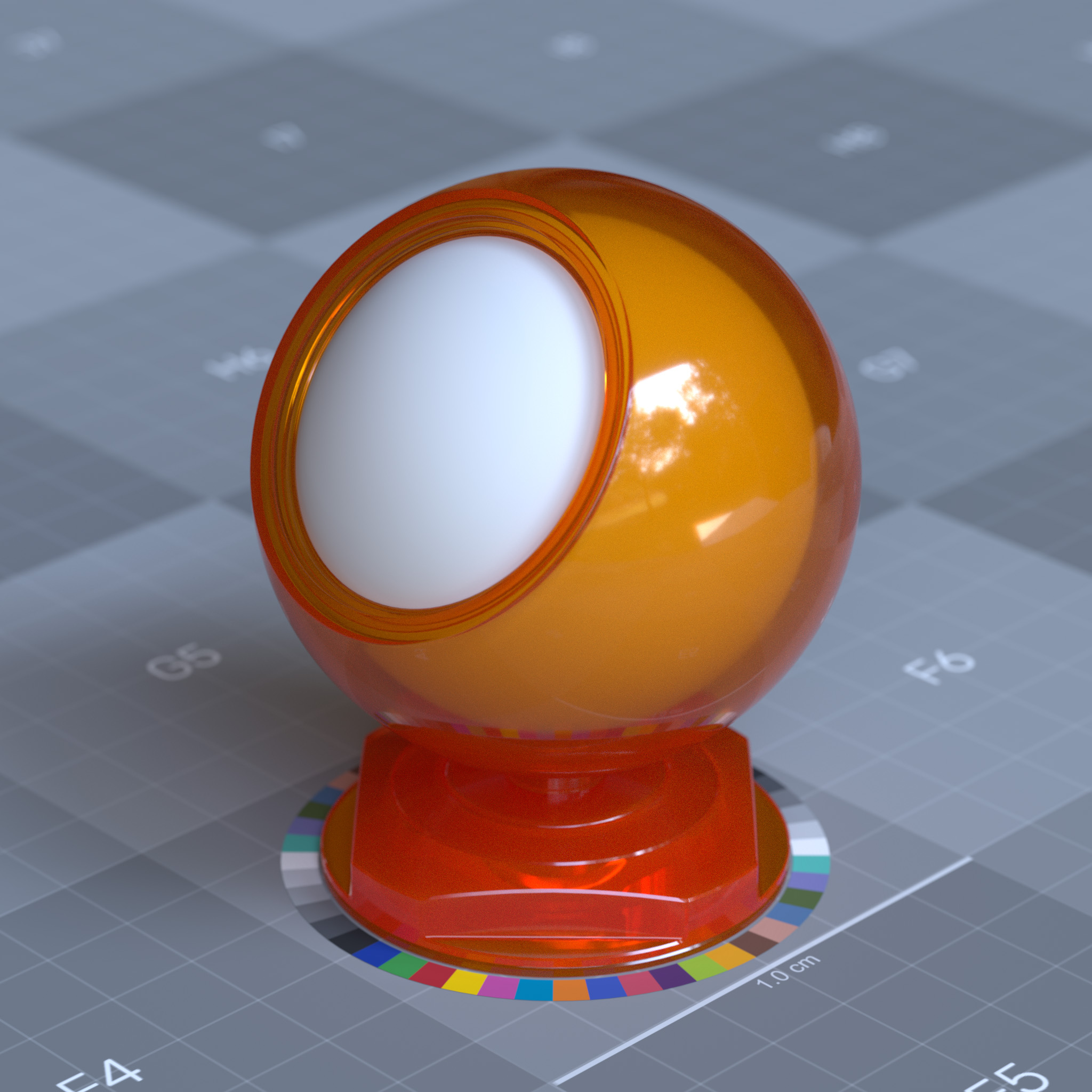
This parameter sets the transmission color, which affects the travel of refracted rays in the volume using Beer’s law. Therefore red colored glass gets a deeper red as refracted rays travel deeper in the volume. A transmission color close to black makes the interior of the volume very dense. A darker transmission color can be used to render deep-ocean water, orange juice, and similar materials. Color and Depth’s positive values are used together to set the extinction coefficient (sigma_t) of the interior volume to the object.
Tip
For a realistic result, specular transmission color should not be set to saturated colors, i.e., pure red (1.0, 0.0, 0.0).
|
|
|
Depth
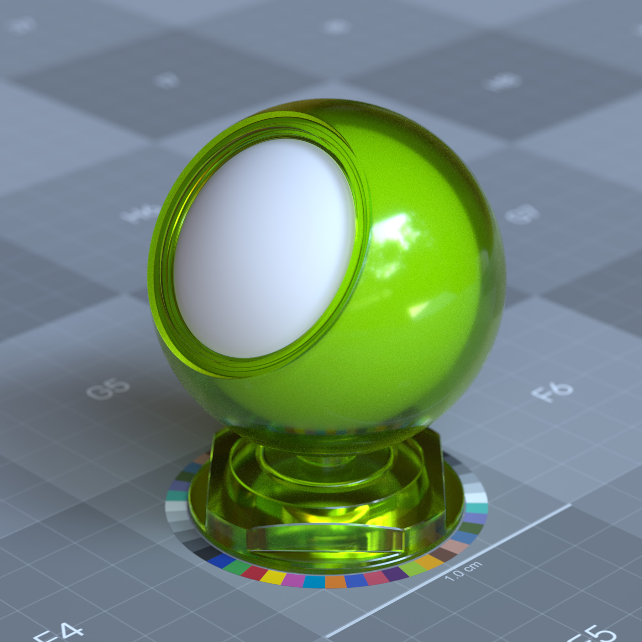
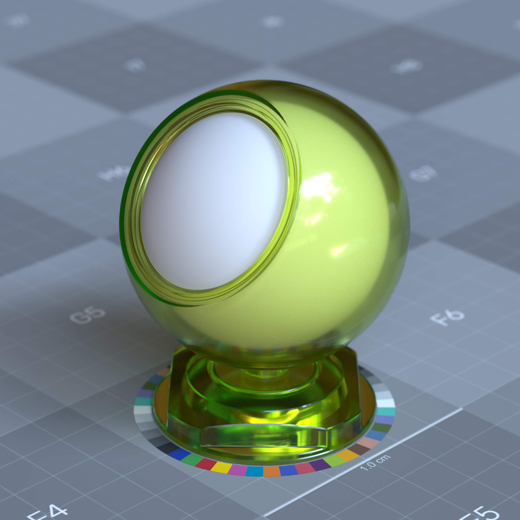
This parameter sets the distance traveled by refracted white rays before their colors turned into the transmission color by Beer’s law. At 0.0, the interior medium to the object is null, and transmission color tints the material’s refraction. Decreasing the depth increases the volume absorption and scattering, which makes the volume more opaque.
The effect of depth depends on the absolute size of the objects, and hence depth is a scene scale-dependent parameter.
Tip
For a realistic result, one should model to a real-world scale and set the depth to 1.0.
|
|
|
|
Scatter
This parameter sets the scattering coefficient (sigma_s) of the interior medium to the object. The scattering color describes how much “refracted rays” are scattered while traveling inside the medium. The light’s red, green, and blue components are scattered by different amounts when the scattering color sets to a non-grey hue.
Ice, opalescent glass, and honey are a few examples of materials with a high scattering coefficient.
|
|
Scatter Anisotropy
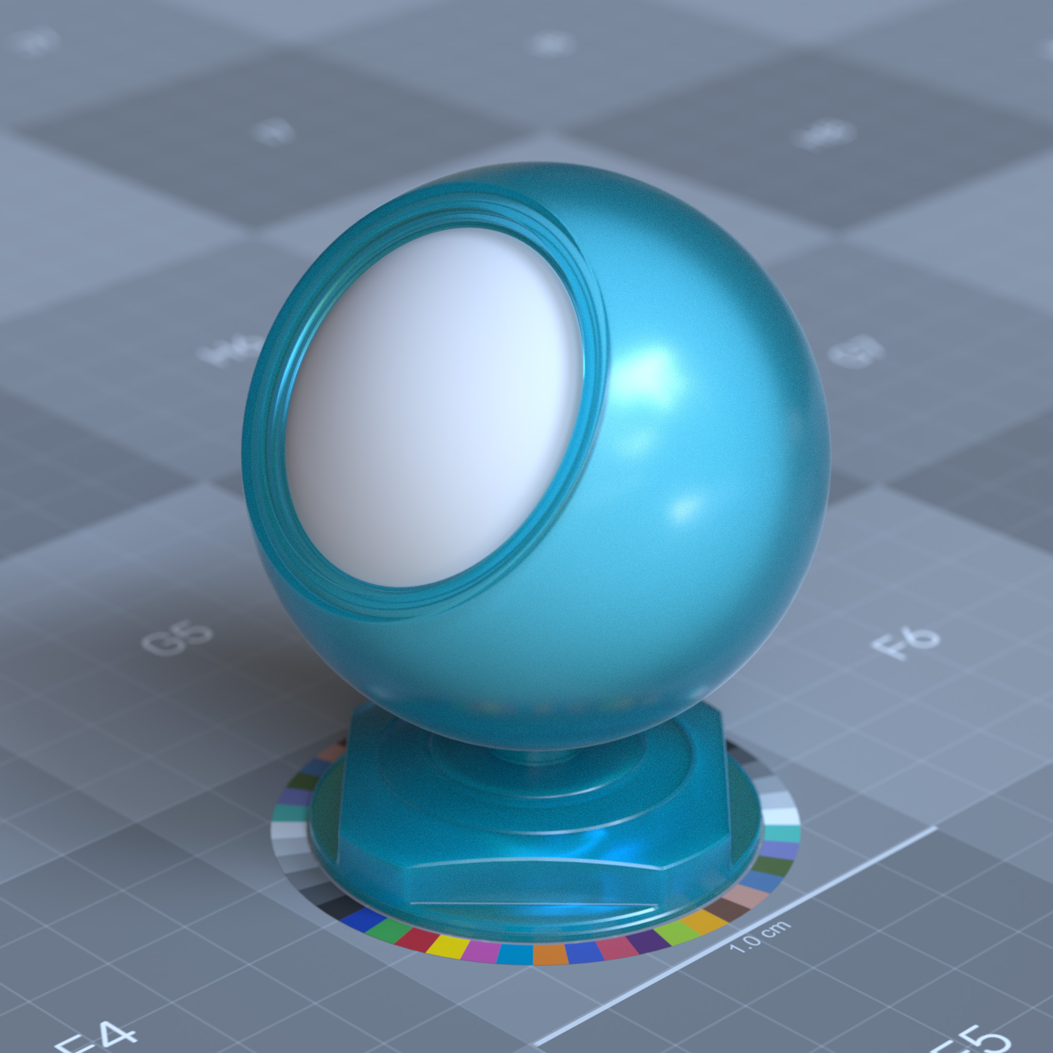
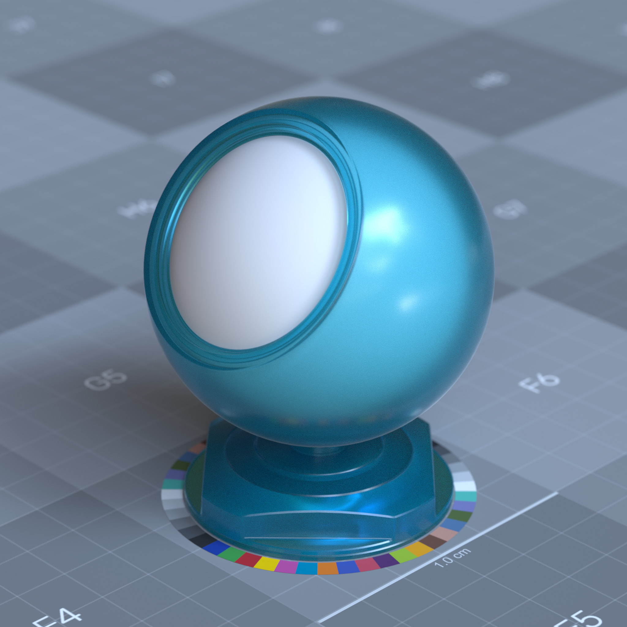
This parameter sets the scattering directionality or anisotropy of the “Henyey-Greenstein” phase function of the interior medium to the object. At 0.0, scattering sets to isotropic, and light is scattered uniformly in all directions. Values above 0.0 biases the scattering effect forward in the direction of the light, while values below 0.0 biases the scattering effect backward in the opposite direction of the light.
|
|

|
Dispersion Abbe
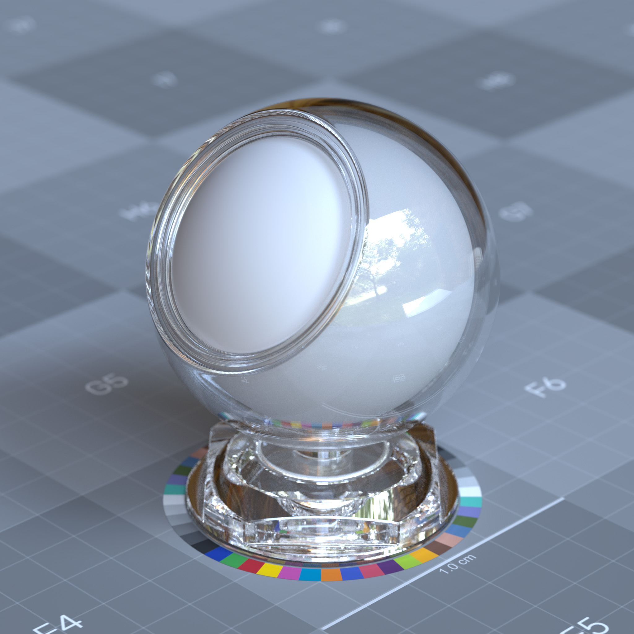
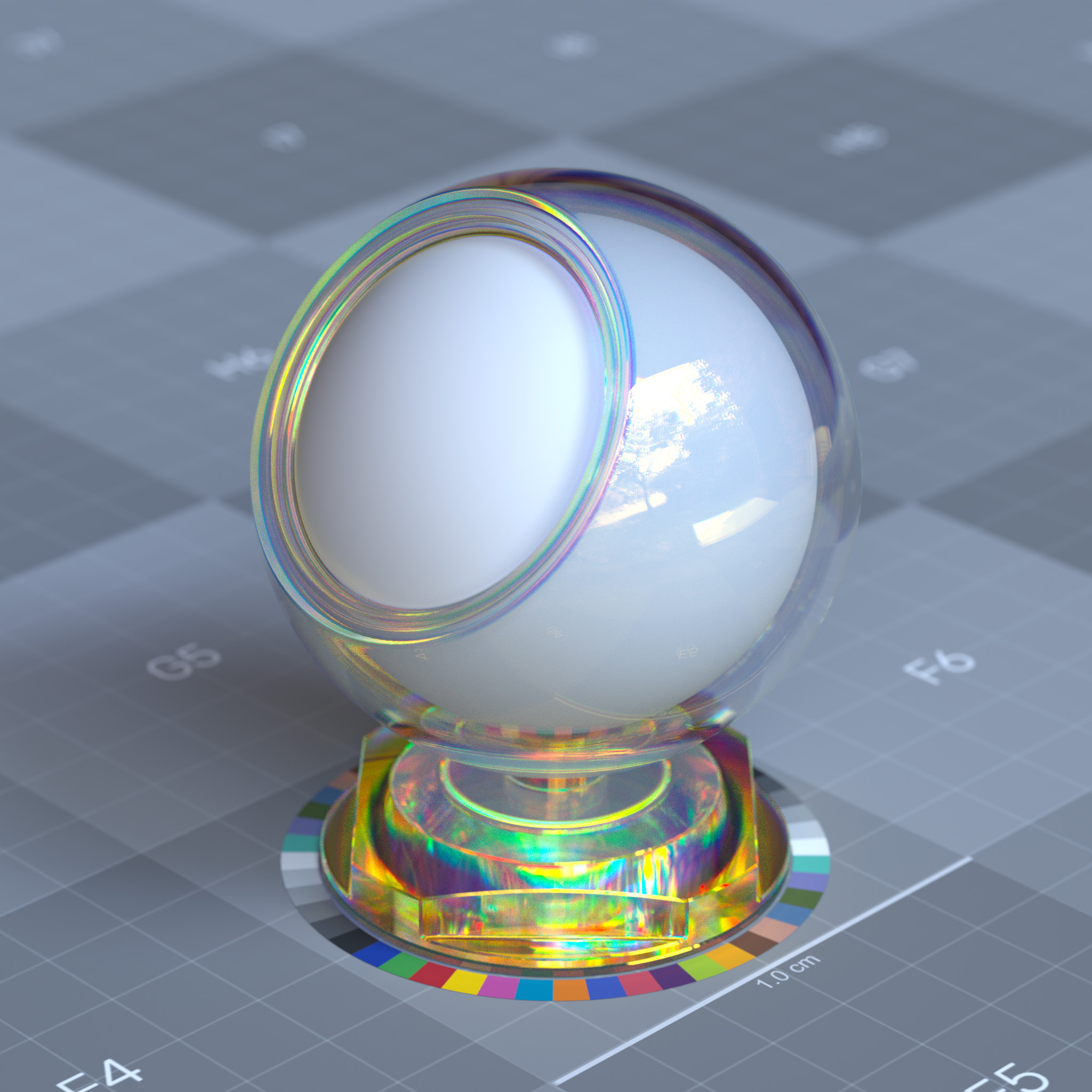
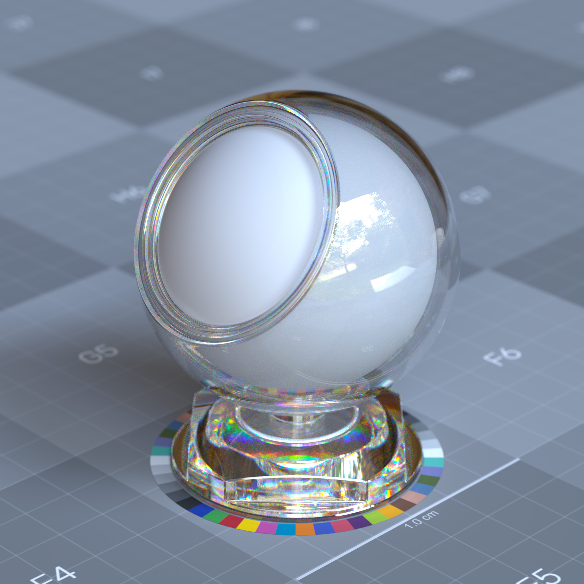
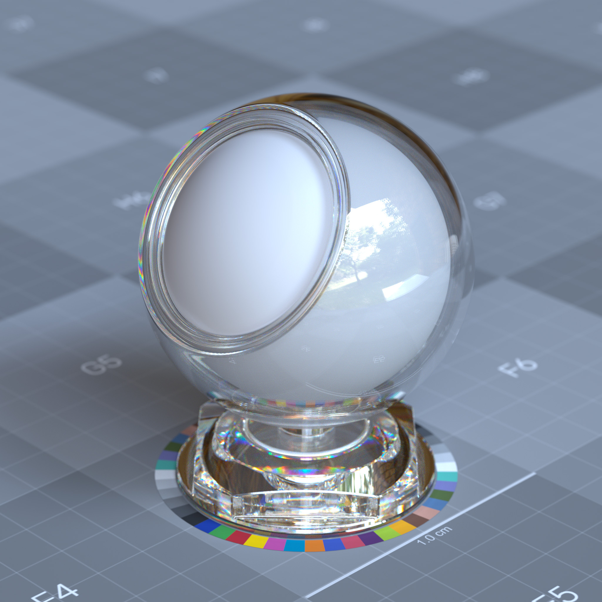
This parameter sets how much the index of refraction varies across wavelengths. Lowering the abbe number increases the effect of dispersion. When thin-walled enabled, dispersion has no effects.
|
|
|
|
Subsurface
Subsurface scattering simulates how light penetrates and scatters within translucent materials before re-emerging. This effect is essential for organic materials like skin, wax, and marble, where light diffusion beneath the surface creates soft, translucent appearance. The subsurface component controls scatter distance, color absorption, and penetration depth.
Parameters
Display Name |
Name |
Type |
Default |
|---|---|---|---|
enable_diffuse_transmission |
bool |
false |
|
subsurface_weight |
float |
0.0 |
|
subsurface_scattering_colors_preset |
enum |
scattering_colors_custom |
|
subsurface_transmission_color |
color |
1.0, 1.0, 1.0 |
|
subsurface_scattering_color |
color |
1.0, 1.0, 1.0 |
|
subsurface_scale |
float |
1.0 |
|
subsurface_anisotropy |
float |
0.0 |
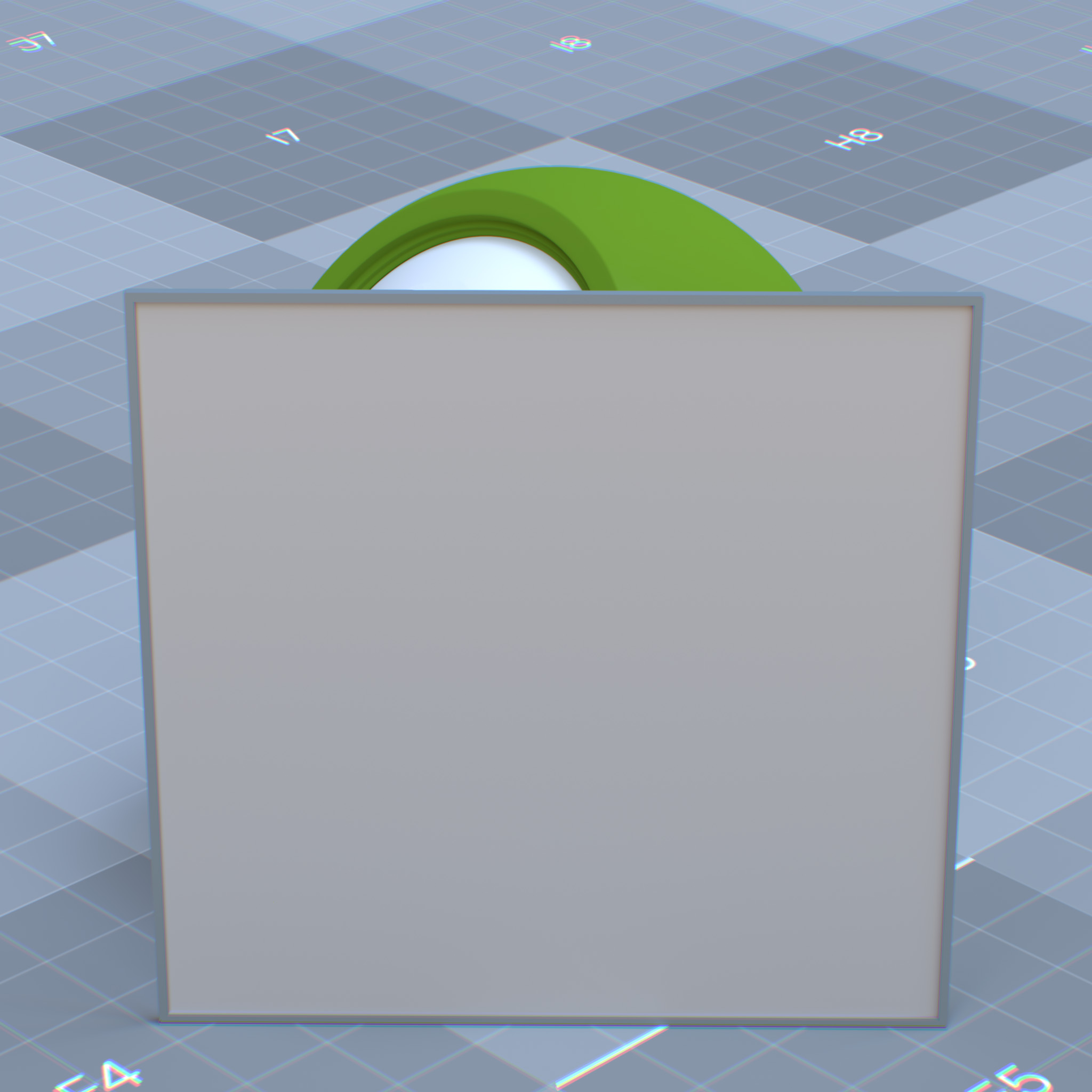
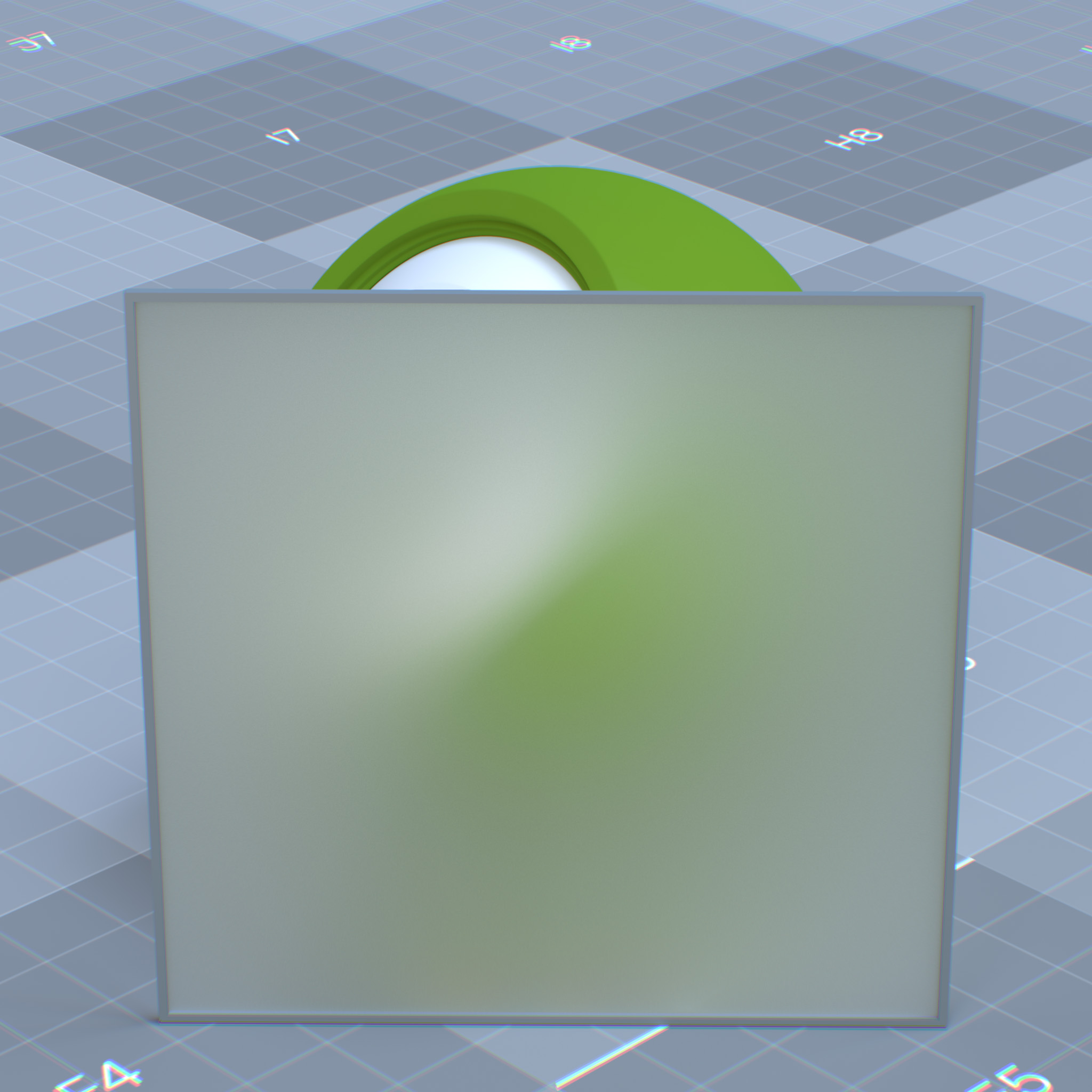
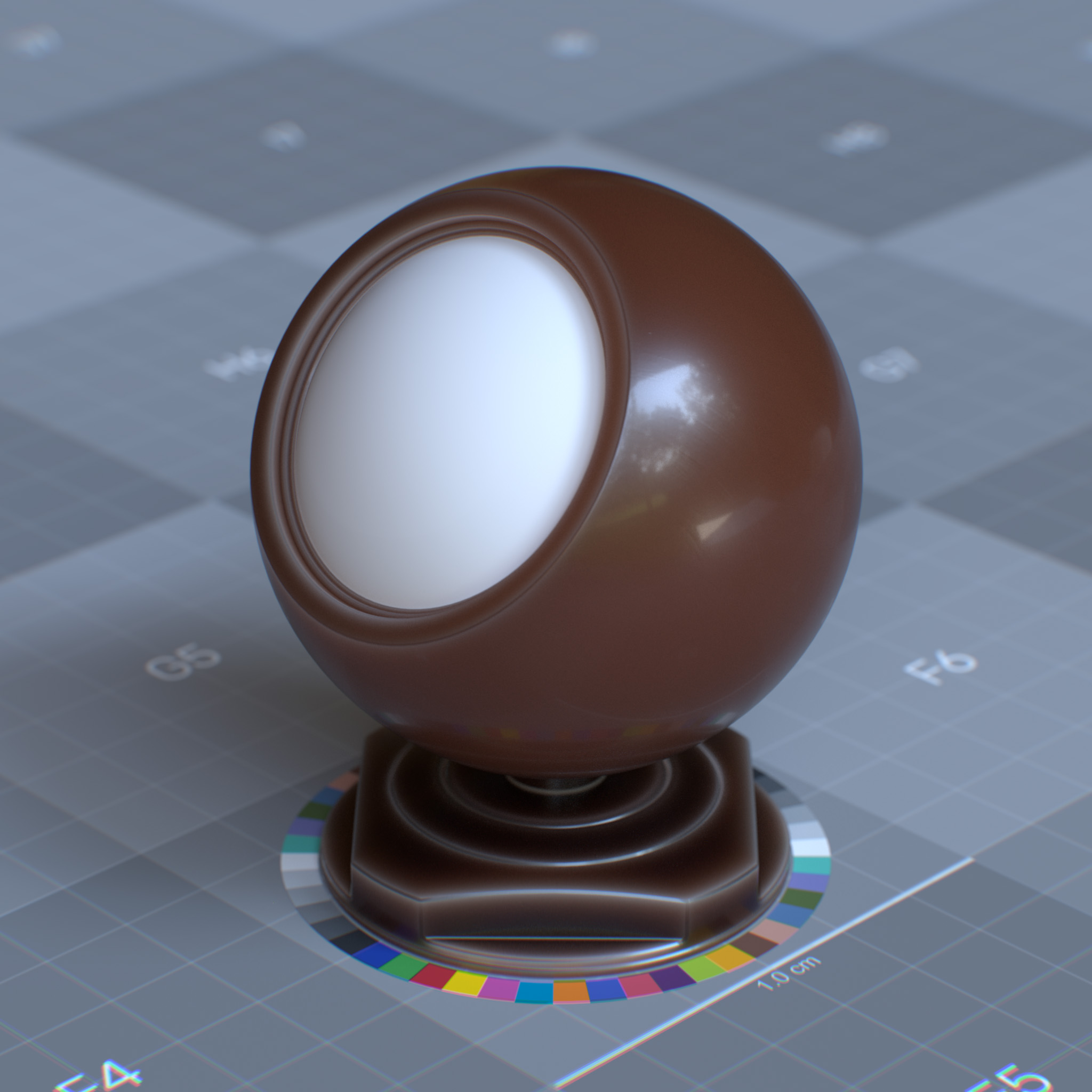
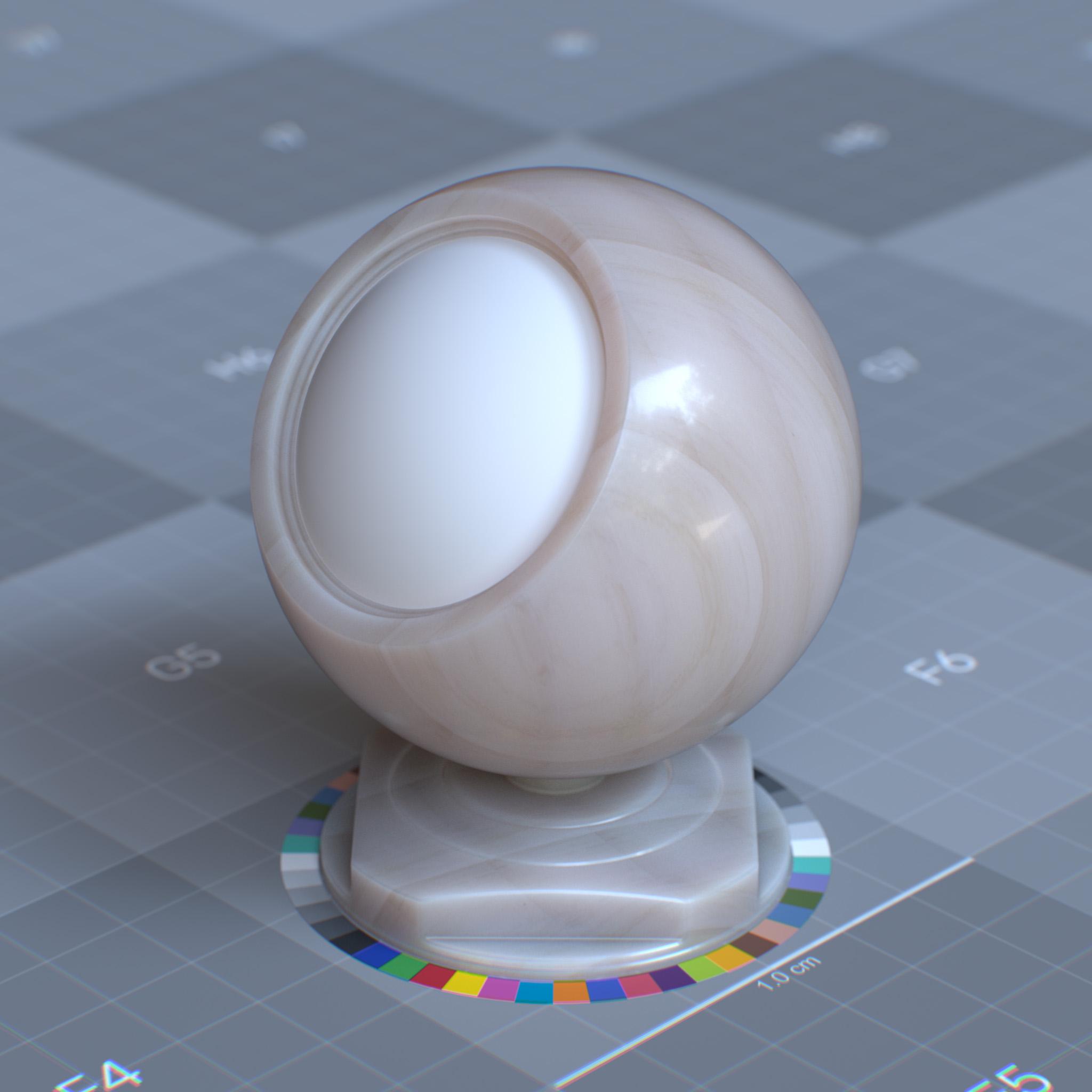
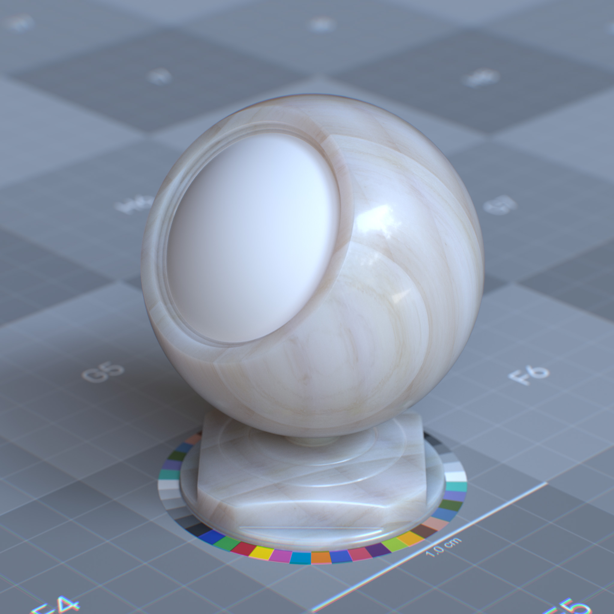
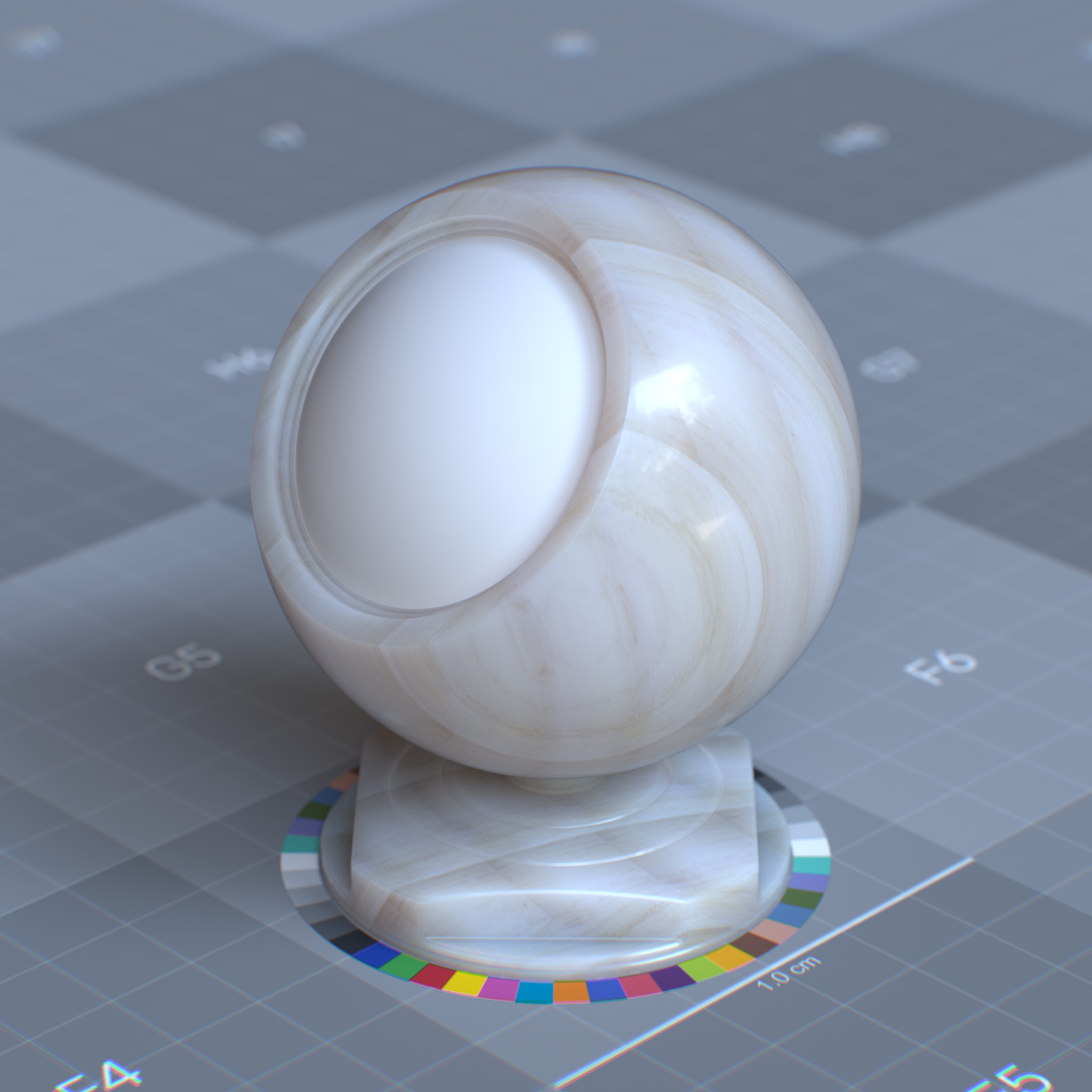
This layer models the effect of light absorption and scattering within a homogeneous medium interior to the object, where the exiting rays leave at a different surface location than the incident rays.
Subsurface can be used to create materials like plastic, marble, skin, wax, milk, and leaf.
In the path-tracer mode, the subsurface component is calculated using the “Random Walk” technique. The Random Walk uses a stochastic or random process to trace the effect of light scattering through an object, with no assumption about geometric features of the object, i.e., local surface flatness, concavities.
In the real-time mode, the subsurface component is calculated by combining the diffusion profile and path tracing techniques. The diffusion profile is based on the Monte Carlo simulation result that describes the distribution of energy coming out of a semi-infinite flat surface of the scattering medium.
If thin-walled enabled, the subsurface represented as the diffuse transmission of light through an infinitely thin shell.
|
|
Note
For a correct result, properly constructed geometry is required, i.e., no self-intersections, closed or geometry with thickness, proper normal directions.
Note
If subsurface appears black in the path-tracer mode, one may need to increase Max Volume Scattering Bounces in the render settings panel. In practice, 32 bounces would be a good starting number.
Please see RTX Interactive (Path Tracing) mode render settings for more information.
|
|
|
|
Enable Subsurface
Enables diffuse transmission and subsurface layer
Weight
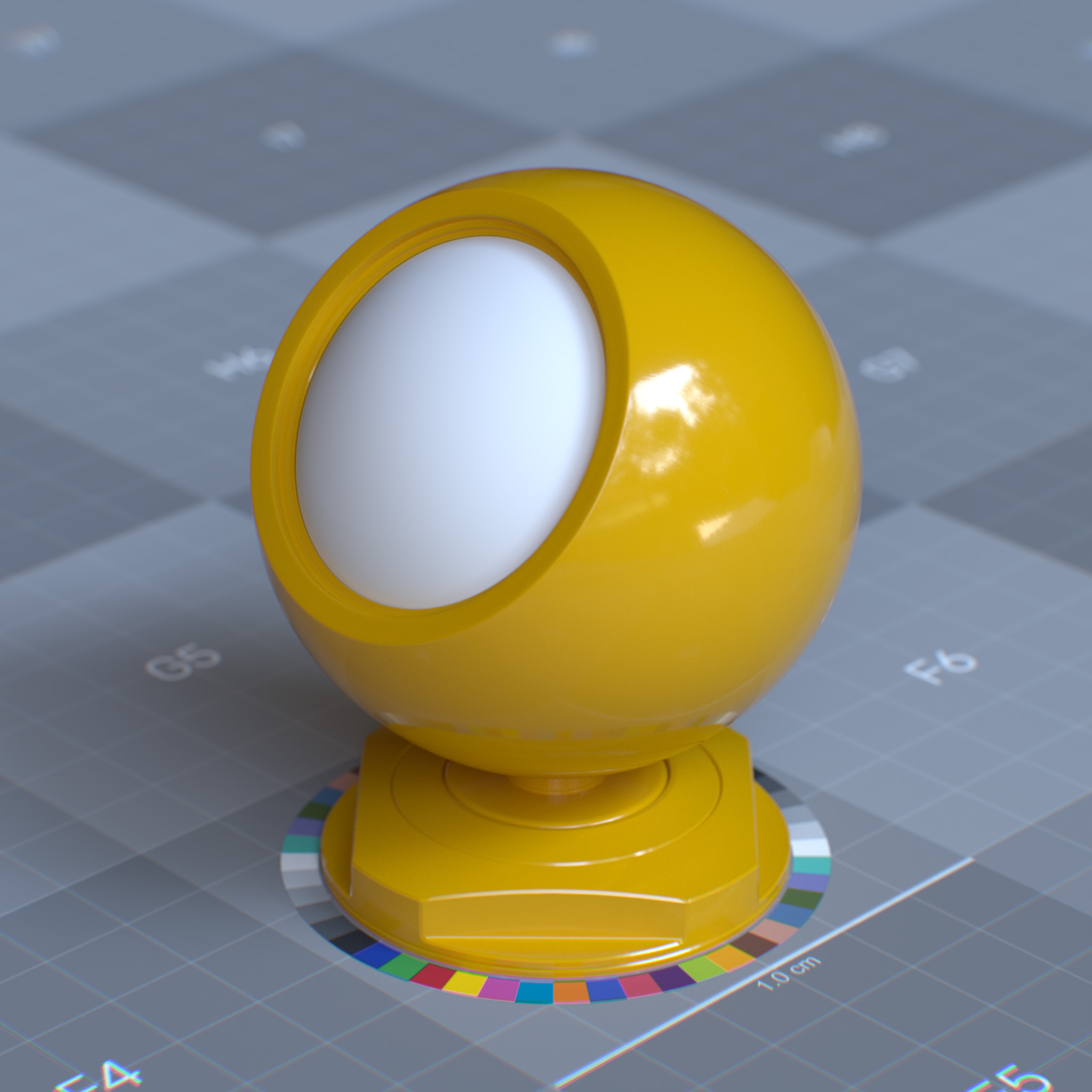
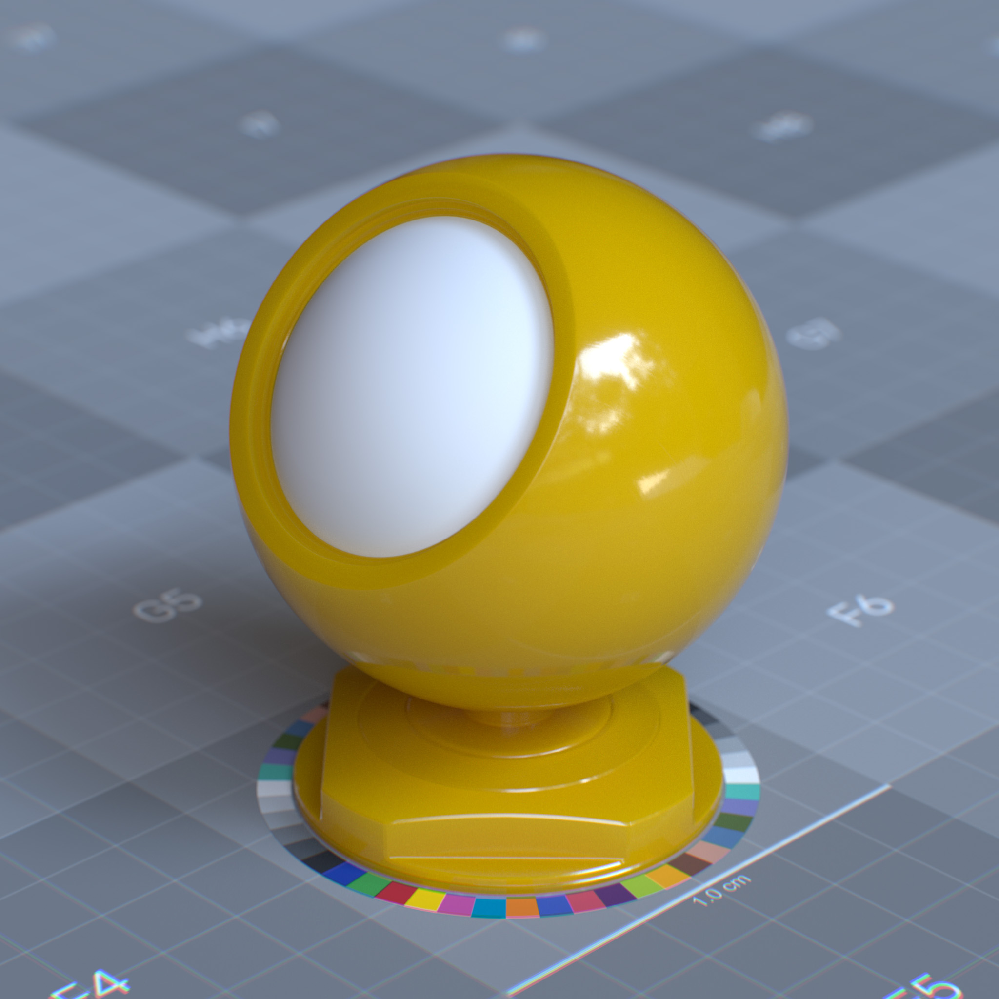
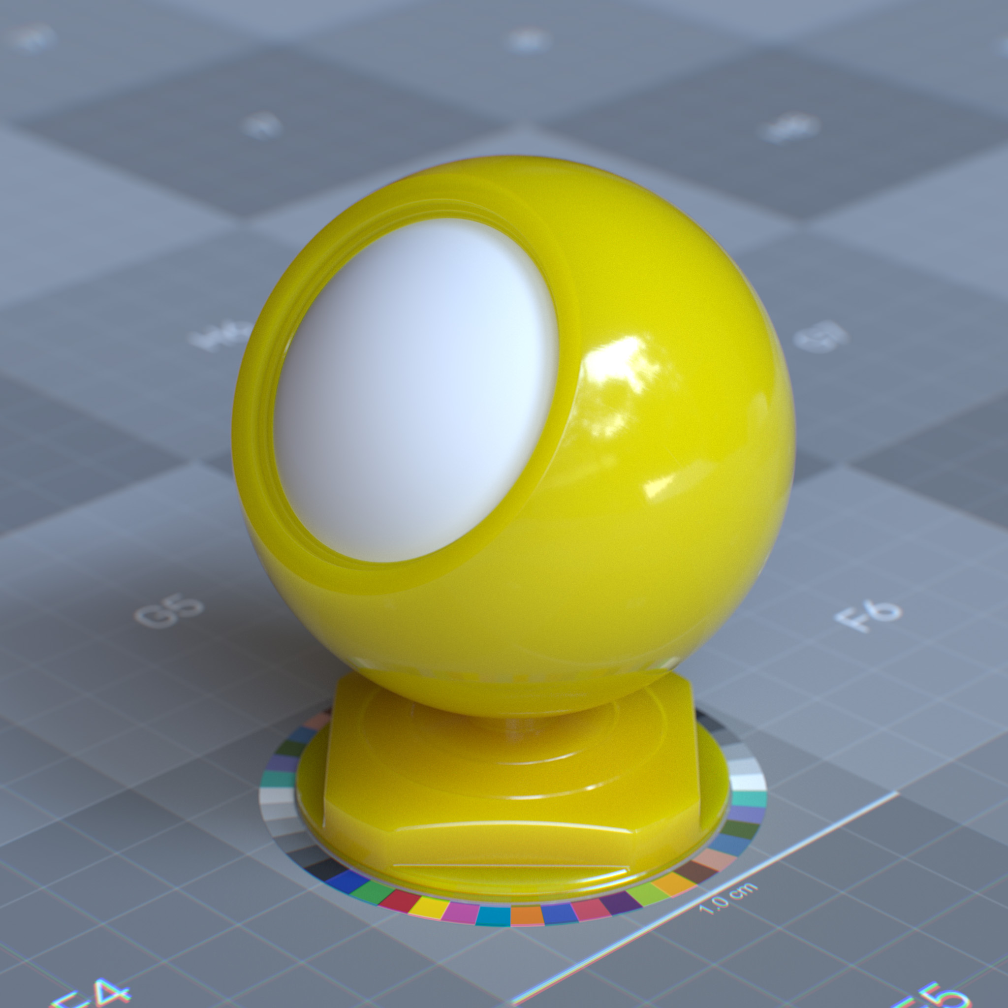
This parameter sets the amount of diffuse transmission and subsurface scattering. At 0.0, the surface is represented as diffuse only surface, and a higher value increases the visibility of diffuse transmission and subsurface scattering.
|
|
|
Scattering Presets
This parameter presents a list of known subsurface scattering colors and radiuses for various materials, including apple, milk, ketchup, skin. One can use custom values by setting this parameter to scattering_colors_custom and set a value for color and radius parameters.
Color
This parameter sets the color of the subsurface scattering effects. When incoming rays reach the surface, they will get tinted by the subsurface color. The subsurface color and radius parameters determine the absorption and scattering within the medium interior to the object.
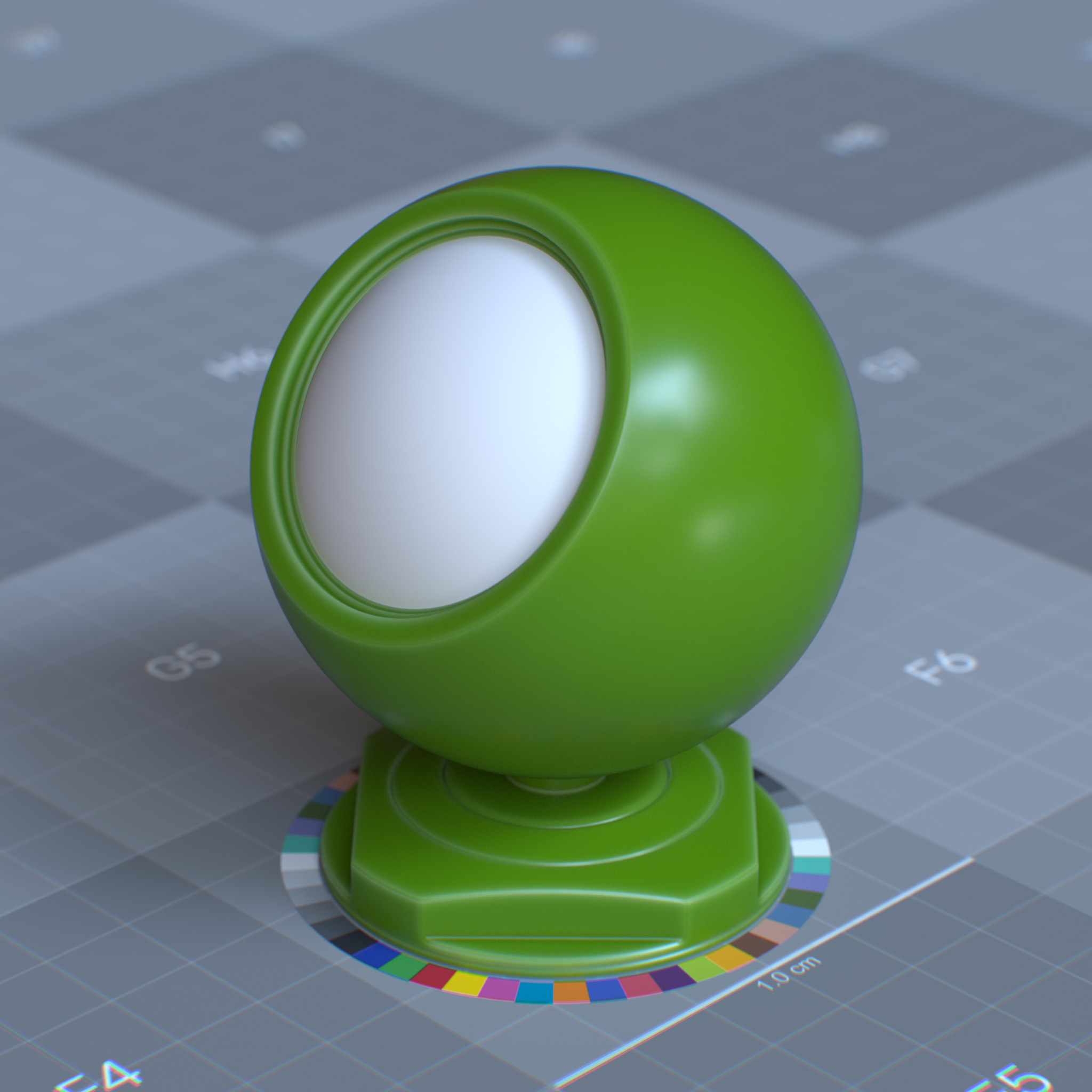
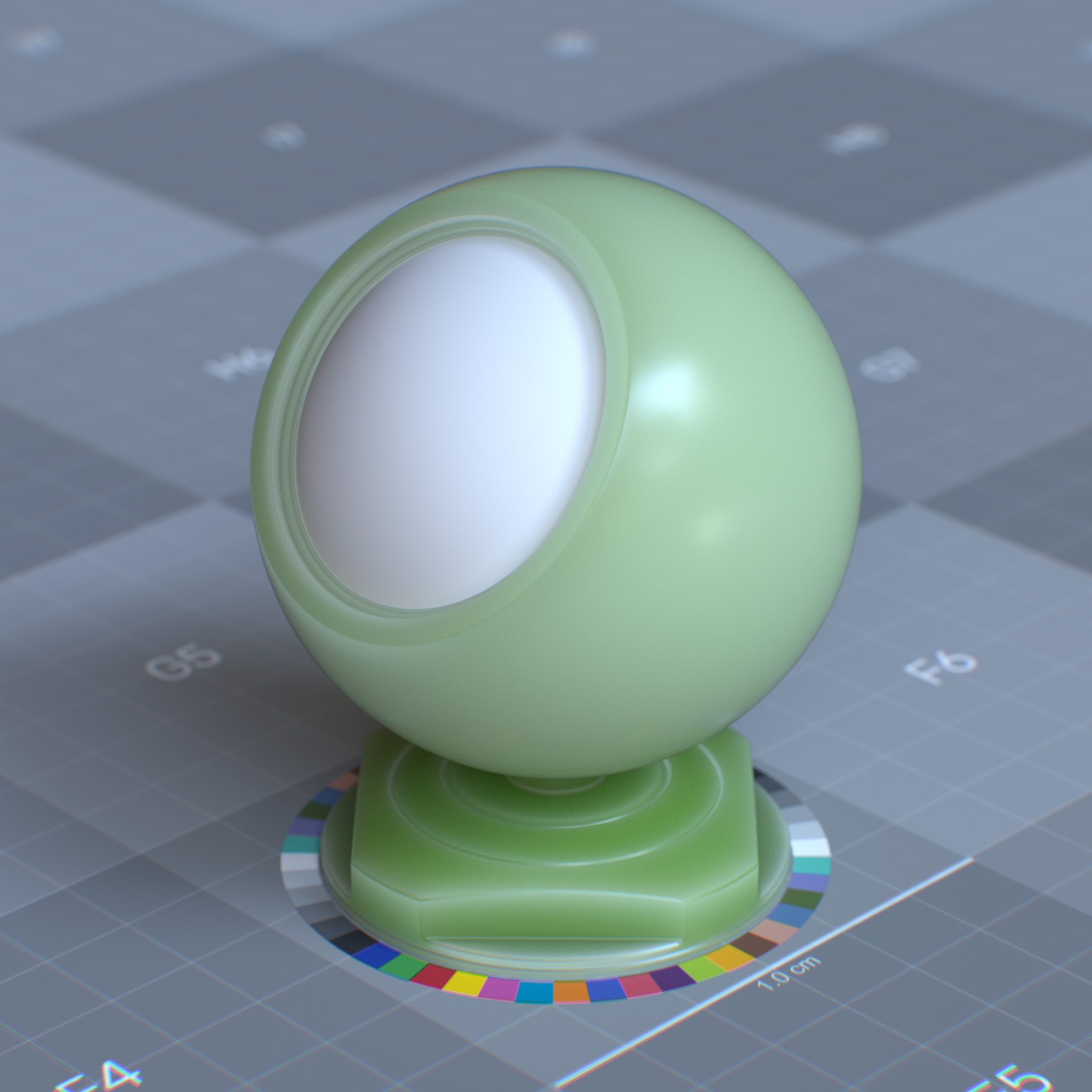
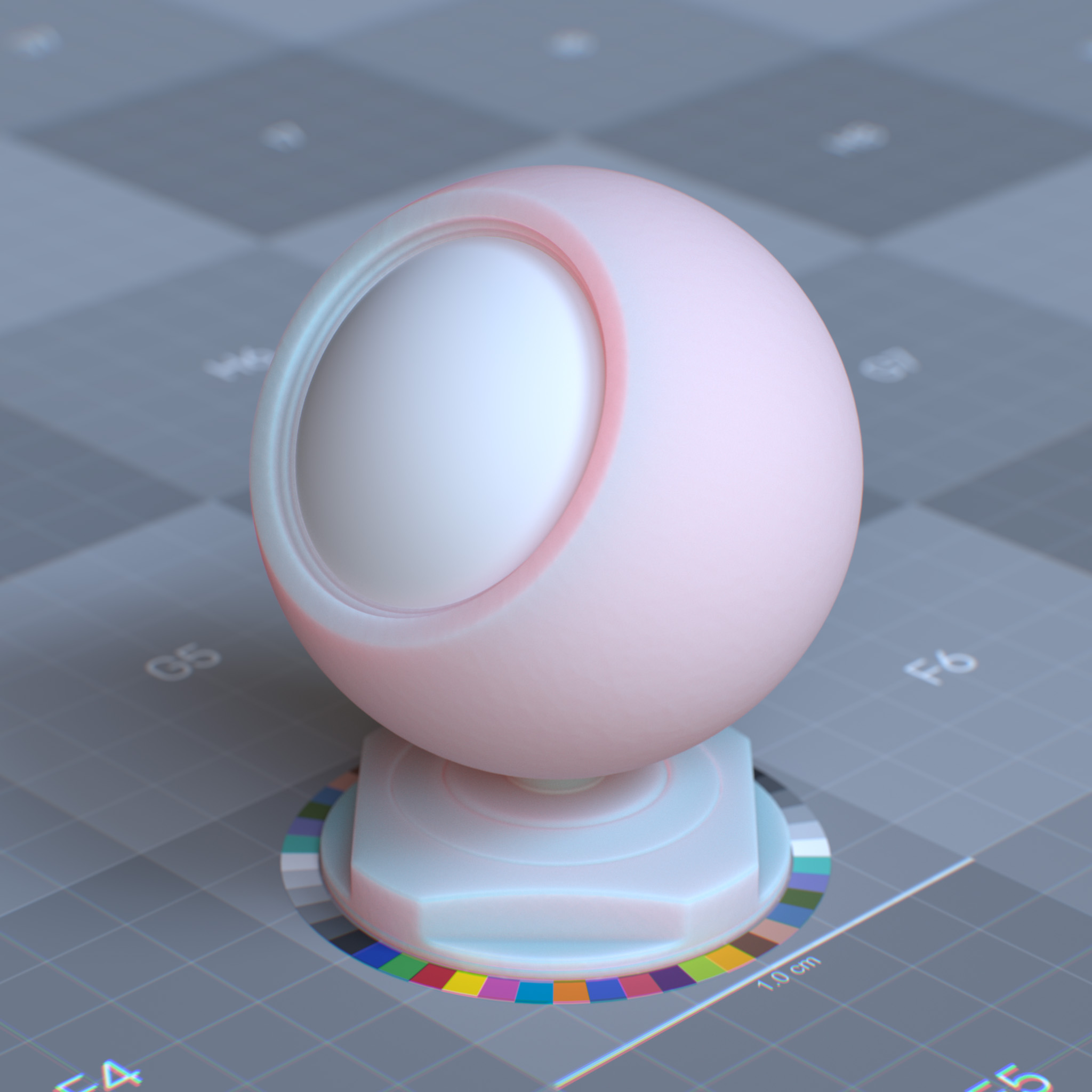
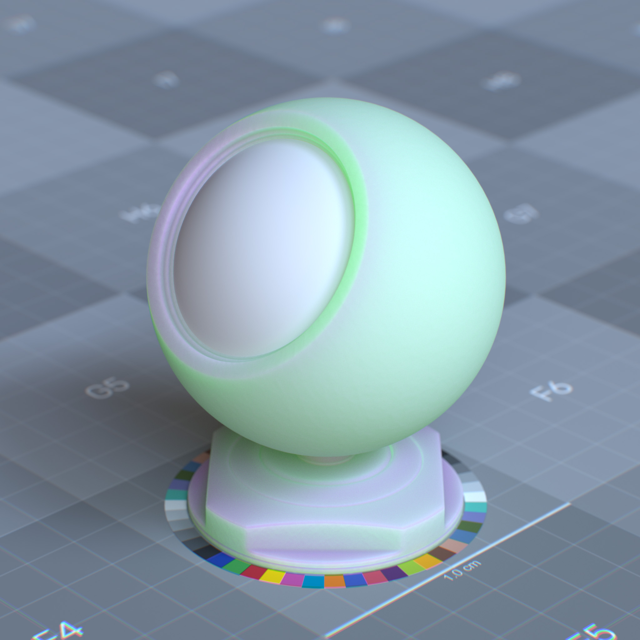
Radius (mfp)
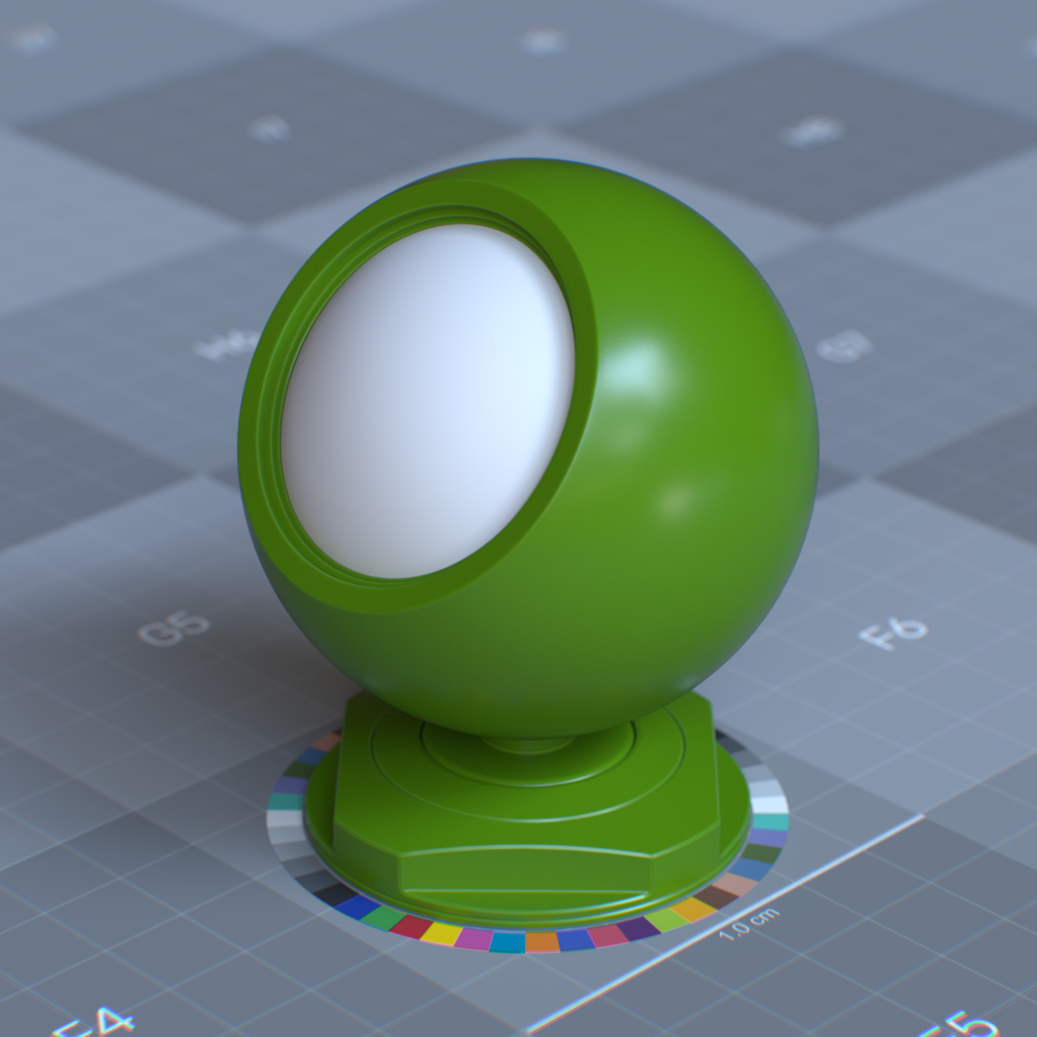
This parameter sets the scattering radius, which describes as the mean free path (mfp). The mean free path is the average distance that rays travel before scattering below the surface and within the volume.
As the rays travel through the volume, they bounce around and emerge from the surface at different locations. This value corresponds to the average length the ray travels between each bounce. The higher the path length is, the further the ray is allowed to scatter within the volume.
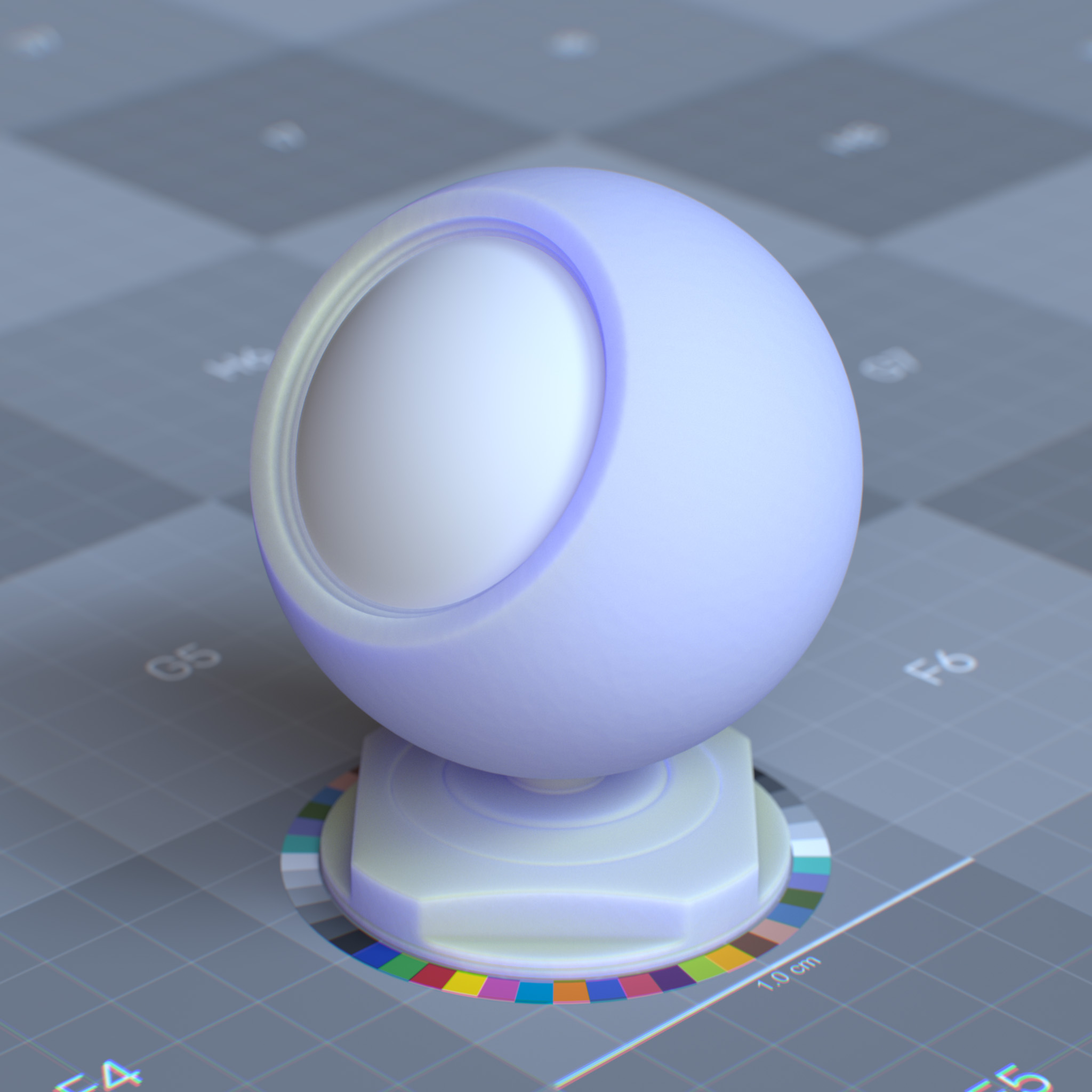
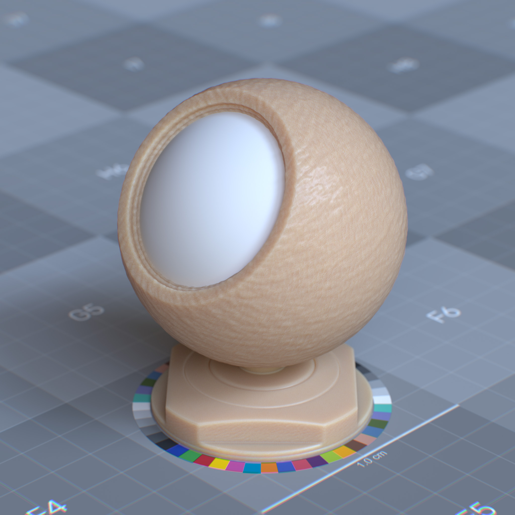
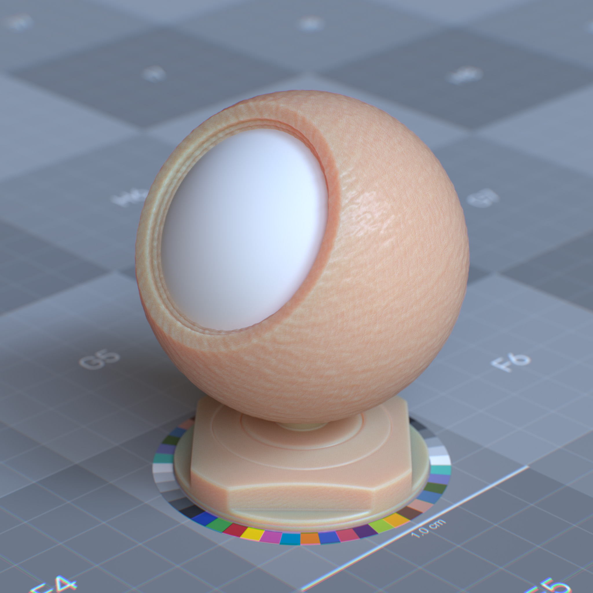
At 0.0, there will be no scattering effect. Lower values mean scattered light is absorbed quicker, resulting in a more opaque look. At higher values, the surface appears more translucent.
|
|
|
The scattering radius can be different per spectra.
|
|
|
For example, skin material would have a higher red value in the radius since red light (620-670nm) penetrates and scatter deepest into the skin compared to green and blue lights.
|
|
The effect of radius depends on the absolute size of the objects, and hence radius is a scene scale-dependent parameter.
Scale
This parameter scales the effect of scattering radius or the mean free path distance. If the scene is not modeled to scale, the scale parameter can be used to adjust the scattering effect. Lowering this value makes the object more diffuse, while at a higher value, it becomes more translucent.
The Scale parameter is adjusted based on the scene unit; if the scene scale is in meter, the scale of 1.0 corresponds to 1.0 meter.
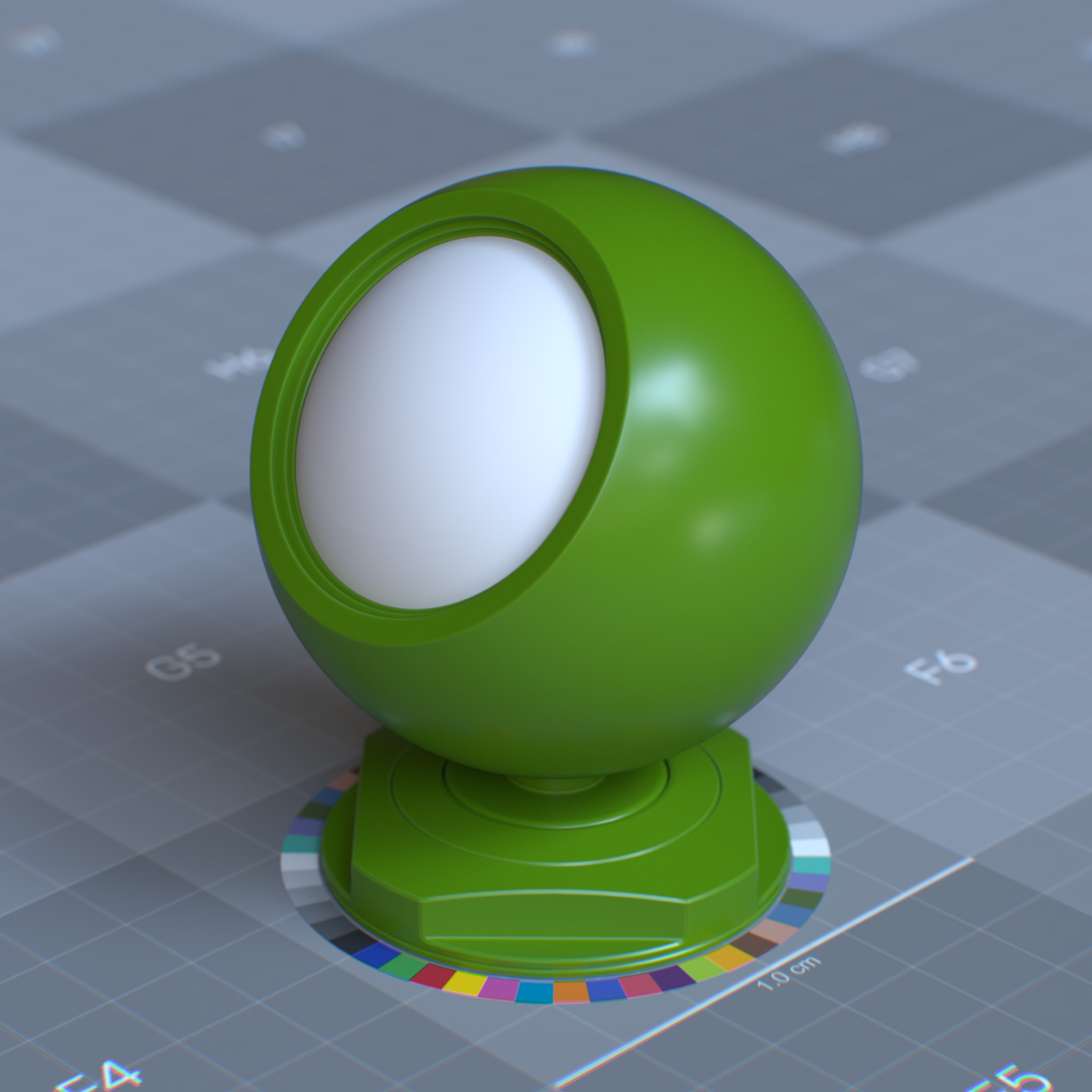
Subsurface Radius: 1.0, 1.0, 1.0_scale_0p001.jpg# |
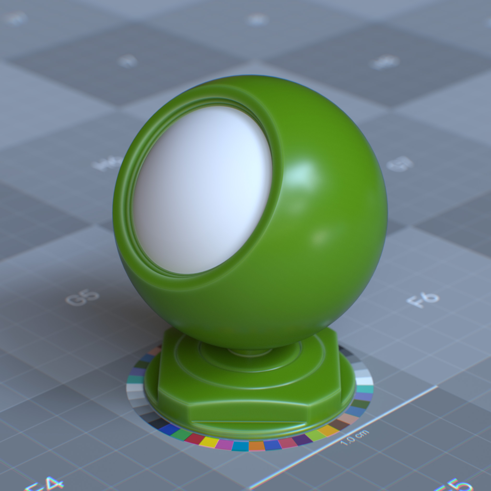
Subsurface Radius: 1.0, 1.0, 1.0# |
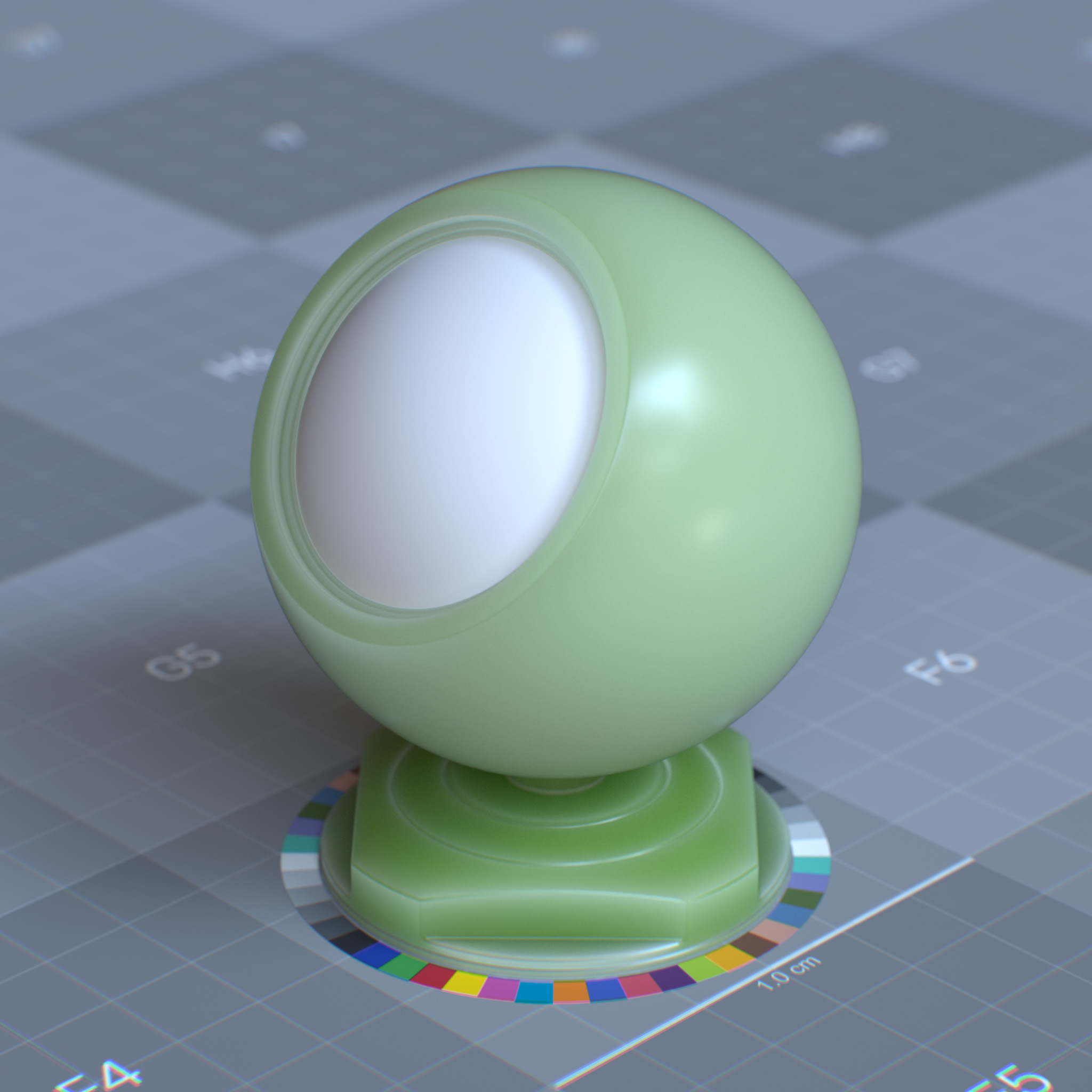
Subsurface Radius: 1.0, 1.0, 1.0# |
Anisotropy
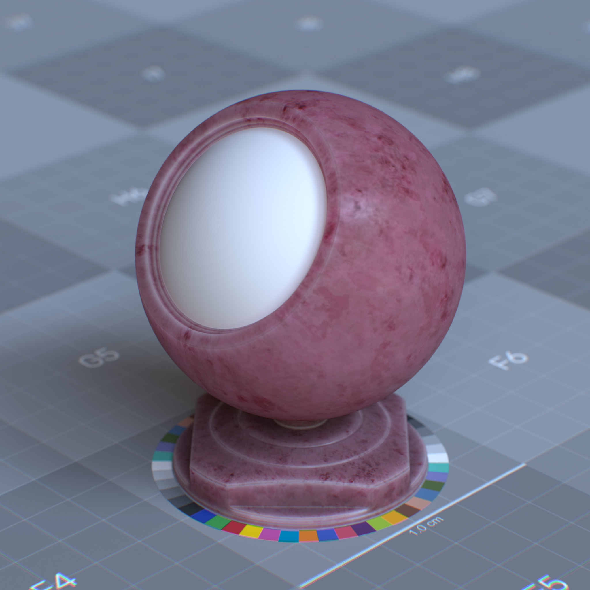
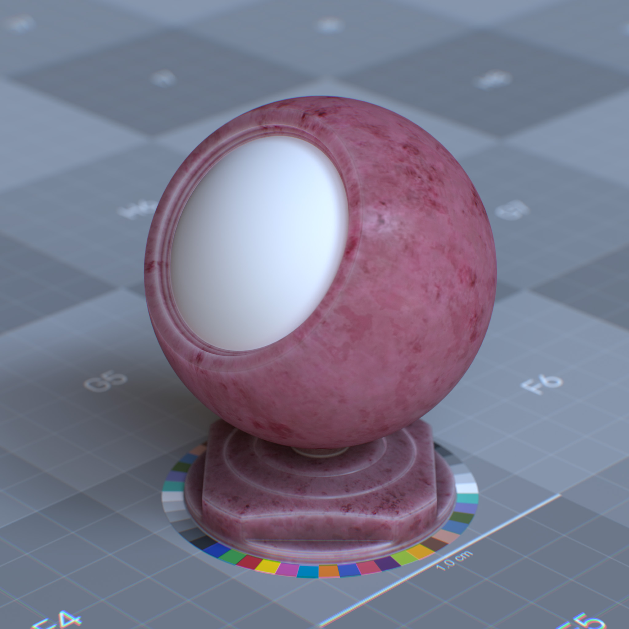
This parameter sets the scattering directionality or anisotropy of the “Henyey-Greenstein” phase function of the interior medium to the object. At 0.0, scattering sets to isotropic, and light is scattered uniformly in all directions. Values above 0.0 biases the scattering effect forward in the direction of the light, while values below 0.0 biases the scattering effect backward in the opposite direction of the light.
Tip
Unlike hard materials, i.e., jade and marble, water-based materials, i.e., orange juice, ketchup, and skin, exhibit strong forward scattering.
|
|
|
Coat
Coat simulates an additional transparent layer on top of a base material, common in automotive paints, polished wood, and plastic coatings. This layer adds a second specular reflection with its own roughness and intensity values, independent of the underlying material properties.
Parameters
Display Name |
Name |
Type |
Default |
|---|---|---|---|
weight |
coat_weight |
float |
0.0 |
color |
coat_color |
color |
1.0, 1.0, 1.0 |
Roughness |
coat_roughness |
float |
0.1 |
IOR Preset |
coat_ior_preset |
enum |
ior_custom |
IOR |
coat_ior |
float |
1.5 |
Anisotropy |
coat_anisotropy |
float |
0.0 |
Rotation (rad) |
coat_anisotropy_rotation |
float |
0.0 |
Affect Color |
coat_affect_color |
float |
0.0 |
Affect Roughness |
coat_affect_roughness |
float |
0.0 |
Normal |
coat_normal |
float3 |
state::normal() |
This layer models GGX microfacet dielectric BRDF top coating. Due to Fresnel, this layer is not energy conserving. Thus the energy that is not reflected is transmitted to the underlying layers.
The coating simulates an infinitely thin shell dielectric layer, i.e., glass, enamel, lacquer, over the surface. It can create materials like metallic car paint, carbon fiber, oily skin, and wet asphalt.
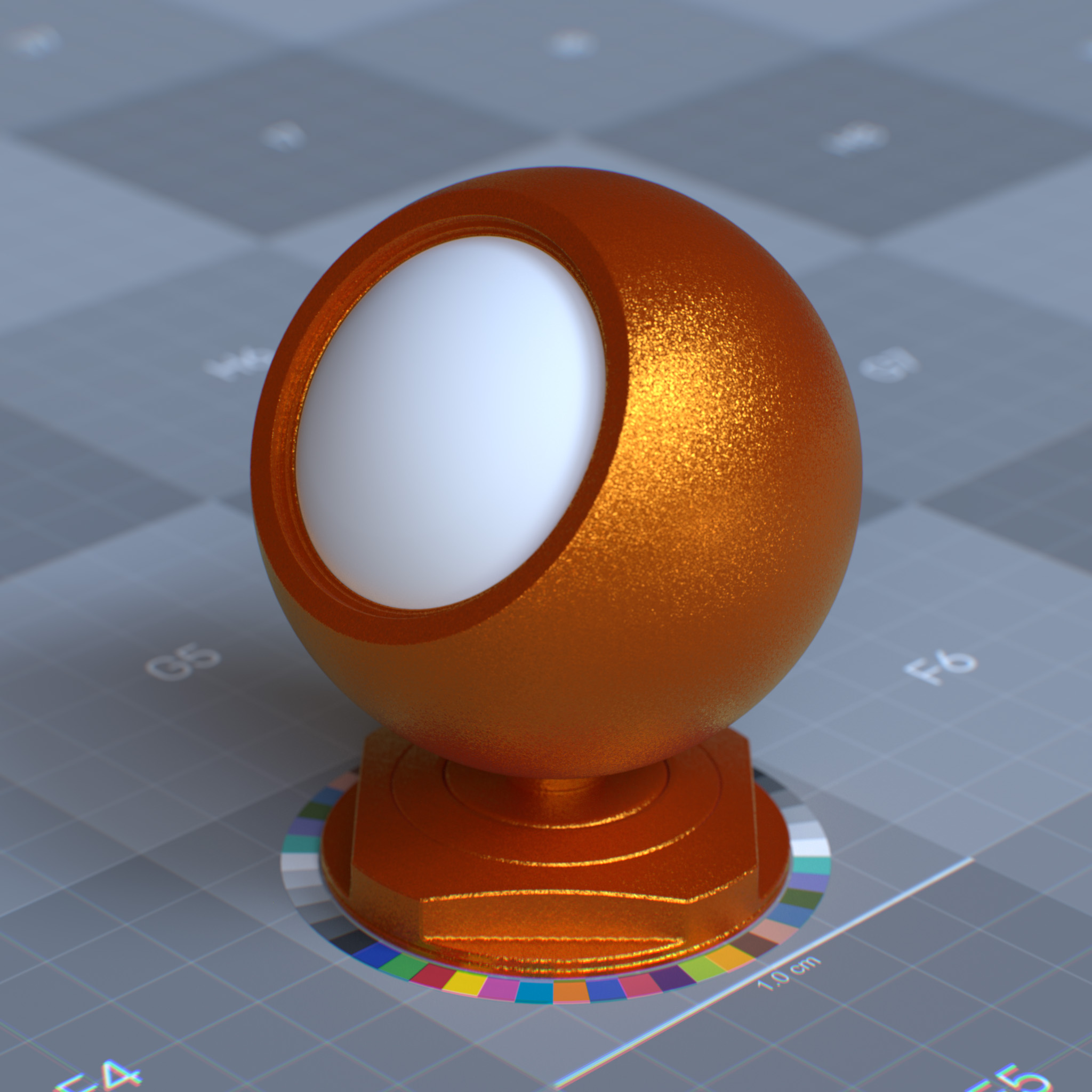
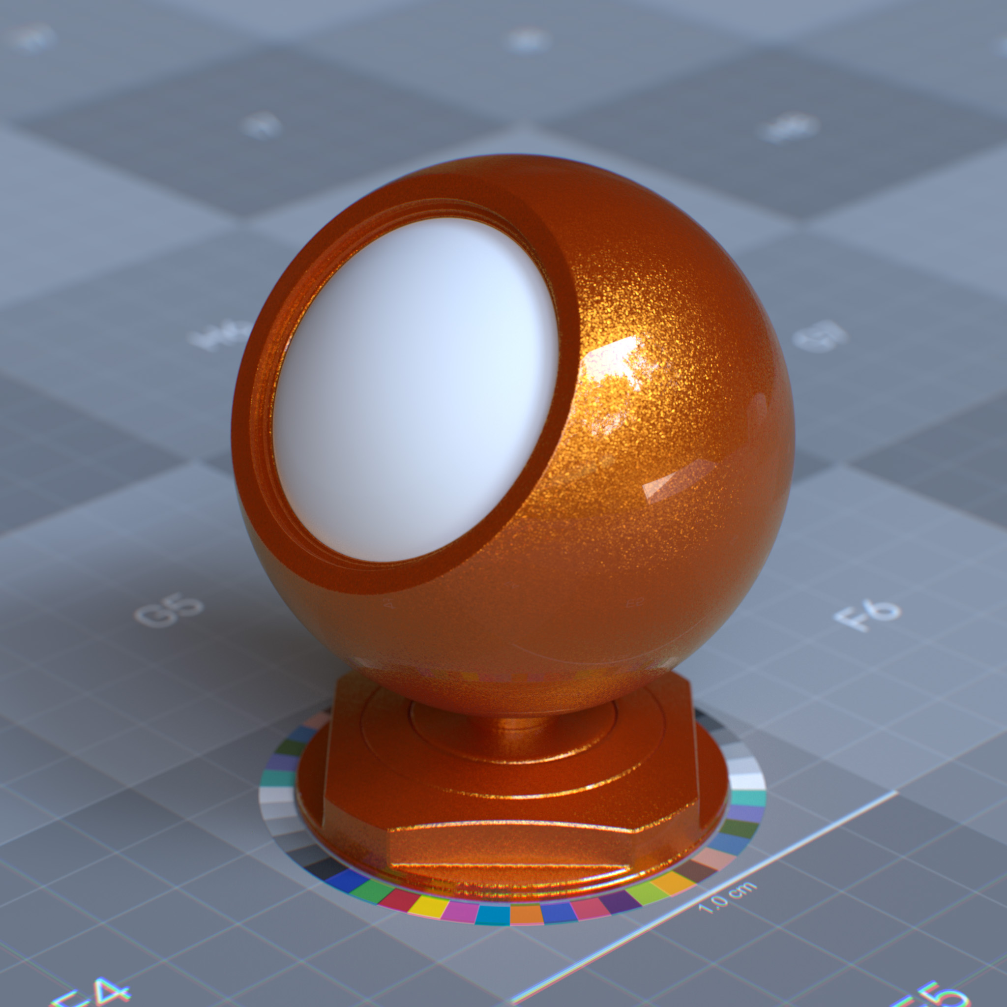
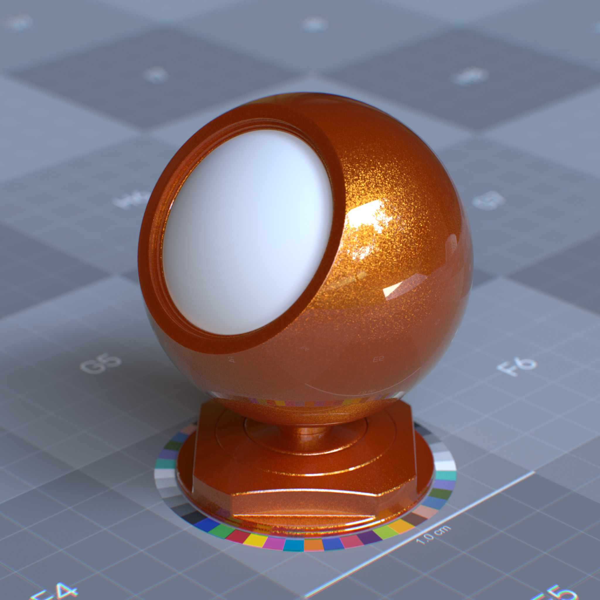
Weight
This parameter sets the amount of surface coating. Lowering this value increases light transmission through the object’s volume.
Tip
For a realistic result, this parameter should be set to less than 1.0.
|
|
|
Color
This parameter tints all layers below the coating layer. In the real world, lights scattered by underlying layers are tinted when transmitted through the colored coating.
This parameter emulates the effect of absorption within the coating medium.
Note
The reflection color is set to white for this layer.
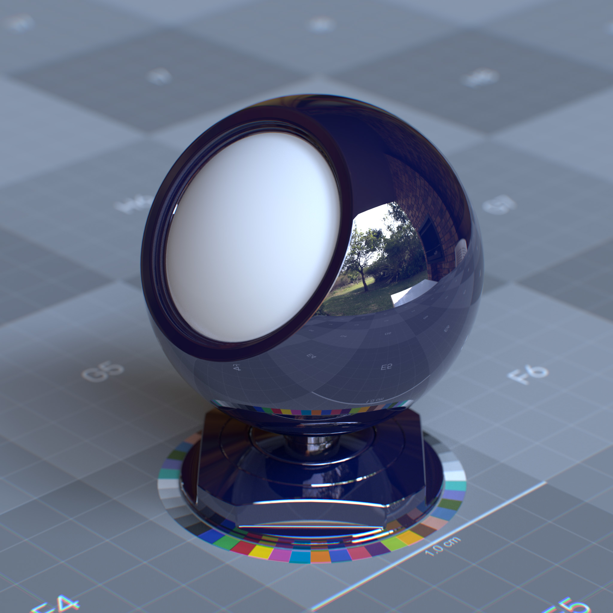
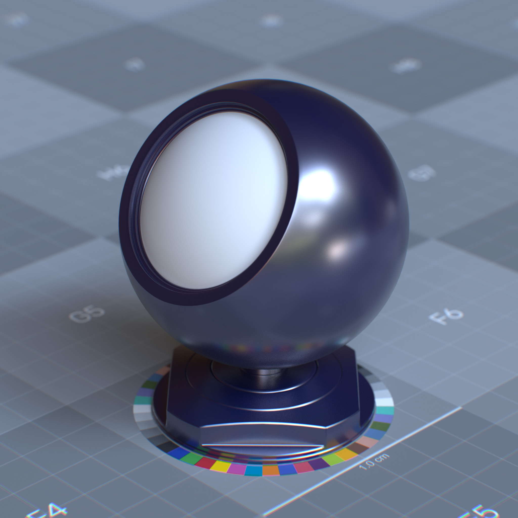
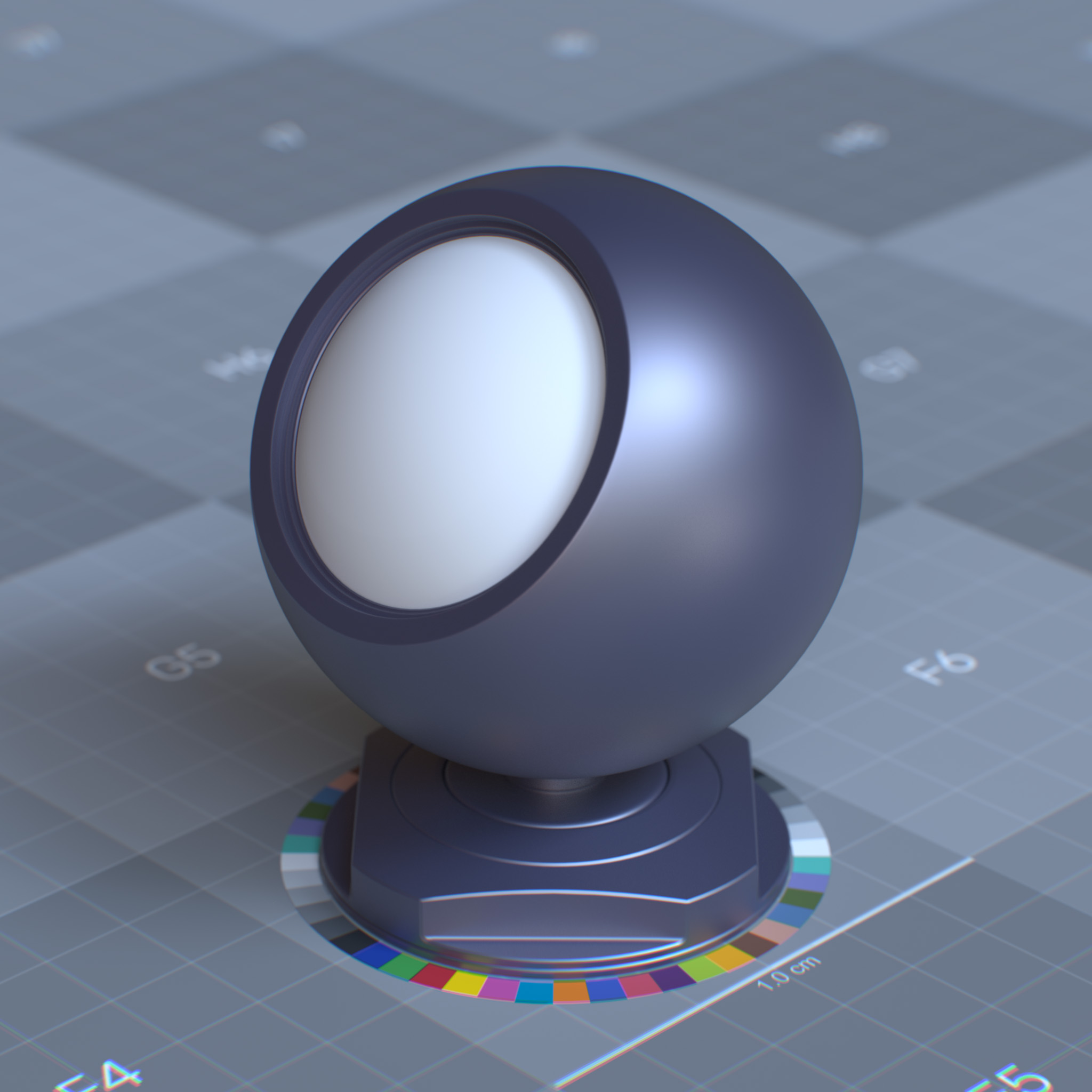
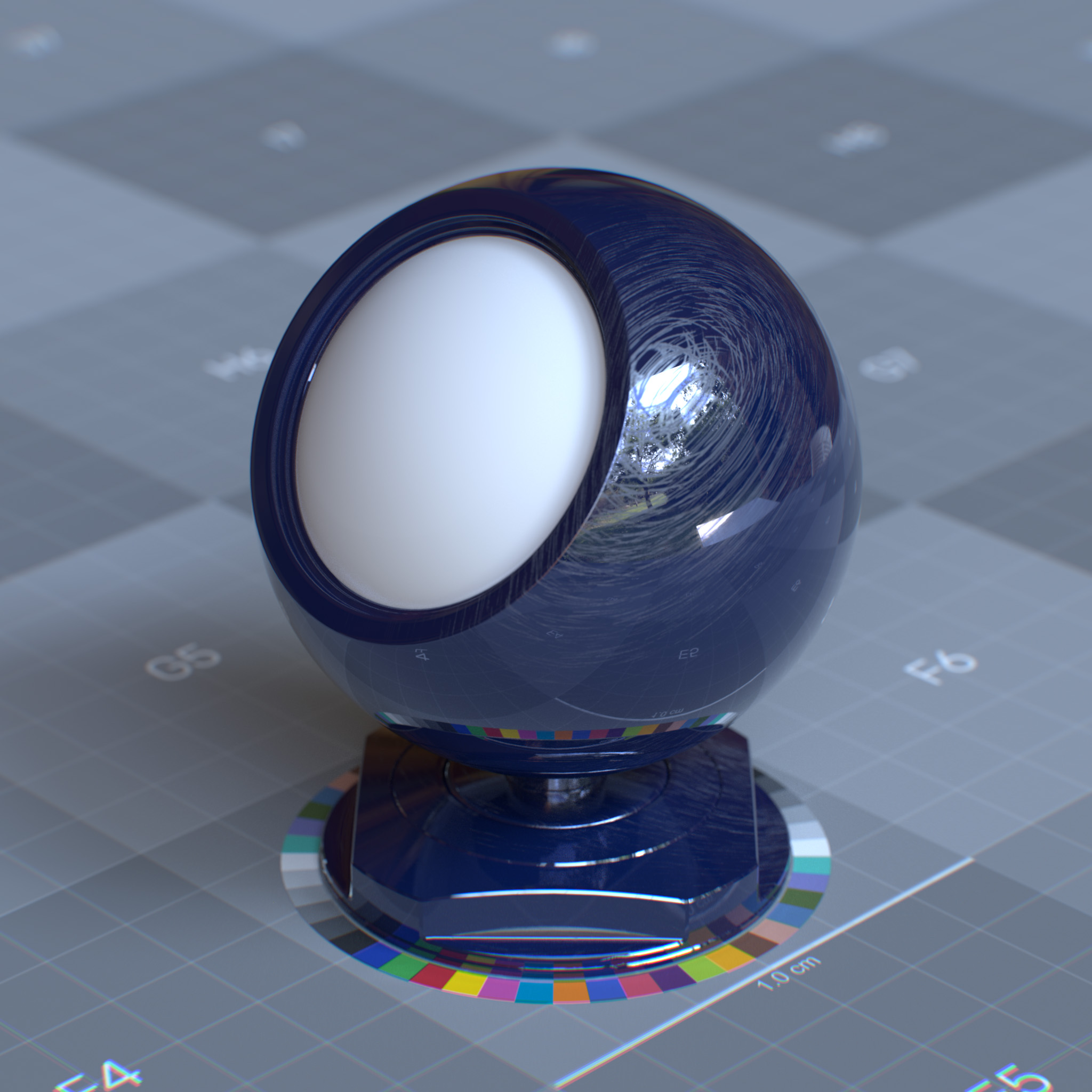
Roughness
This parameter sets the surface microfacet’s irregularities that cause light diffusion. At 0.0 simulates a perfect and smooth reflective surface, while increasing the value causes reflective highlights to diverge or appear blurred.
Tip
Roughness can be used to create effects like torn surfaces or surfaces with fingerprints and smudges.
|
|
|
|
IOR Preset
This parameter presents a list of known IORs (index of refractions) for various materials, including glass, ice, diamond, skin. One can use custom IOR by setting this parameter to ior_custom and a value for the specular reflection’s IOR parameter.
IOR
This parameter sets IOR (index of refraction), which affects surface Fresnel reflectivity. The IOR defines the ratio between reflection on the surface front, facing the viewer, and the surface edges, facing away the viewer.
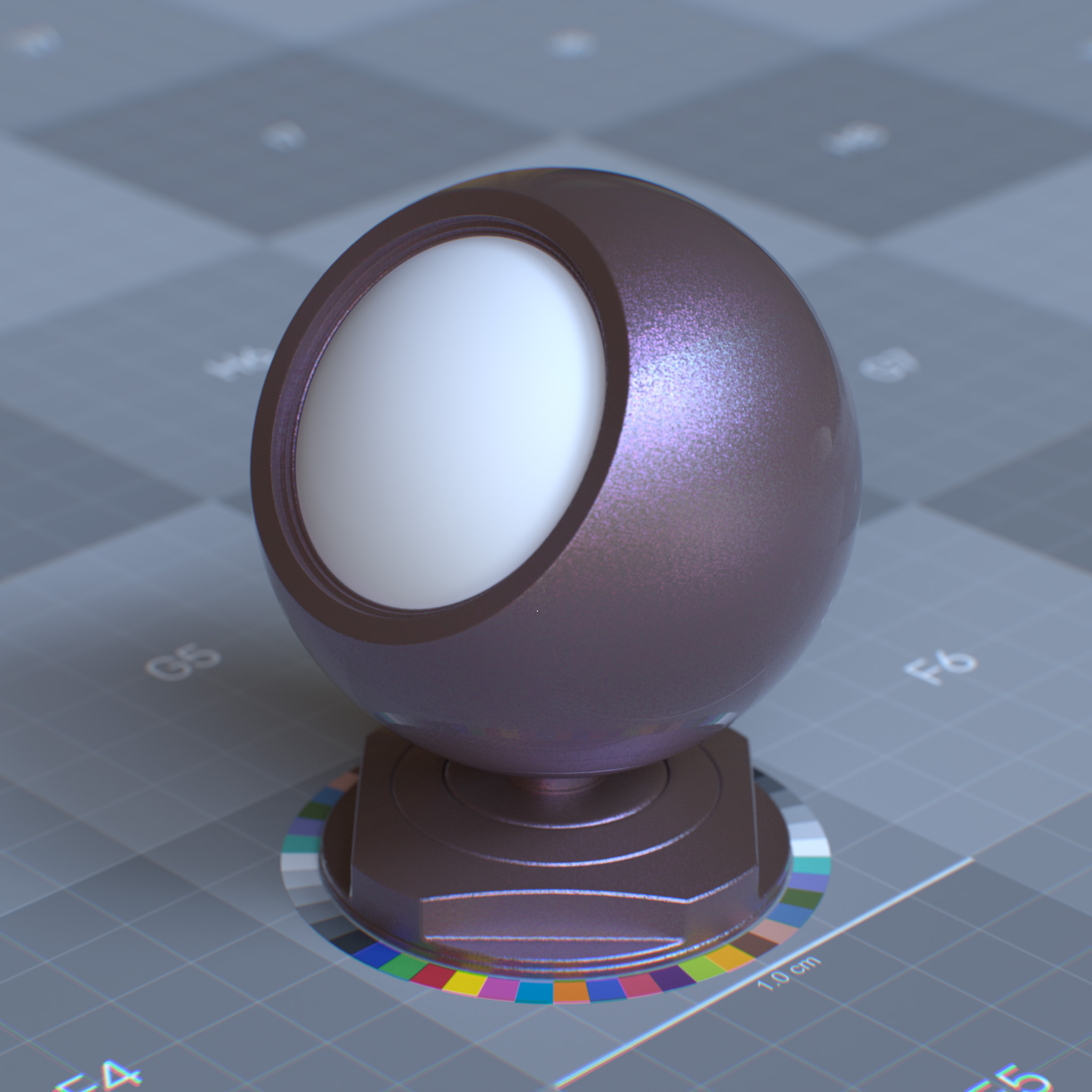
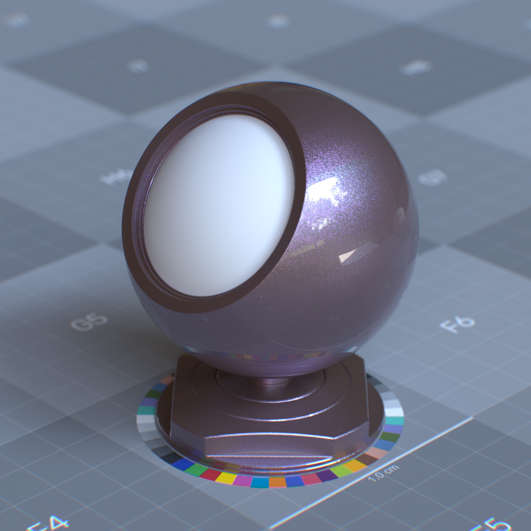
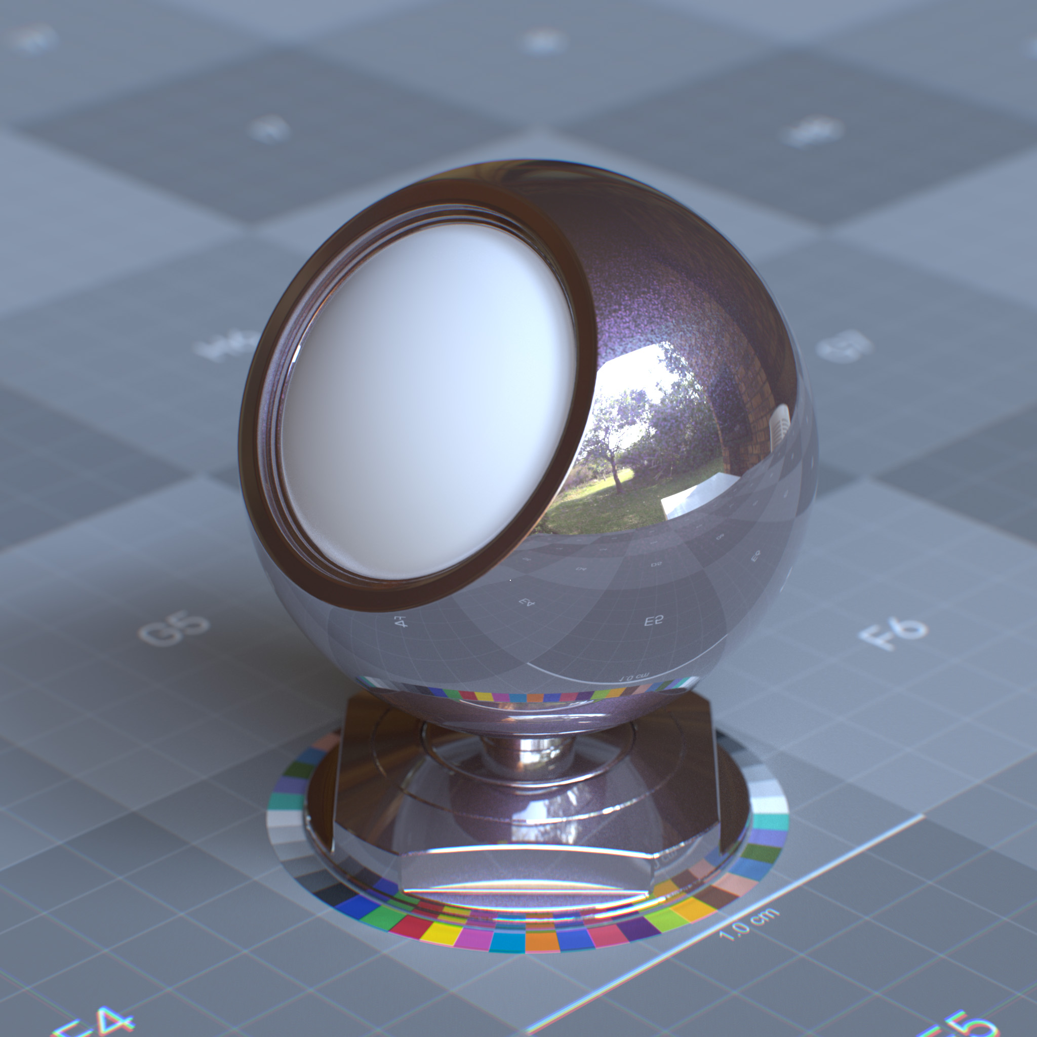
At values above 1.0, the reflection appears stronger on the surface edges and weaker on the surface front. At values less than 1.0, the Fresnel is disabled, and the coating appears as a uniform highlight over the surface.
|
|
|
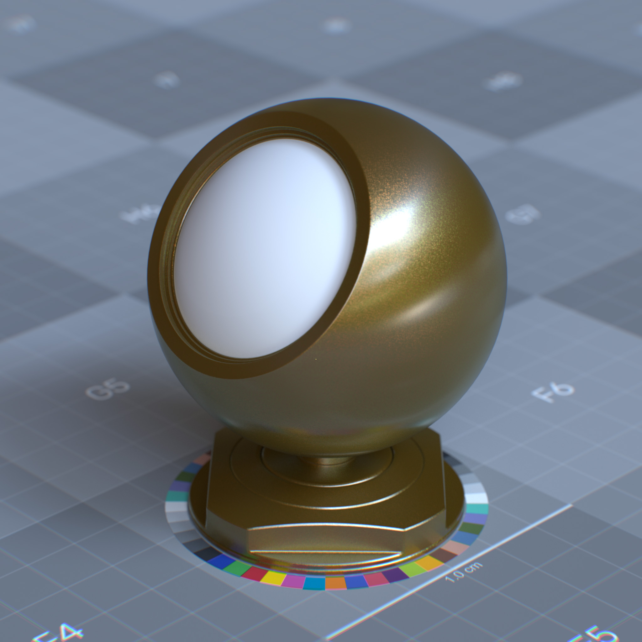
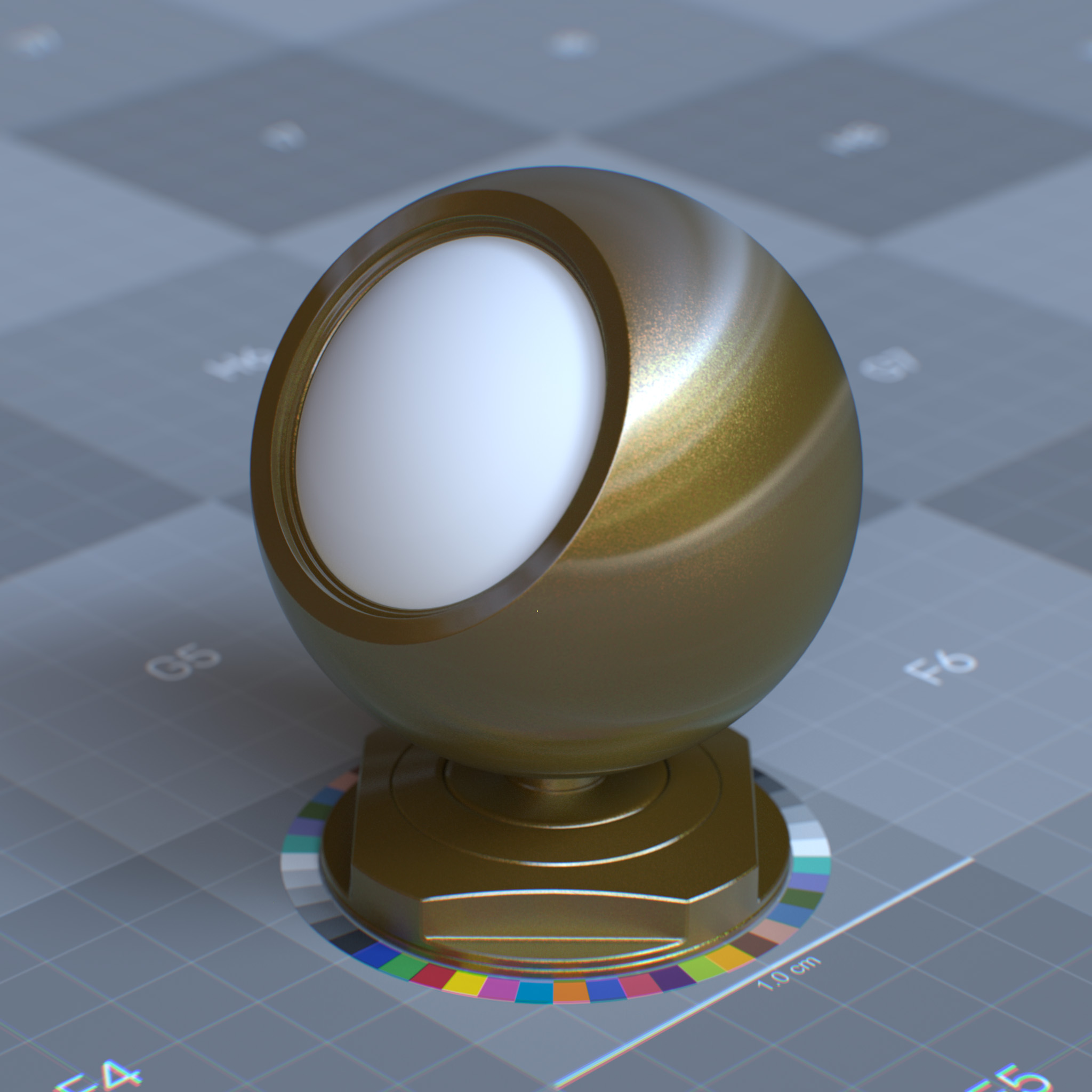
Anisotropy
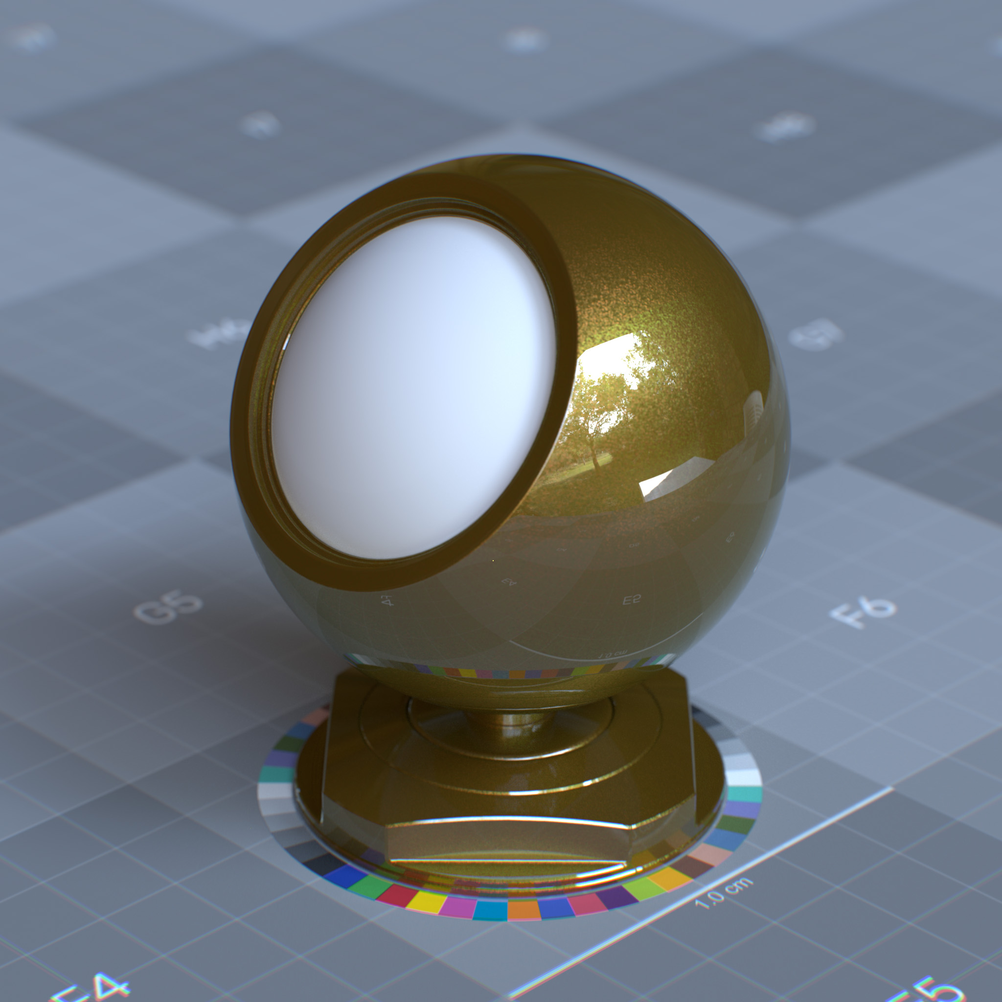
his parameter sets the specular reflection anisotropy. Reflectance changes based on the surface orientation are called anisotropic. If the reflectance is uniform in all directions and does not change based on the surface’s rotation or orientation, it is isotropic.
At values above 0.0, the surface transmits and reflects incoming light with a directional bias. Thus it appears rougher in a specific direction.
|
|
|
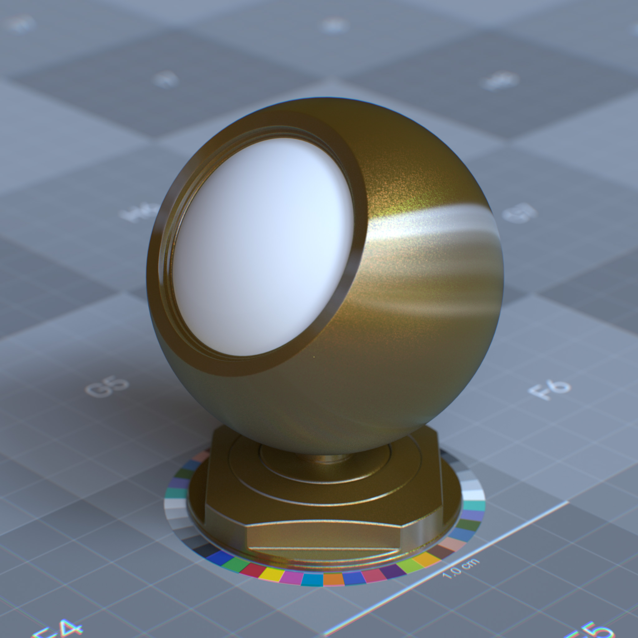
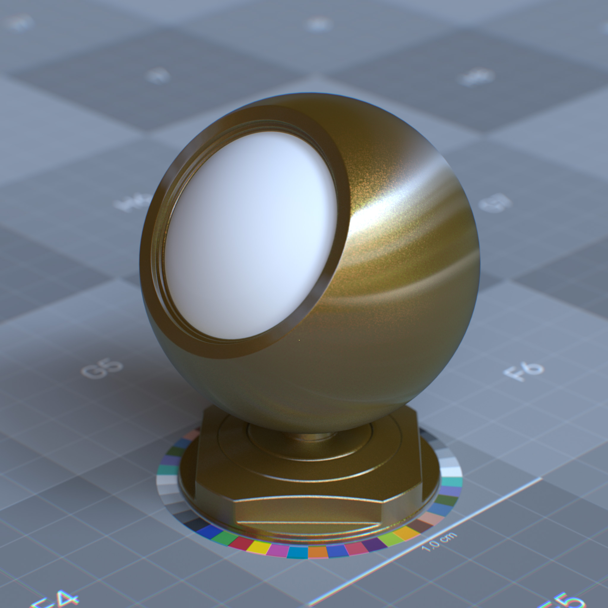
Rotation (radian)
This parameter sets the orientation of the anisotropic effect in radians. At 1.0, the anisotropic effect is rotated by 180 degrees. For brushed surfaces, the anisotropic effect should stretch out in a direction perpendicular to the brushing direction.
|
|
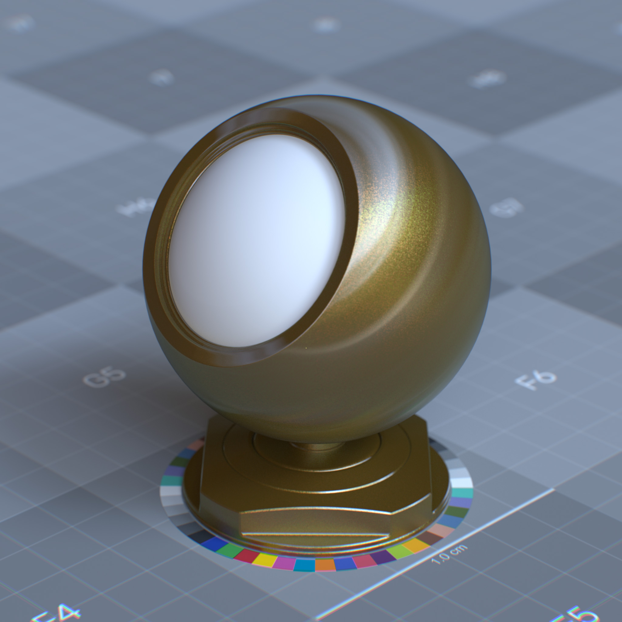
|
Affect Color
This parameter controls the saturation of diffuse reflection and subsurface under the coating layer.
In the real world, refracted rays exhibit internal reflection within the coating medium, which can go back down to the underlying surface to reflect again, thus making the surface more saturated and darker. Affect Color can be used to emulate this effect. At 0.0, this parameter has no effects.
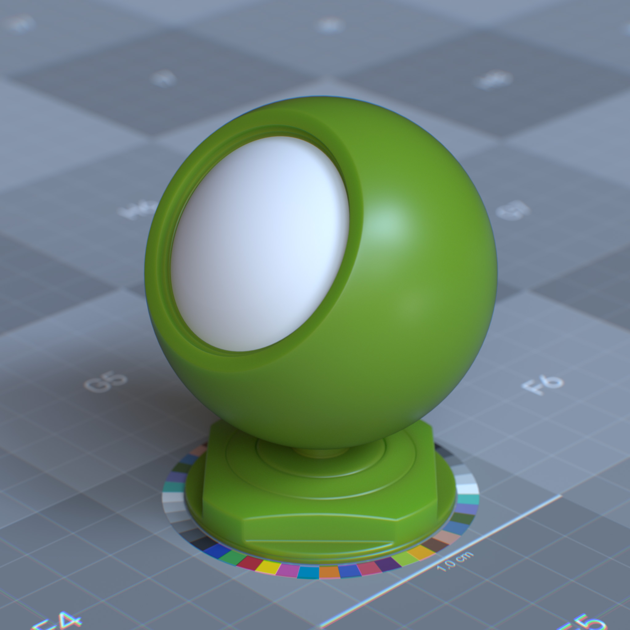
|
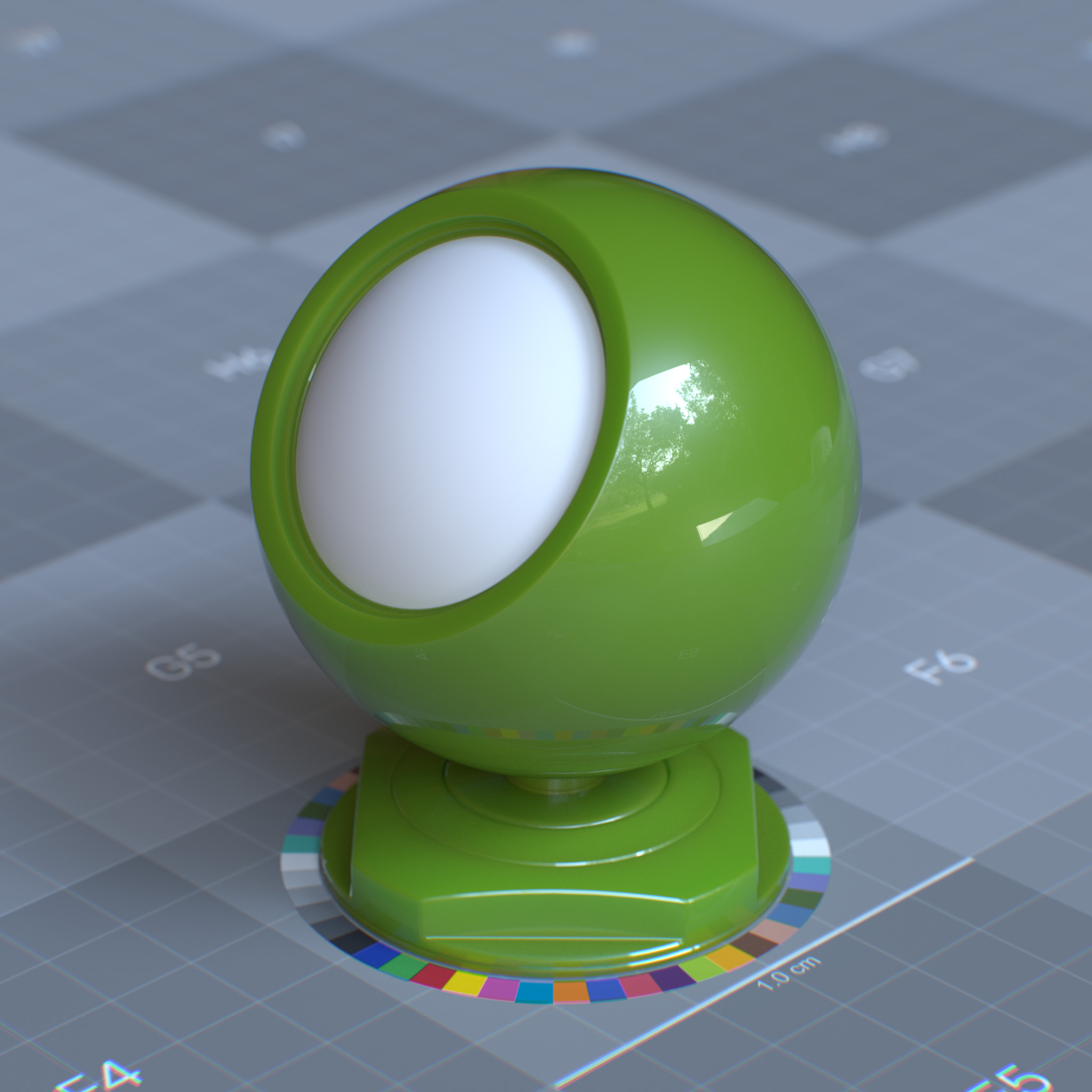
|
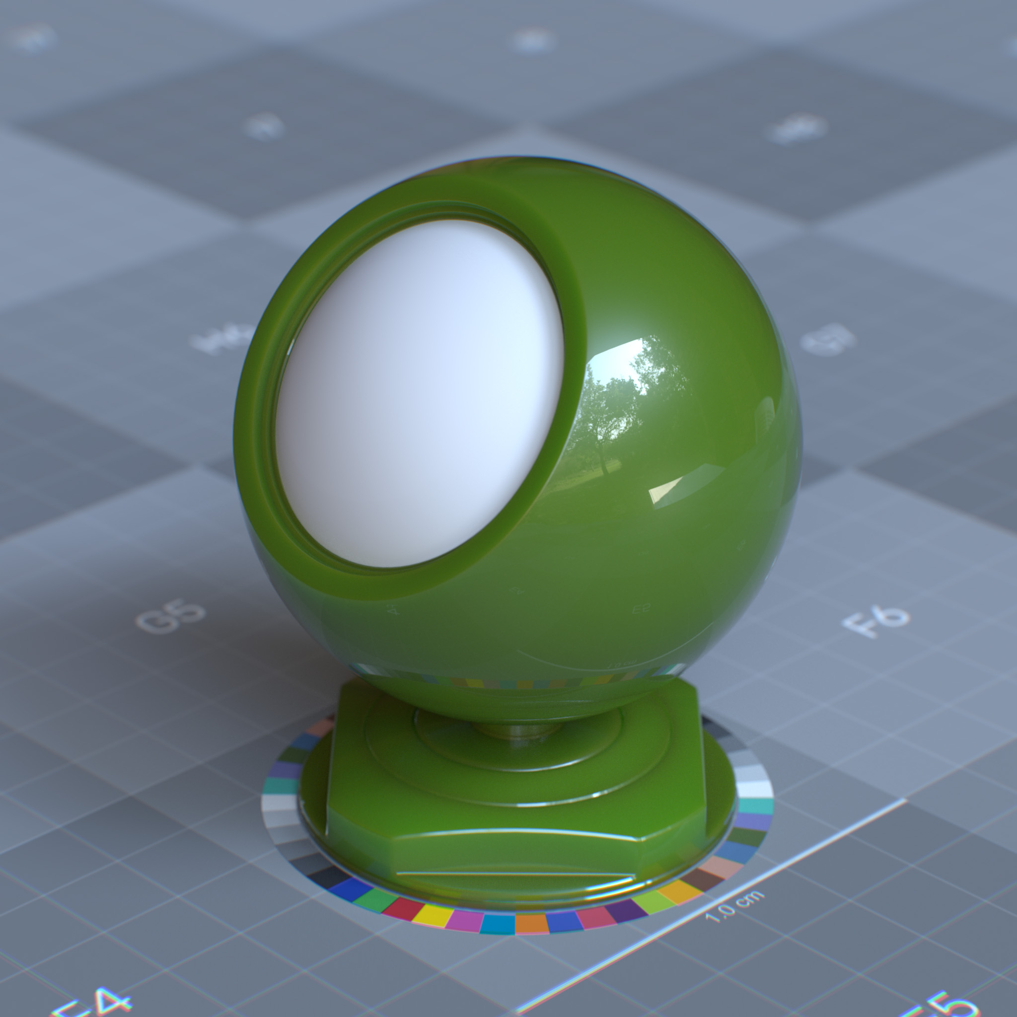
|
Affect Roughness
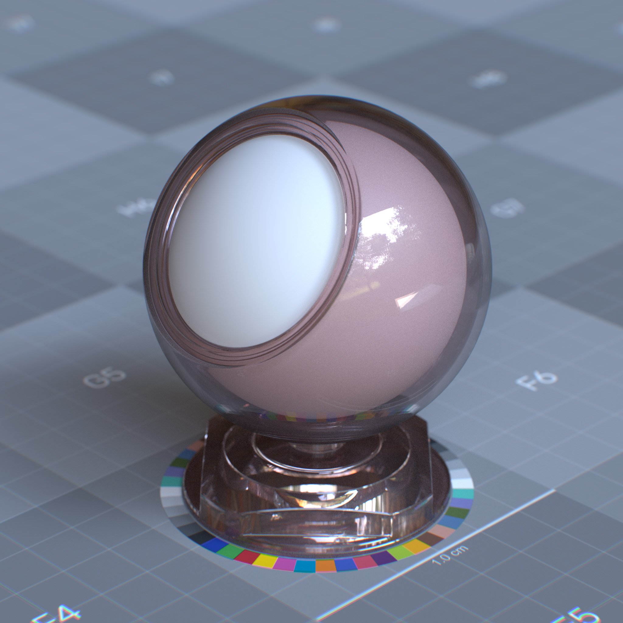
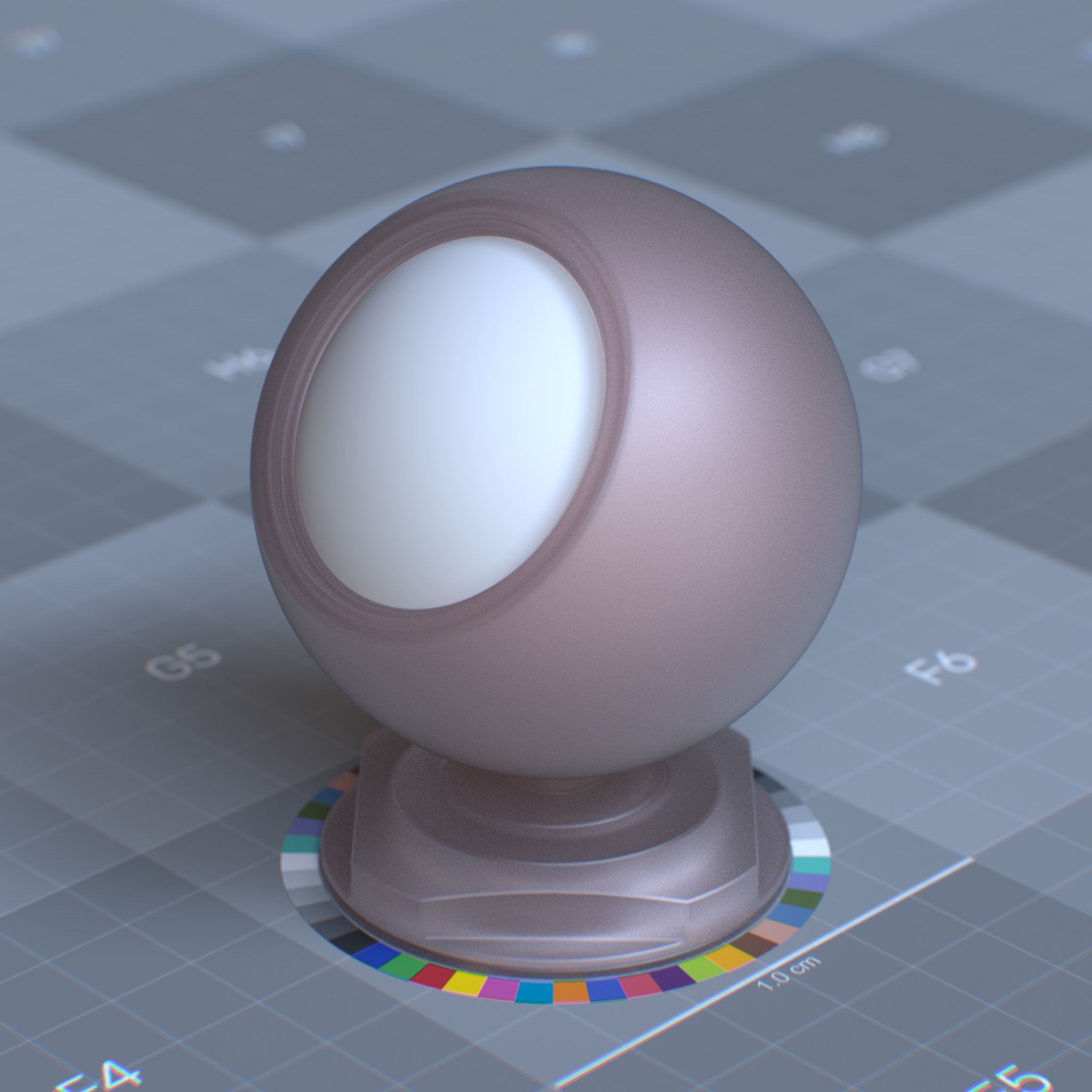
This parameter controls the roughness of the specular reflection, and specular transmission under the coating layer.
In the real world, refracted rays exhibit internal reflection within the coating medium, which can go back down to the underlying surface, which may scatter due to the roughness of the undercoating surface. Affect Roughness can be used to emulate this effect. At 0.0, this parameter has no effects.
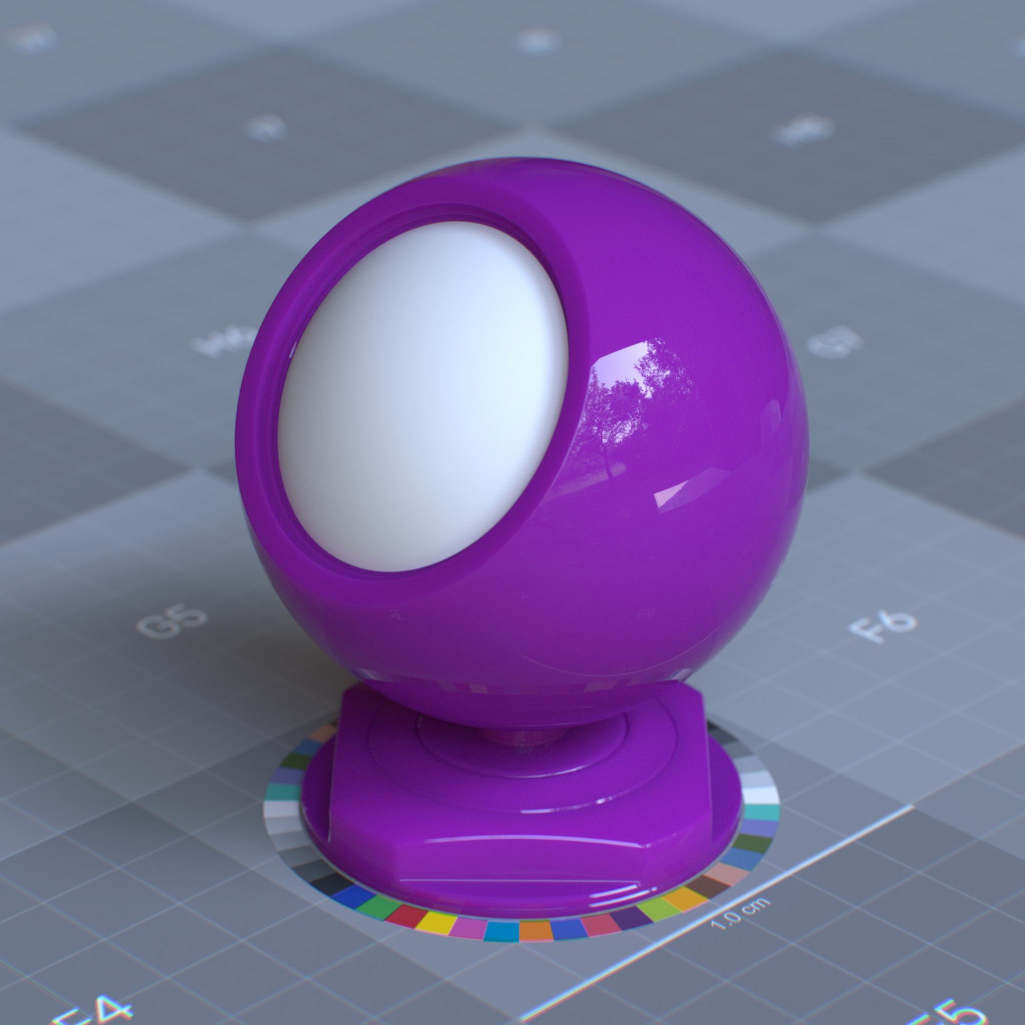
Specular Reflection Weight: 1.0# Specular Reflection Roughness: 0.0 |
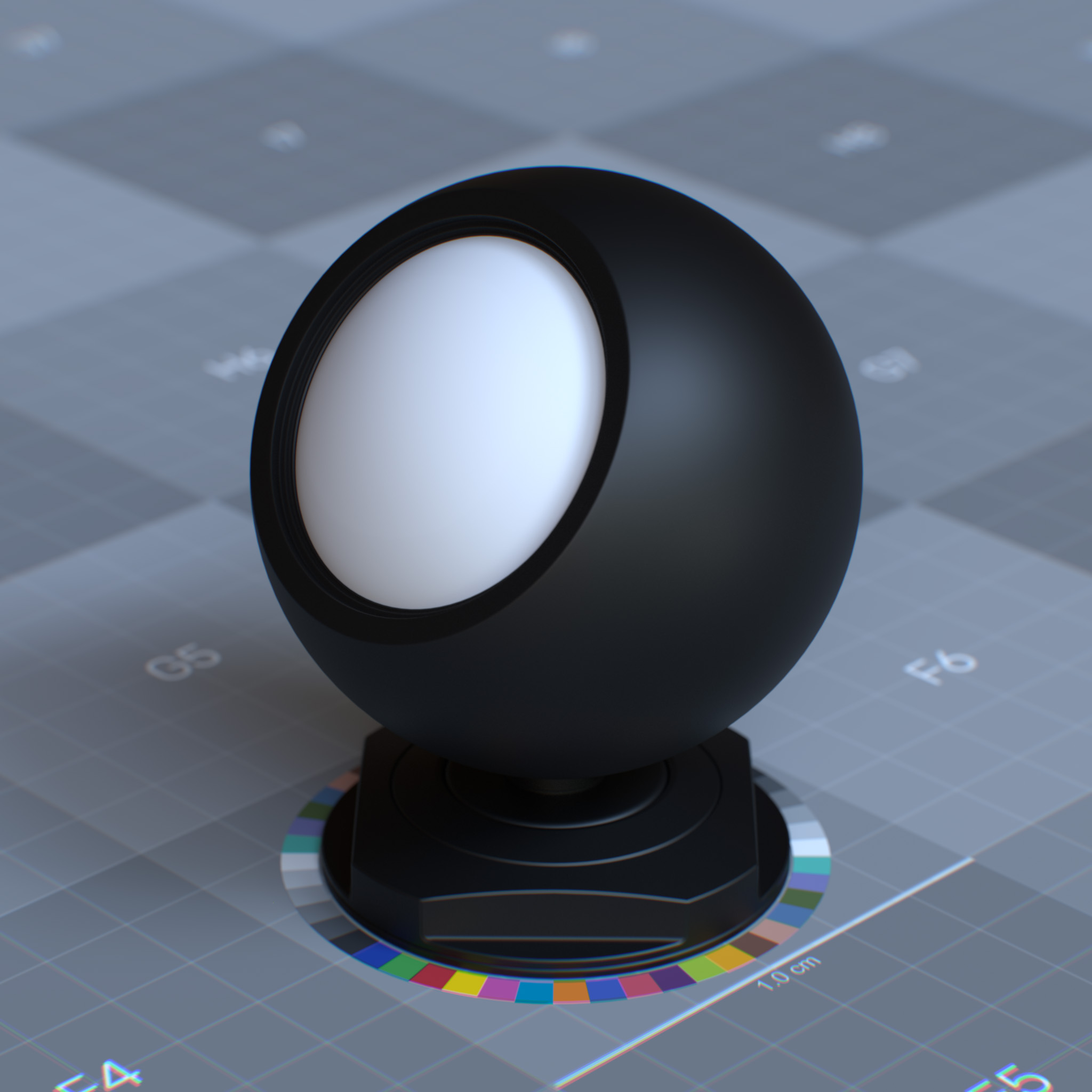
Coat Weight: 1.0# Coat Roughness: 0.5 |
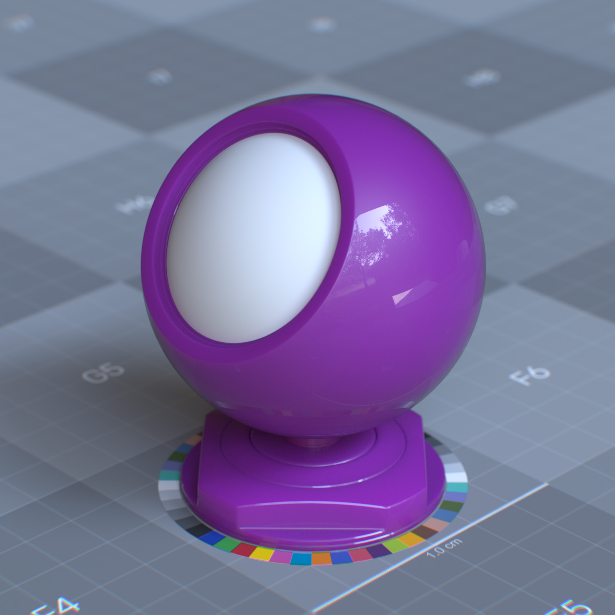
Coat Affect Roughness: 0.0# |
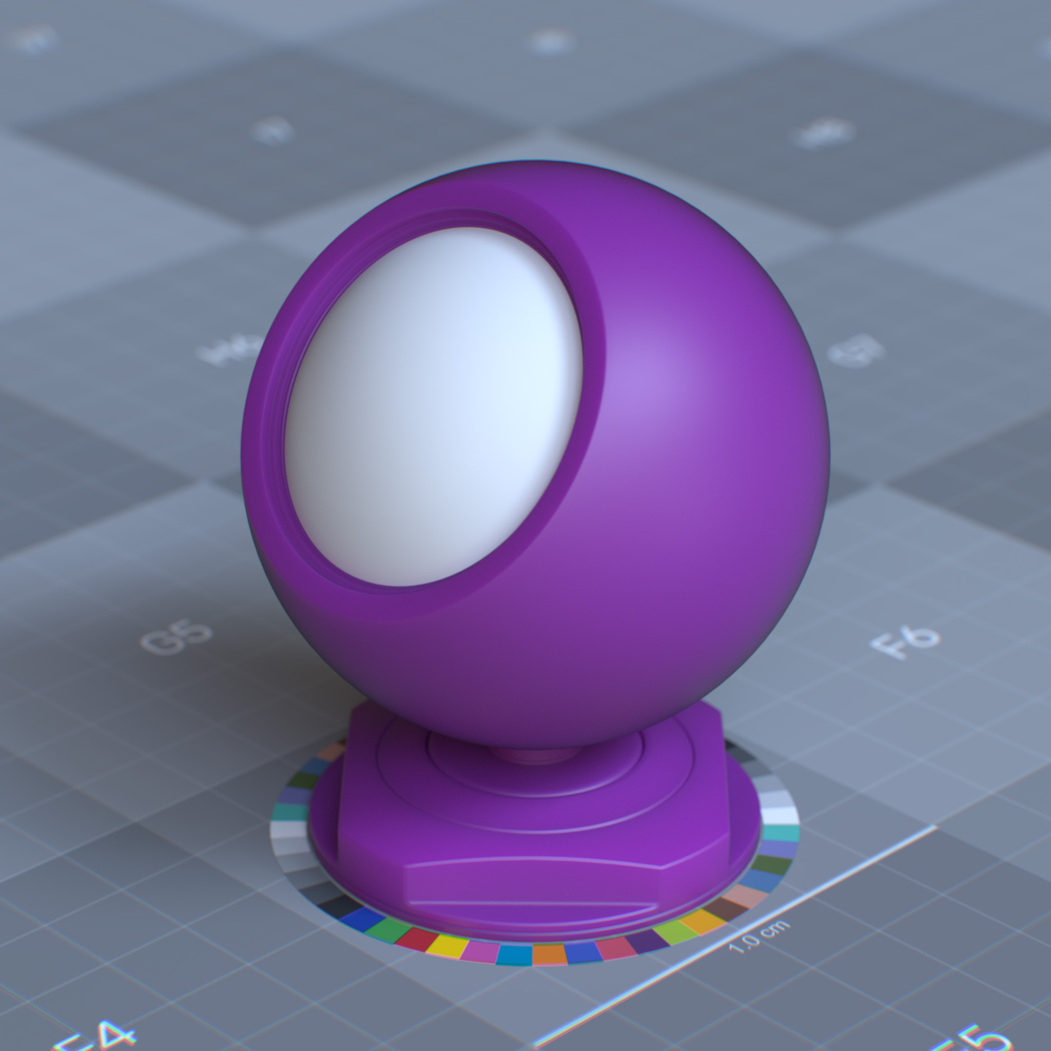
Coat Affect Roughness: 1.0# |
|

|
|
Normal
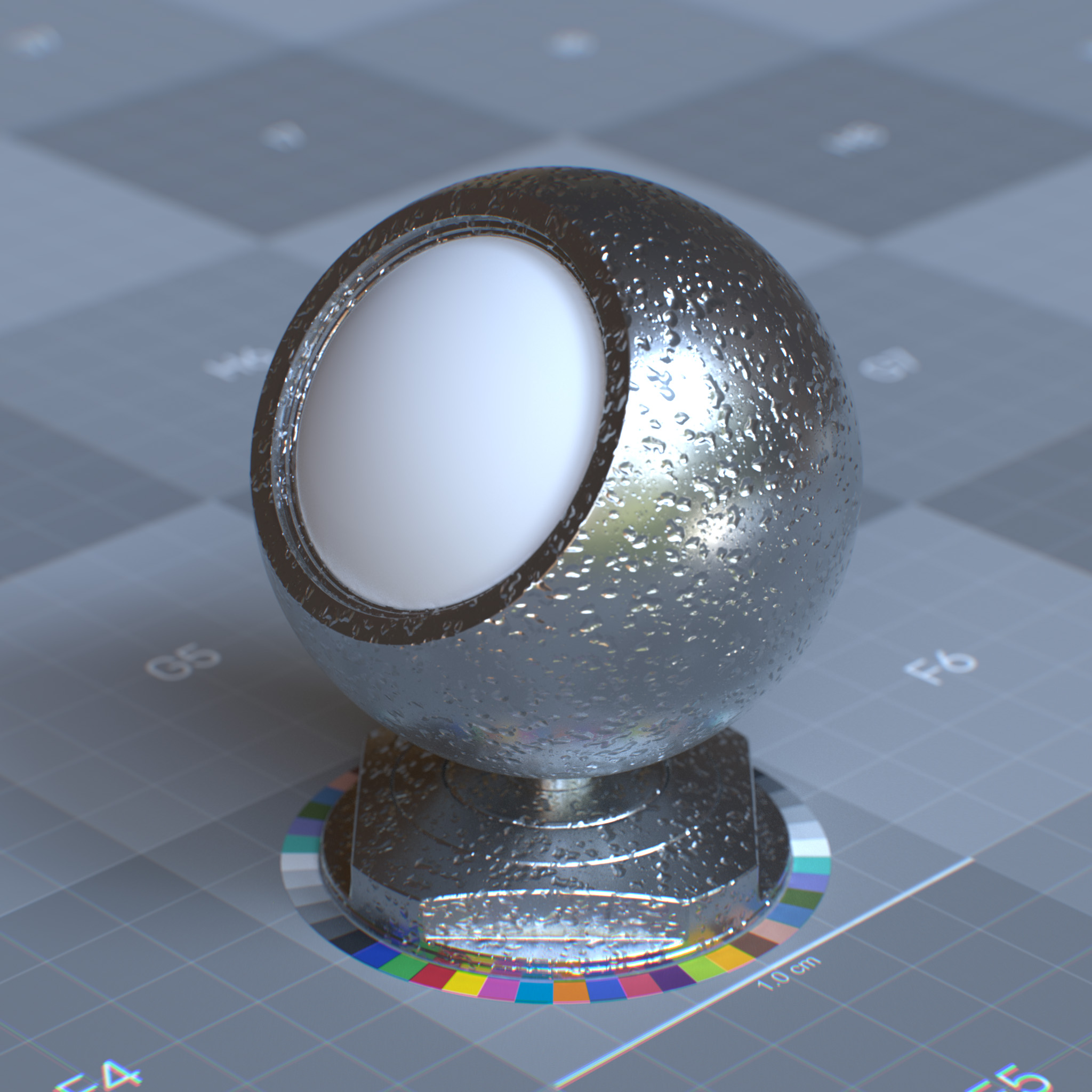
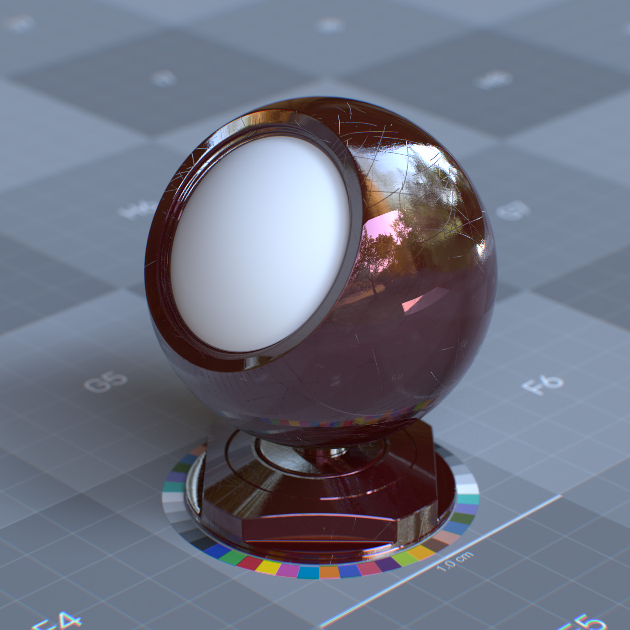
This parameter sets the “normal direction” for the coating layer, which affects the Fresnel blending of the coating layer over the surface. The coat normal can create surface effects like raindrops, imperfections in car paint, or glazing on the food.
Note
The “coat normal” only affects the coating layer and has no effects on the underlying surface normal.
|
|
Sheen
Sheen simulates soft, velvet-like surface reflections common in fabrics and textiles. It adds angle-dependent color and roughness to create microfiber scattering effects typically seen in materials like cloth, carbon fiber, and velvet
Parameters
This layer creates an energy-conserving retro-reflective sheen BRDF. Sheen simulates surface micro-fibers, with axes oriented parallel to the surface normal, creating specular highlights at grazing angles.
Sheen can create soft backscattering materials like fine powder, dust, satin, leaf, and peach fuzz on the skin.
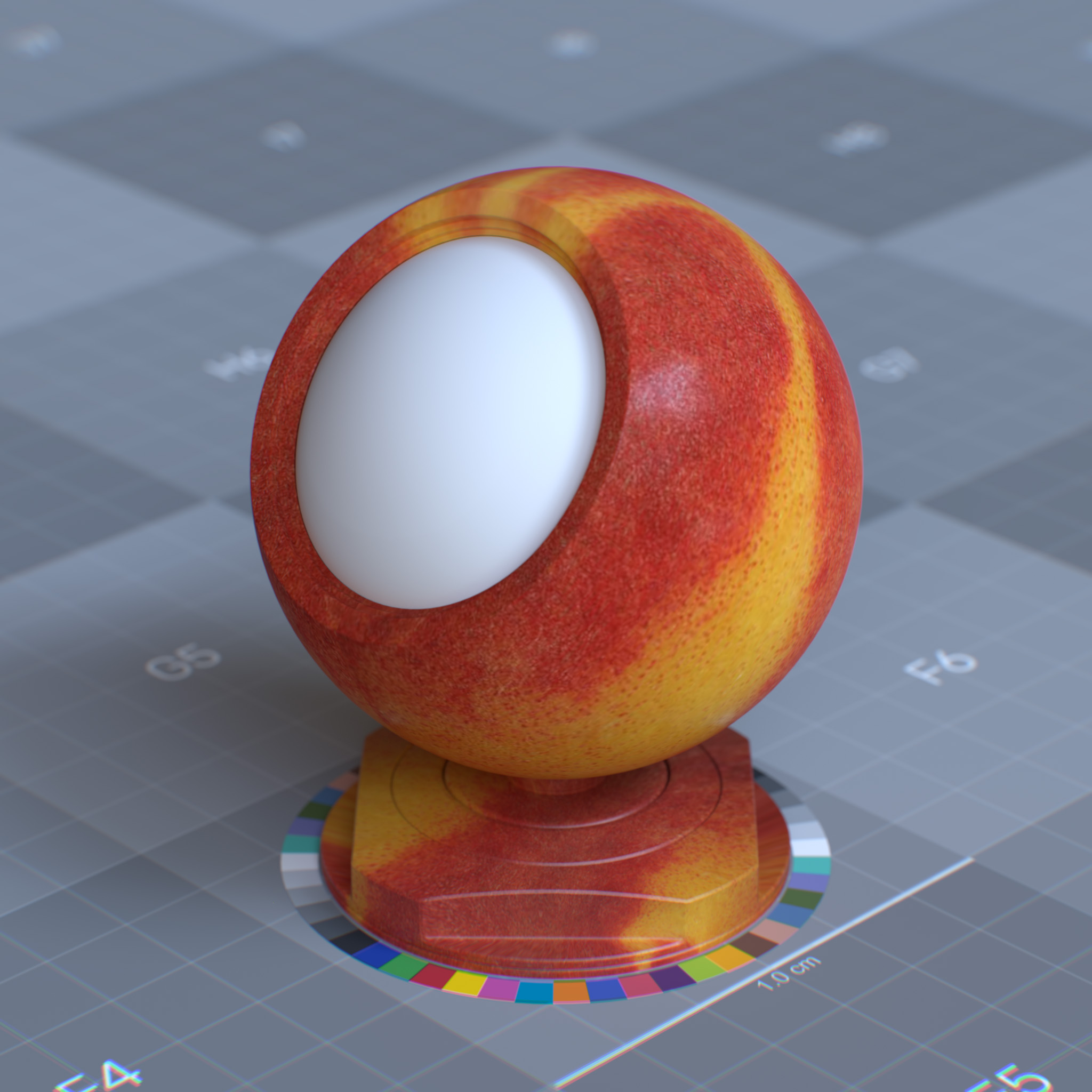
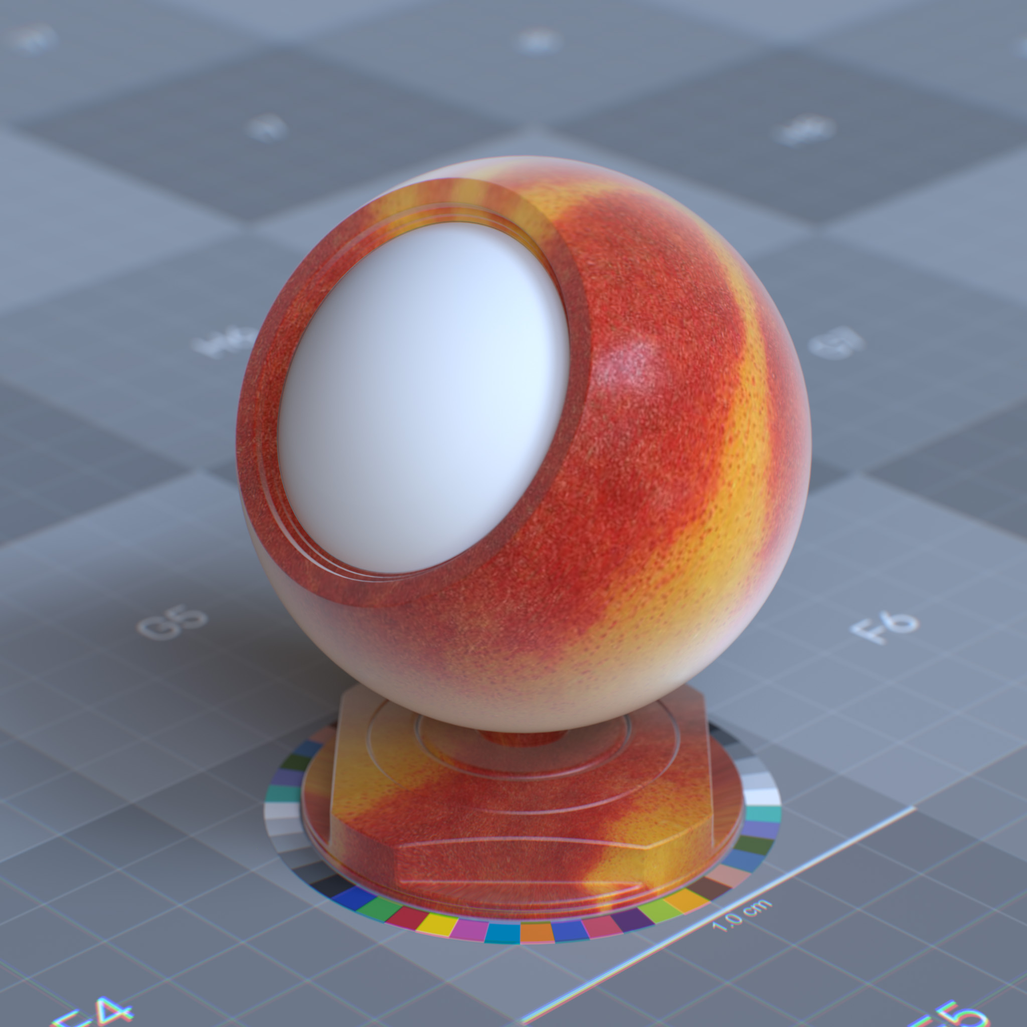
Weight
This parameter sets the density and length of micro-fibers. At 0.0, sheen has no effects.
|
|
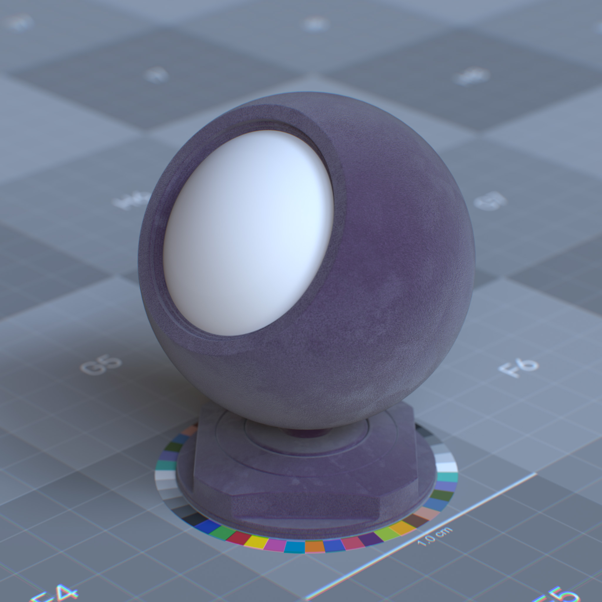
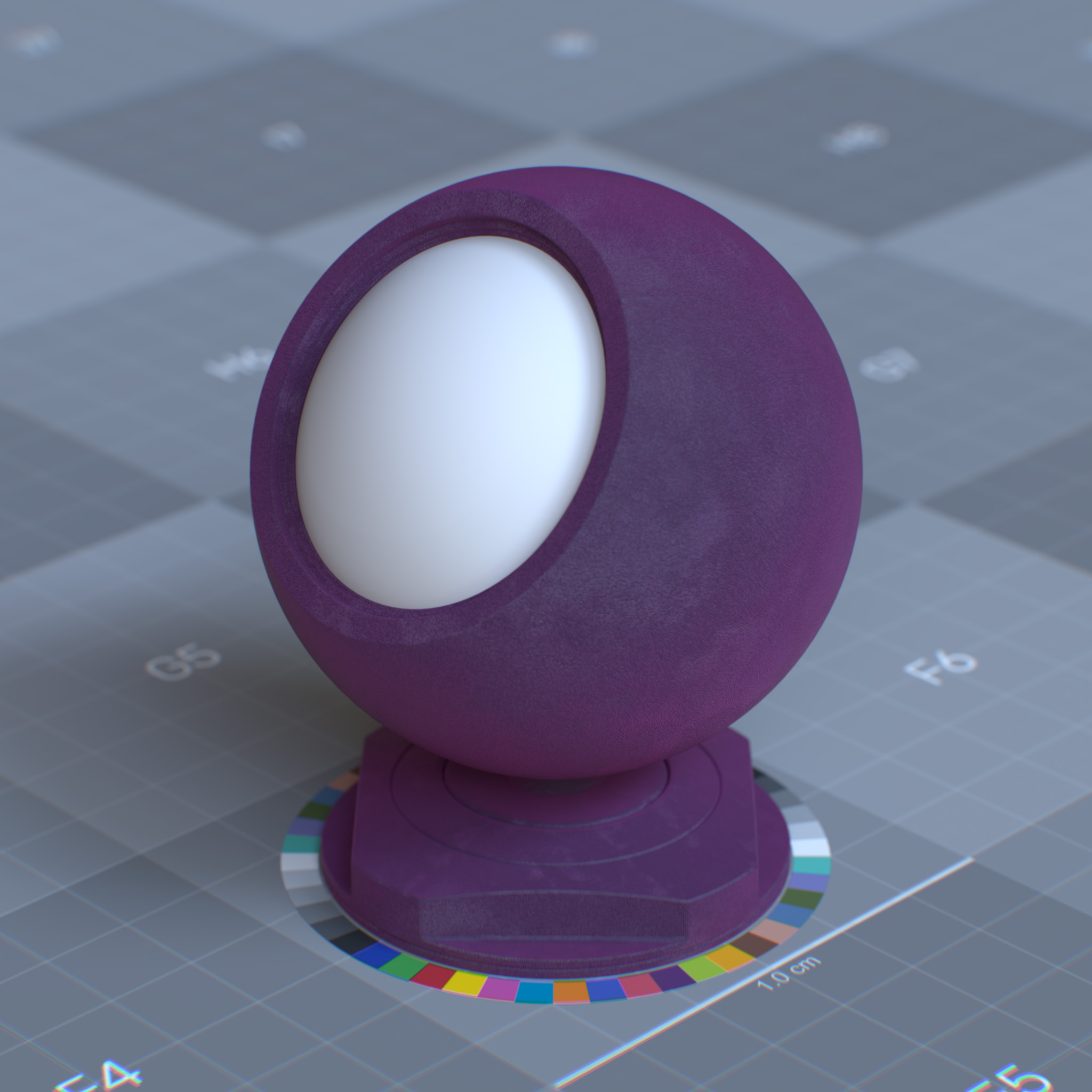
Color
This parameter tints the color of the sheen, i.e., micro-fibers.
|
|
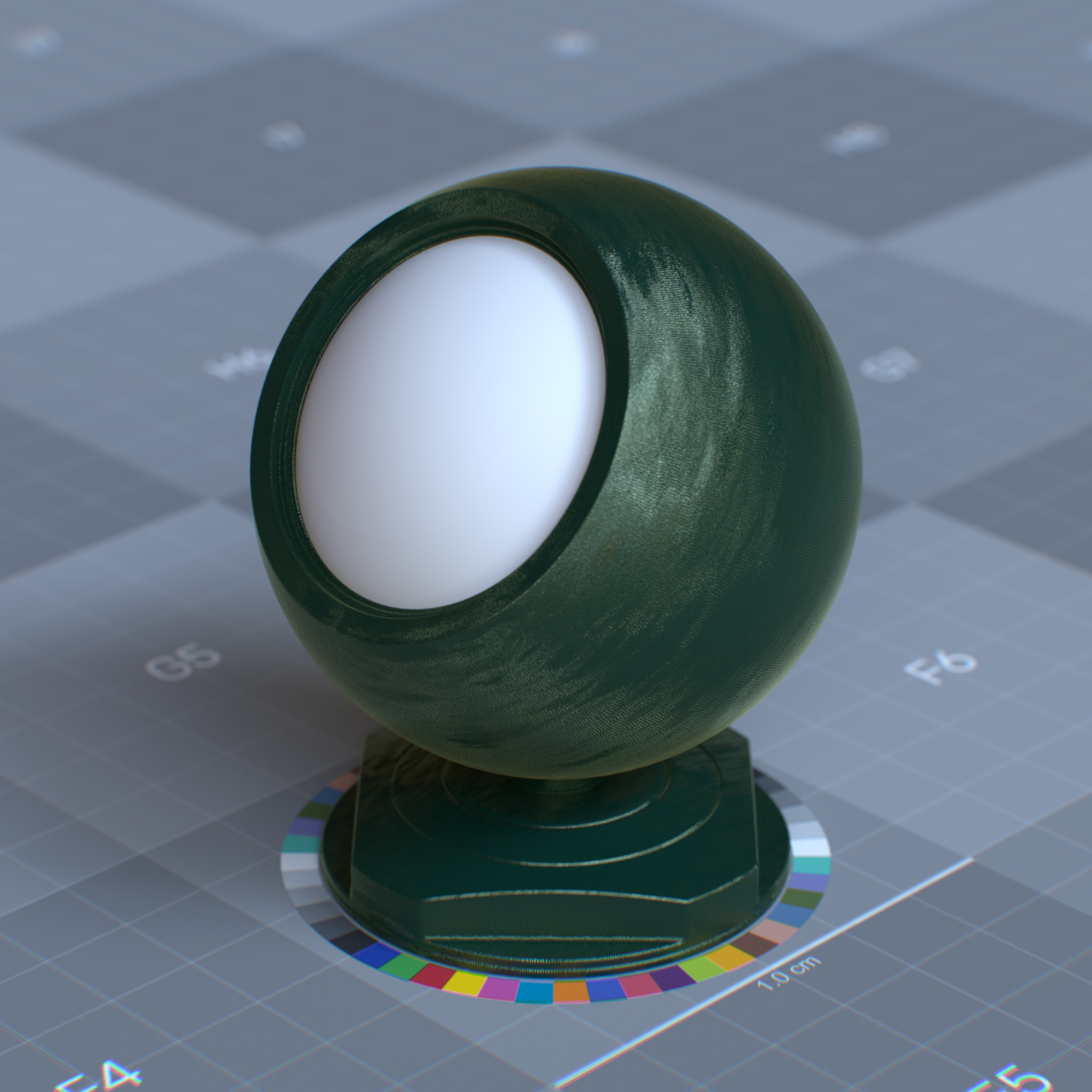
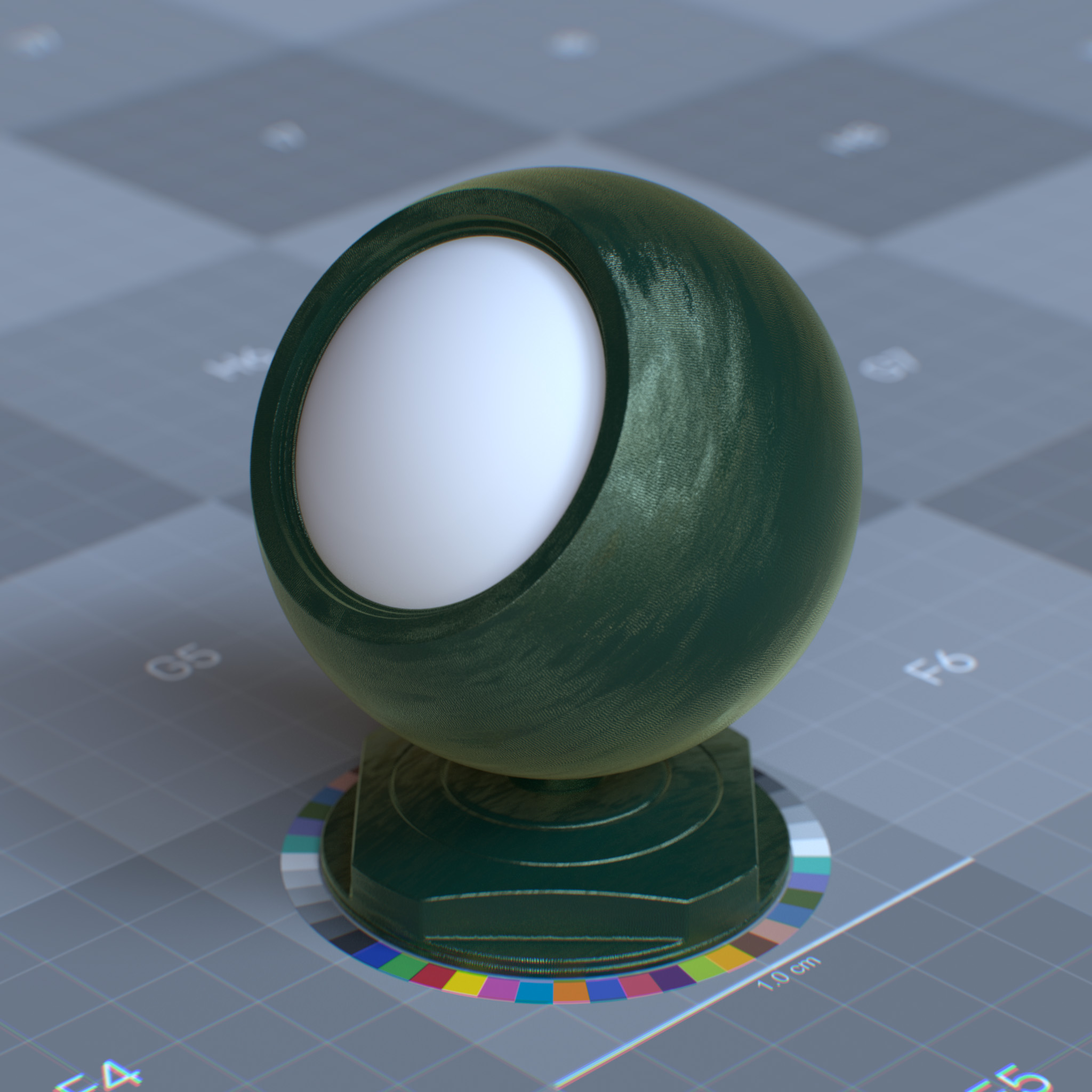
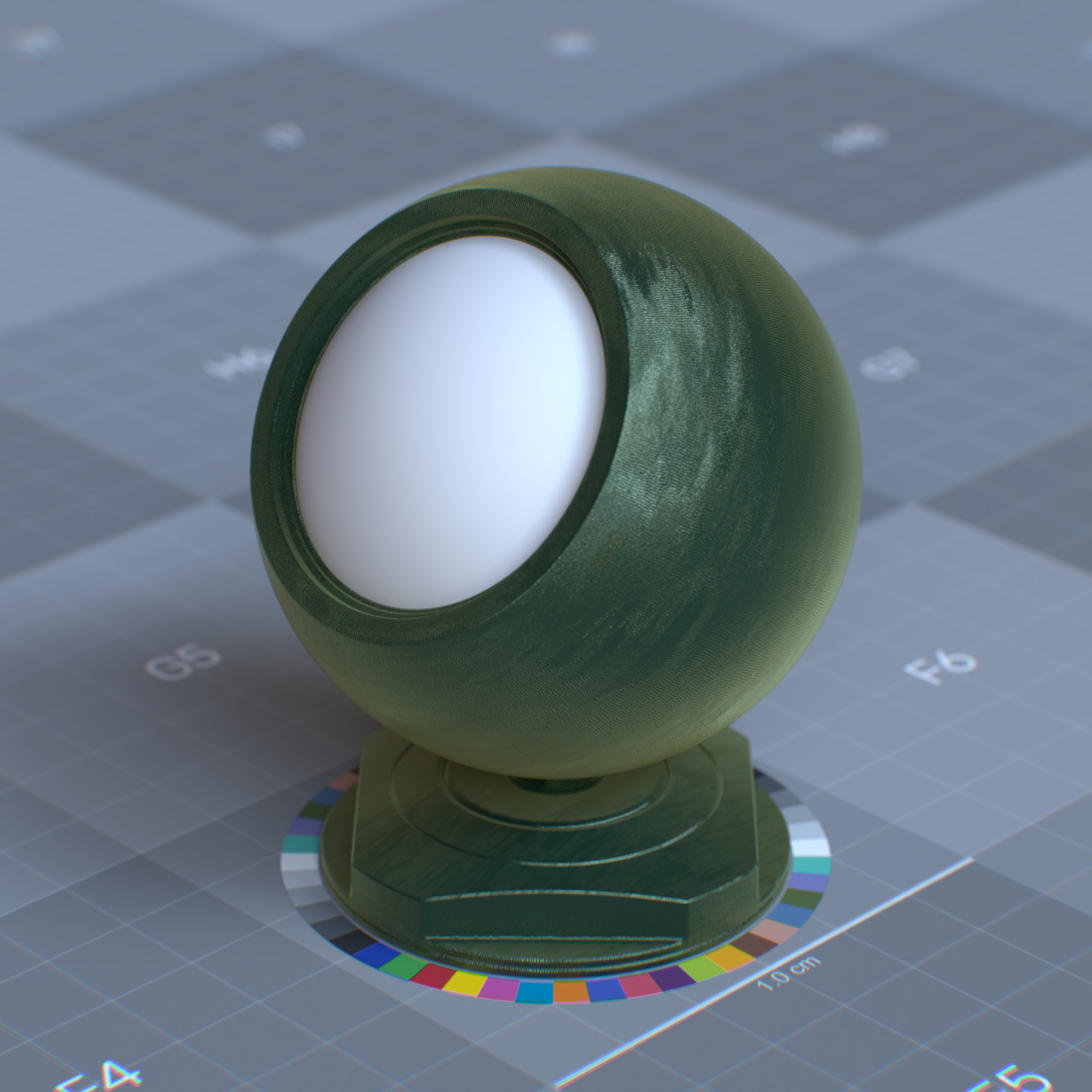
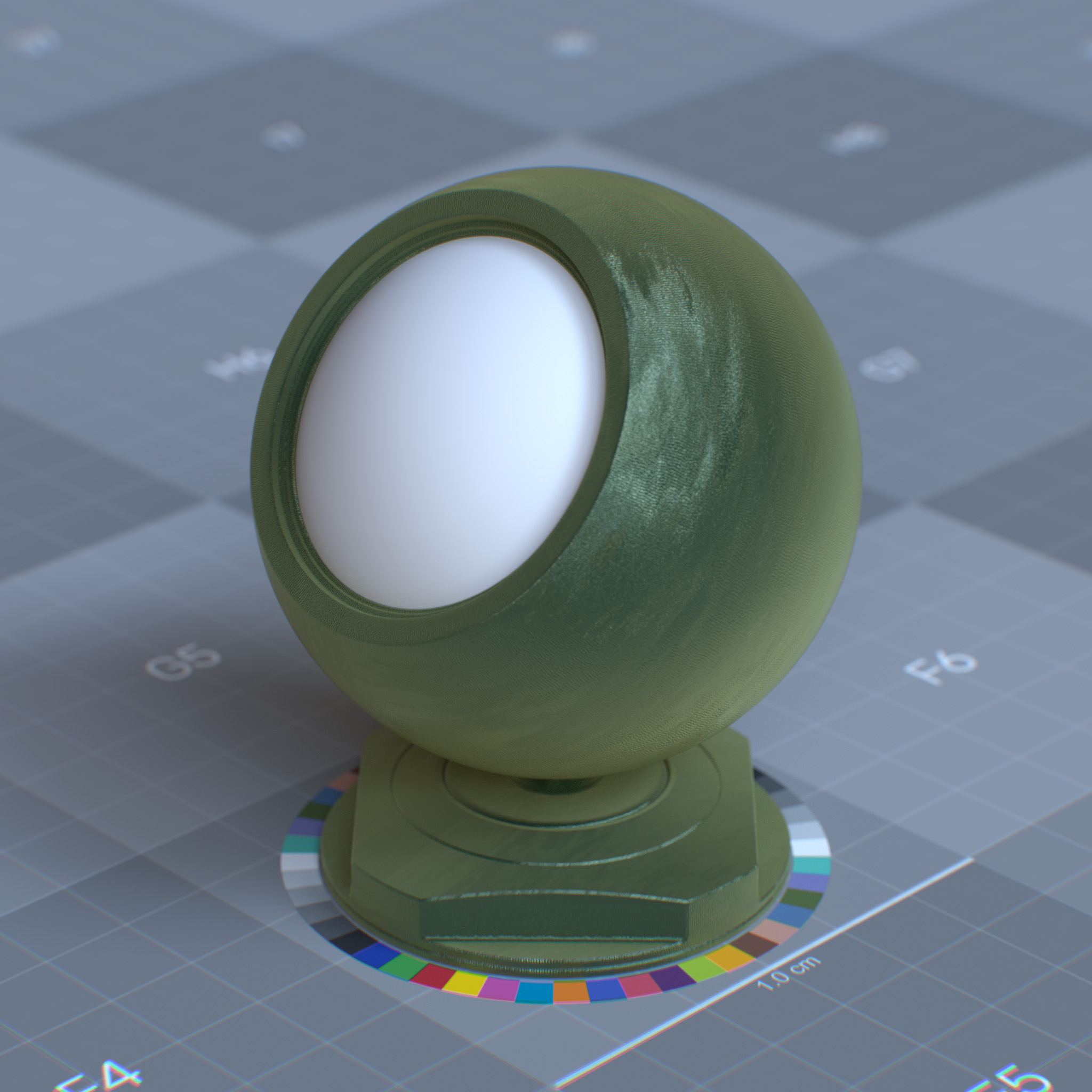
Roughness
This parameter sets the sheen effect roughness. Micro-fibers diverge more from the “surface normal” direction at a higher value, resulting in a softer look.
|
|
|
|
Thin Film
Thin film simulates iridescent interference effects caused by microscopically thin transparent layers, as seen in soap bubbles, oil slicks, and some insect wings. The effect varies by viewing angle and film thickness, creating rainbow-like color shifts across the surface.
Parameters
Display Name |
Name |
Type |
Default |
|---|---|---|---|
enable_thin_film |
bool |
false |
|
thin_film_thickness |
float |
400.0 |
|
thin_film_ior_preset |
enum |
ior_custom |
|
thin_film_ior |
float |
1.52 |
This layer models a reflective thin film when a metal and or specular reflection layer presents. Due to interference, a view-dependent iridescence effect occurs when the thin film layer thickness is close to the visible spectrum.
It can create materials like a peacock feather, burnt metal, soap bubble, and car paint.
Enable Thin Film
Enables thin film layer
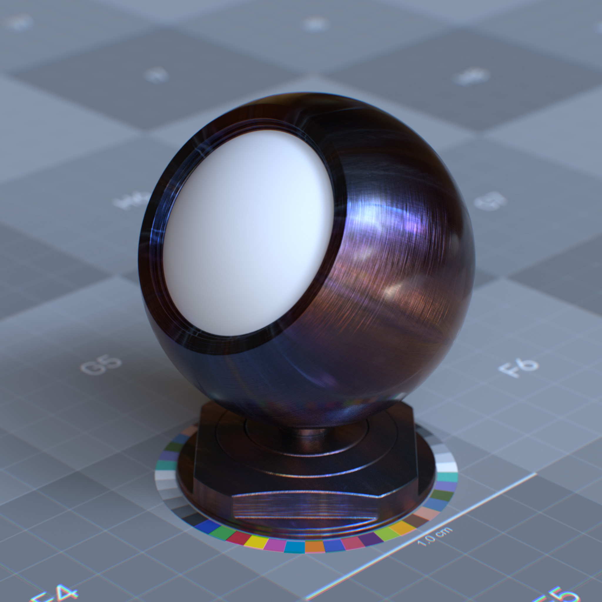
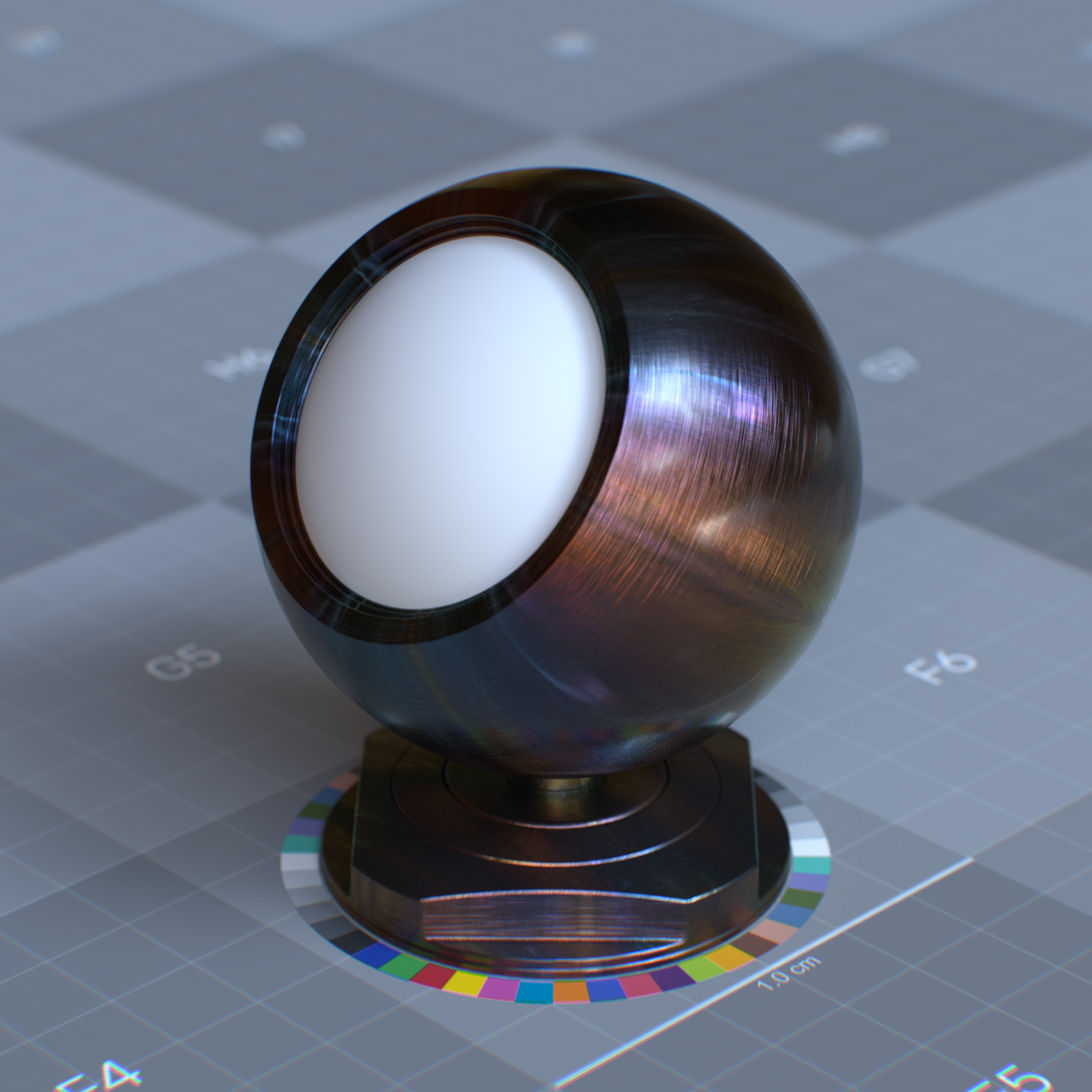
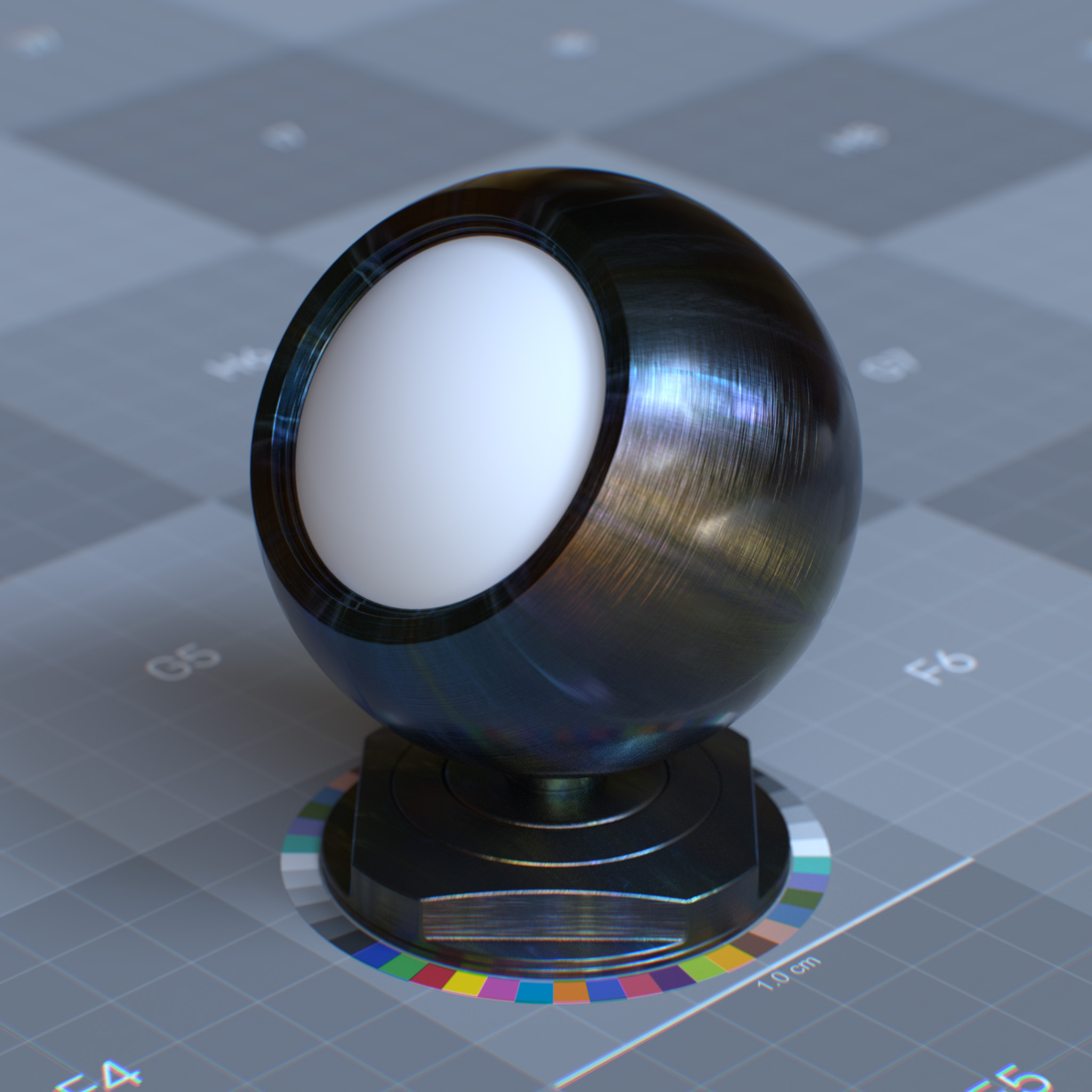
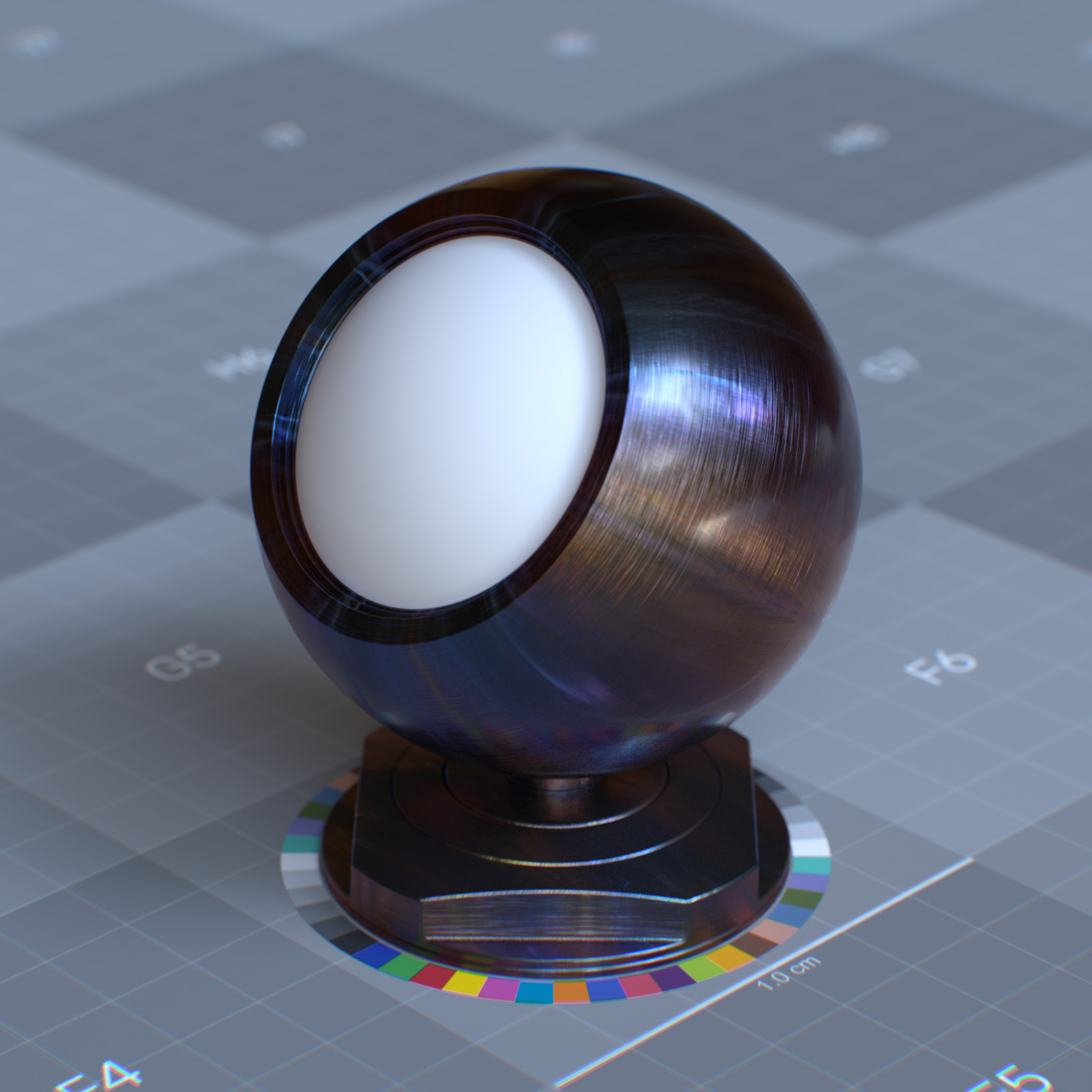
Thickness (nm)
This parameter sets the thickness of the thin film layer in nanometers. At 0.0, the iridescence effect is disabled.
Tip
A typical soap bubble thickness is about 250 - 600 nanometers. By contrast, human hair thickness is in the range of 40,000 - 100,000 nanometers wide.
|
|
|
|
IOR Preset
This parameter presents a list of known IORs (index of refractions) for various materials, including glass, soap bubble, diamond. One can use custom IOR by setting this parameter to ior_custom and a value for the specular reflection’s IOR parameter.
IOR
This parameter sets the refractive index of the thin film layer.
Tip
The refractive index of water is 1.33, and a typical soap is 1.5. For a realistic result, the refractive index of the thin film should be less than soap and greater than water, i.e., 1.34 - 1.49.
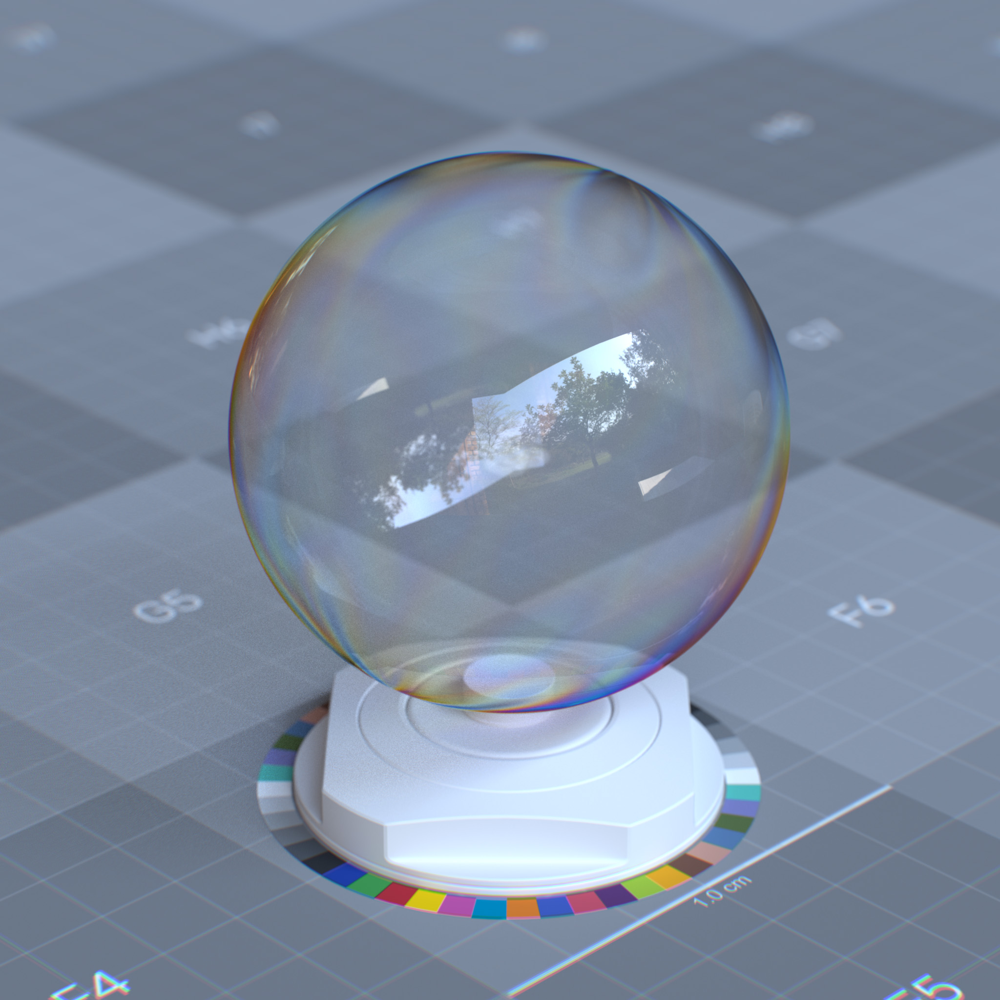
|
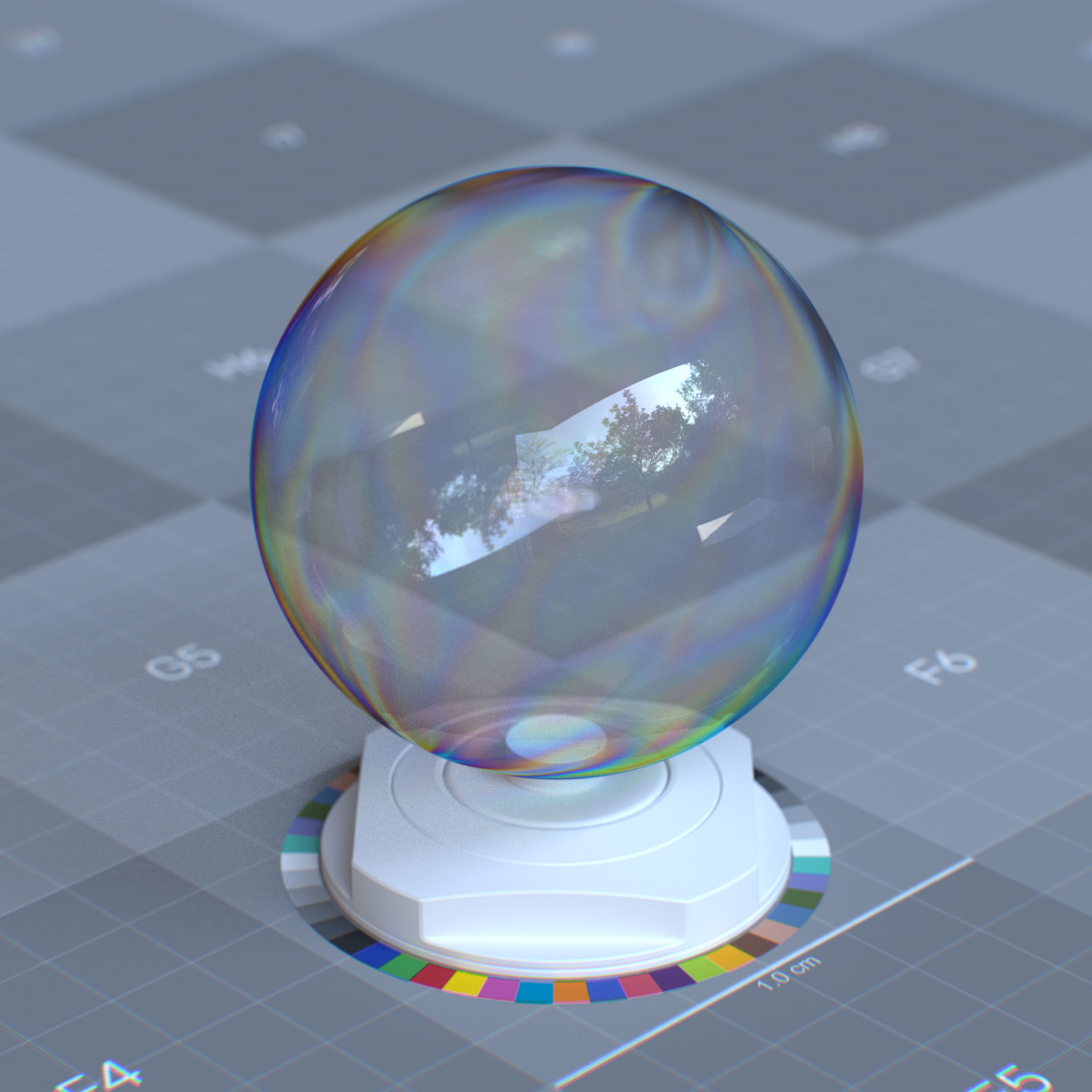
|
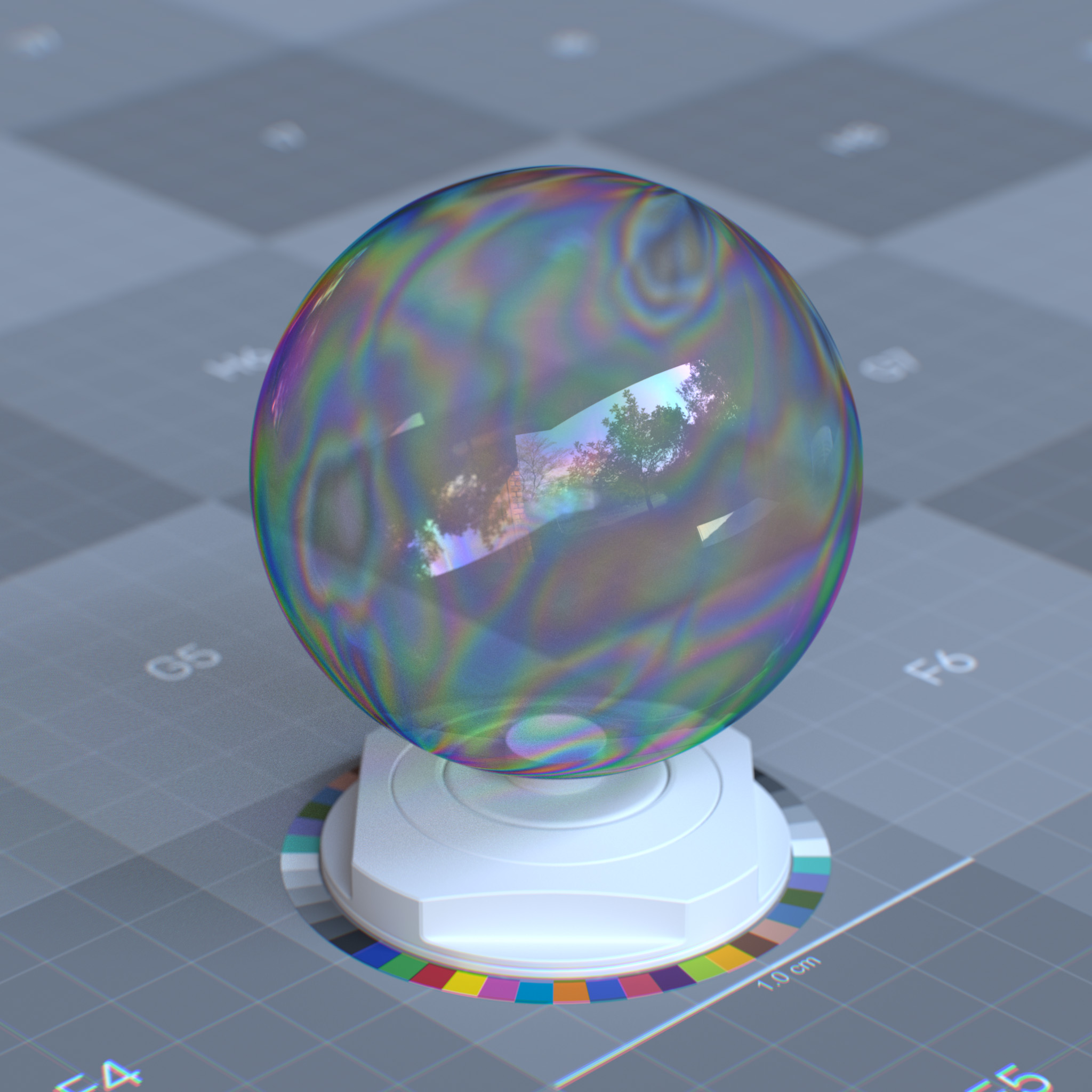
|
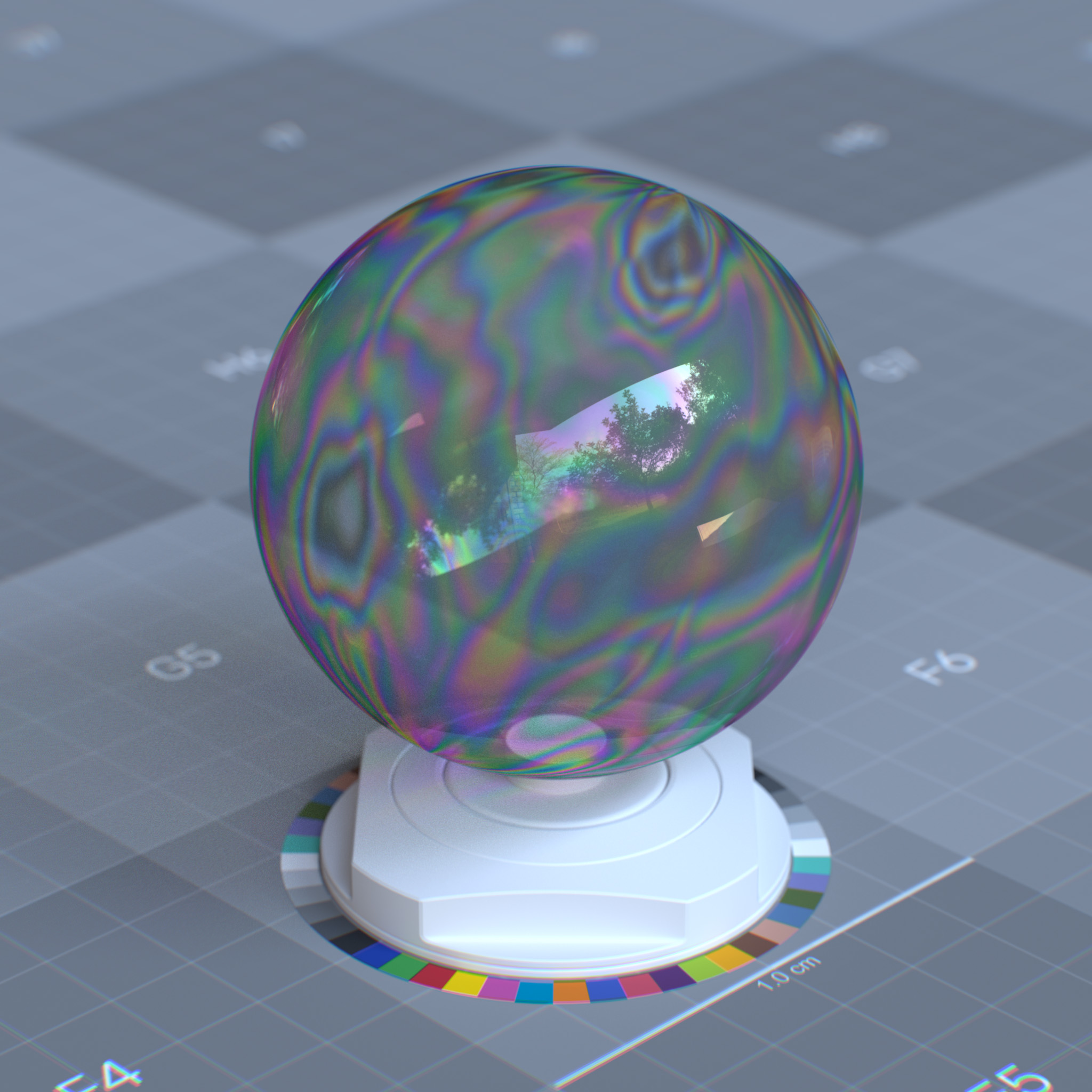
|
Emission
Emissivity defines how much light a surface emits independently of received light. This parameter creates self-illuminating effects like neon signs, screens, or bioluminescence materials. Emissivity maintains physical accuracy by contributing to scene lighting and global illumination calculations.
Parameters
Display Name |
Name |
Type |
Default |
|---|---|---|---|
Weight |
emission_weight |
float |
0.0 |
Emission Mode |
emission_mode |
enum |
emission_lx |
intensity |
emission_intensity |
float |
1.0 |
Color |
emission_color |
color |
1.0, 1.0, 1.0 |
Use Temperature |
emission_use_temperature |
bool |
false |
Temperature |
emission_temperature |
float |
6500.0 |
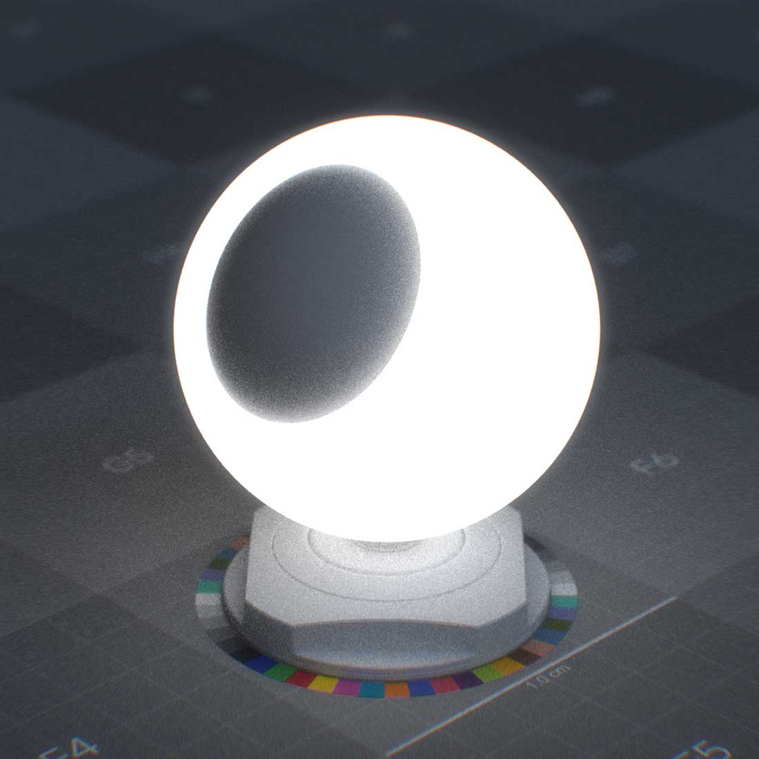
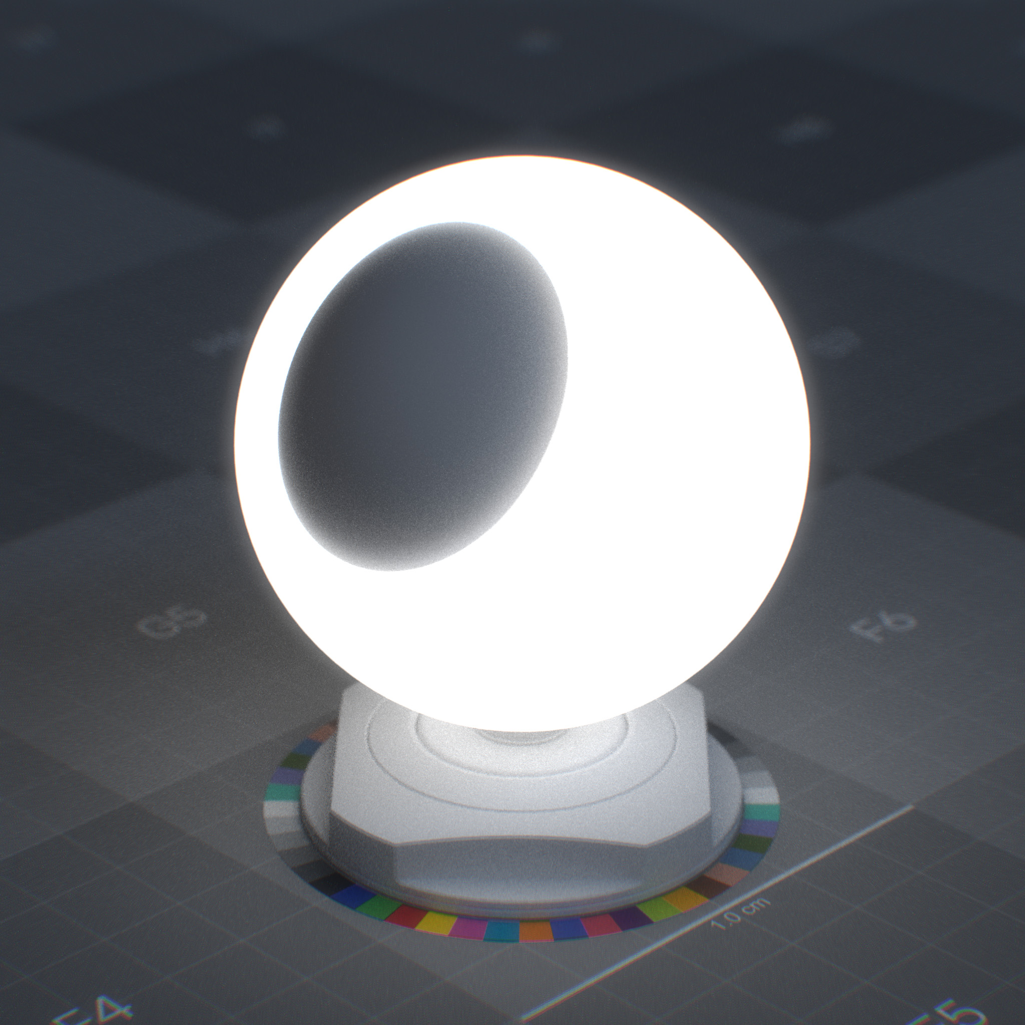
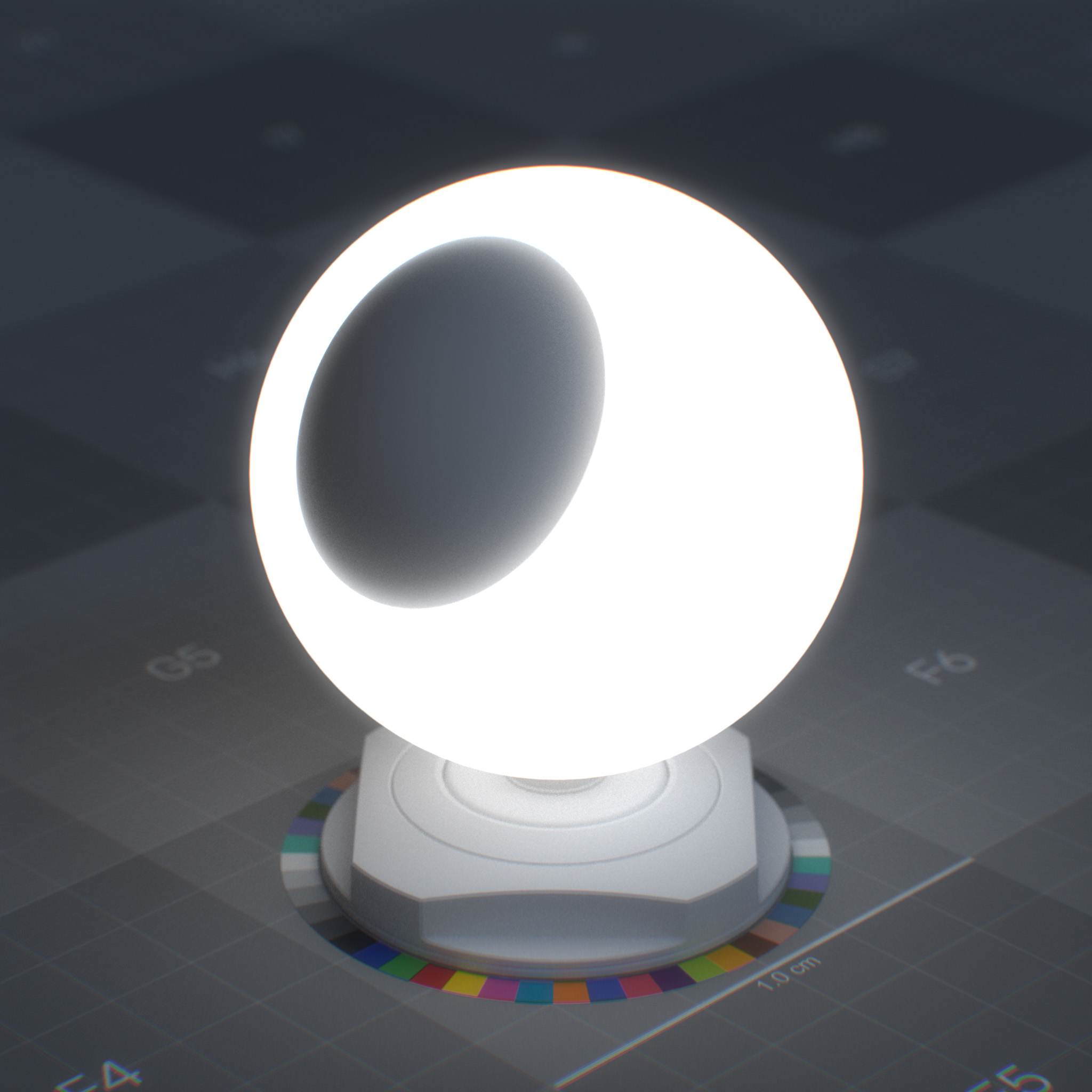
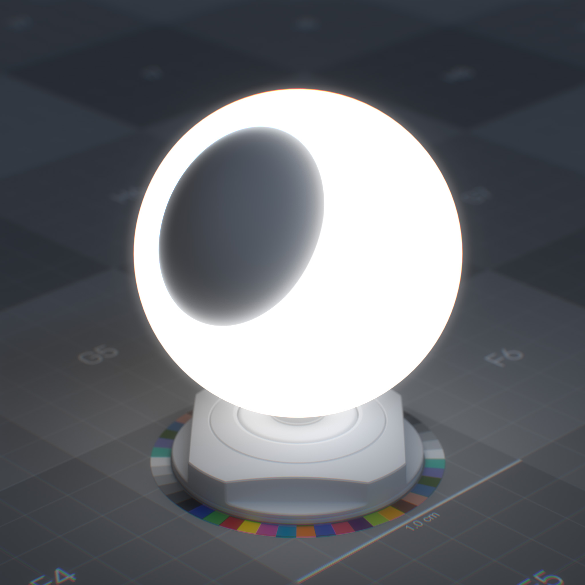
This layer adds directionally uniform EDF under the coating layer, which describes the light-emitting properties of the surface.
It can create materials like an incandescent light-bulb, glowing lava, and LED panel.
Note
In the RTX – Interactive (Path Tracing) mode, to reduce the noise in the indirectly lit area using emissive materials, one may need to increase the Total Samples per Pixel.
Please see RTX Interactive (Path Tracing) mode render settings for more information.
|
|
|
|
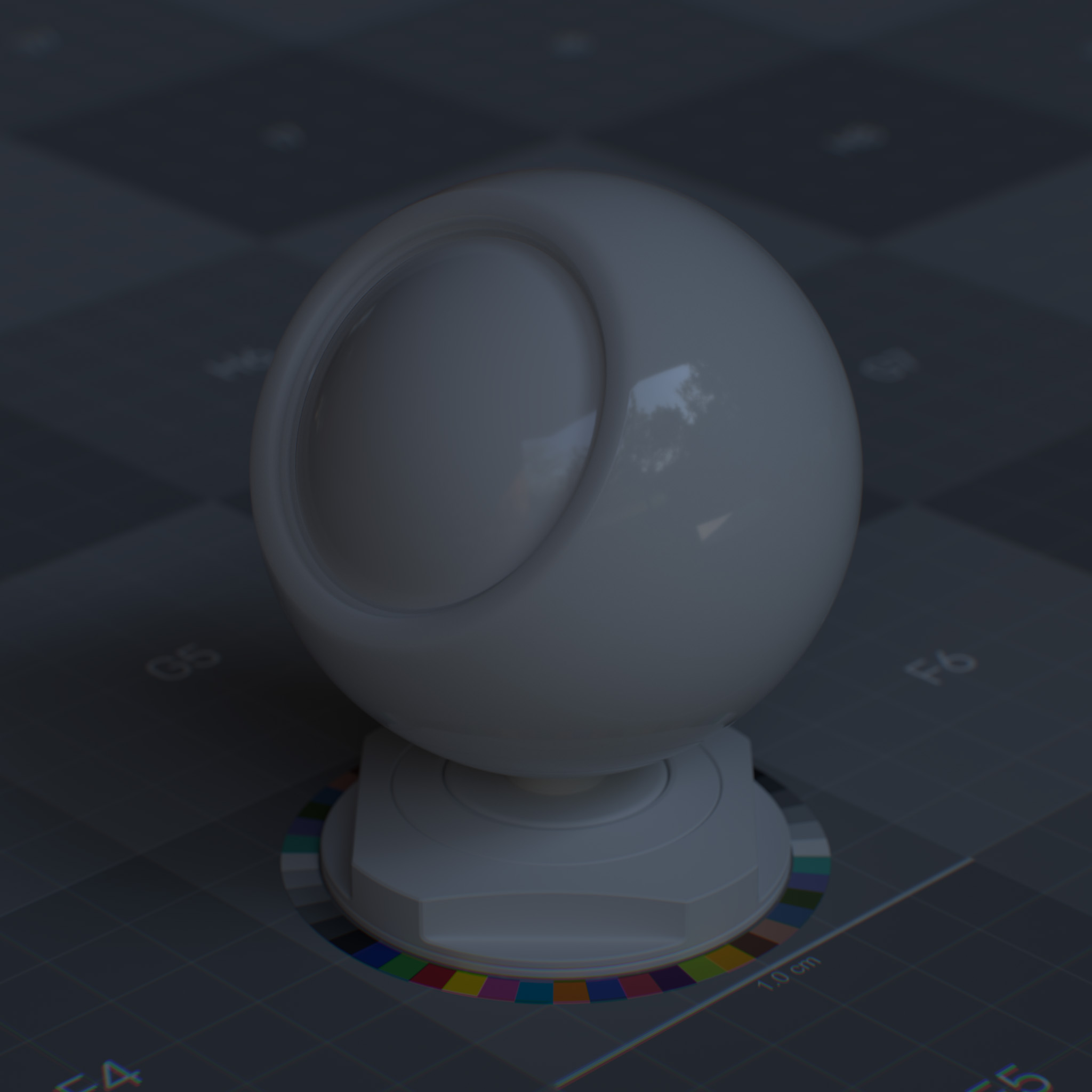
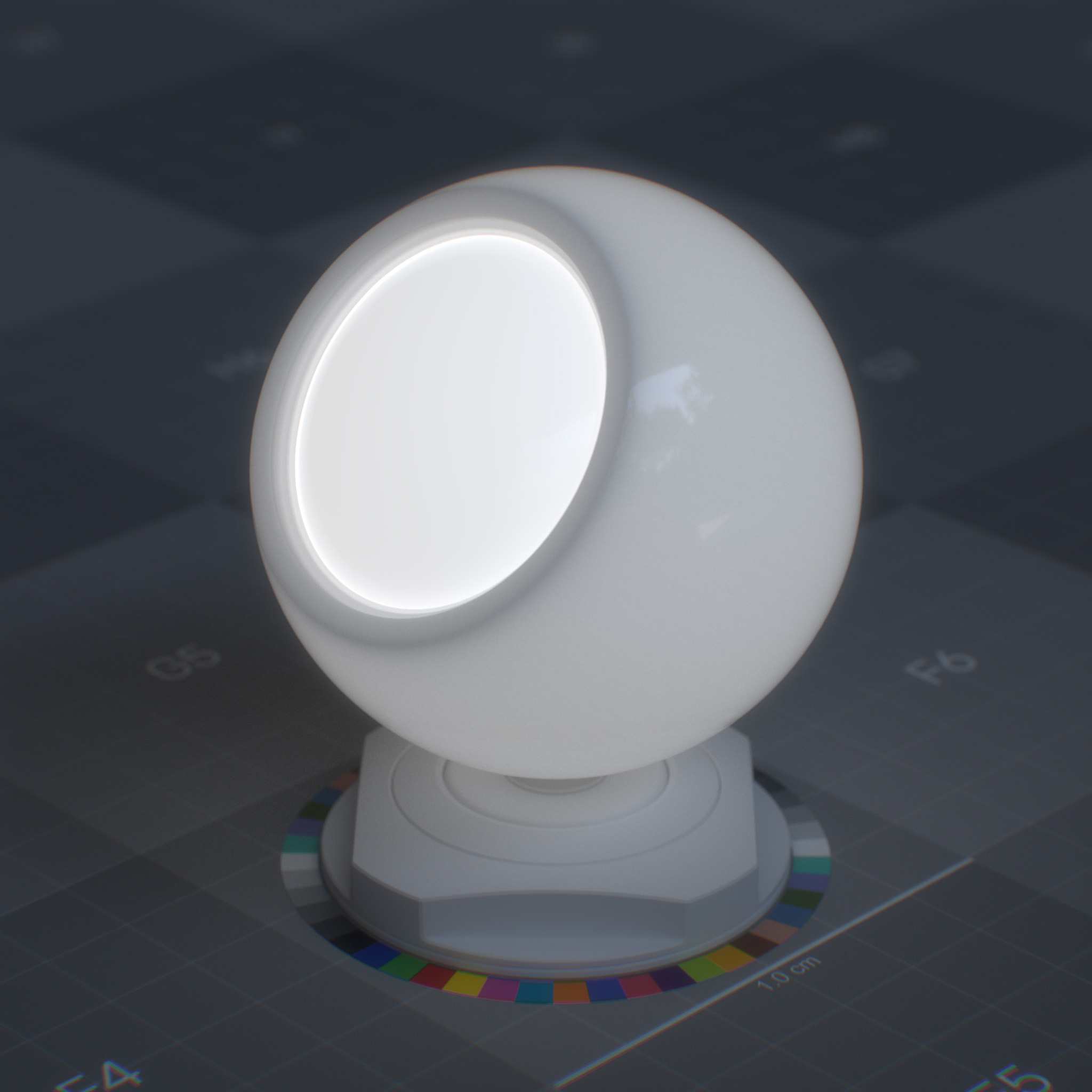
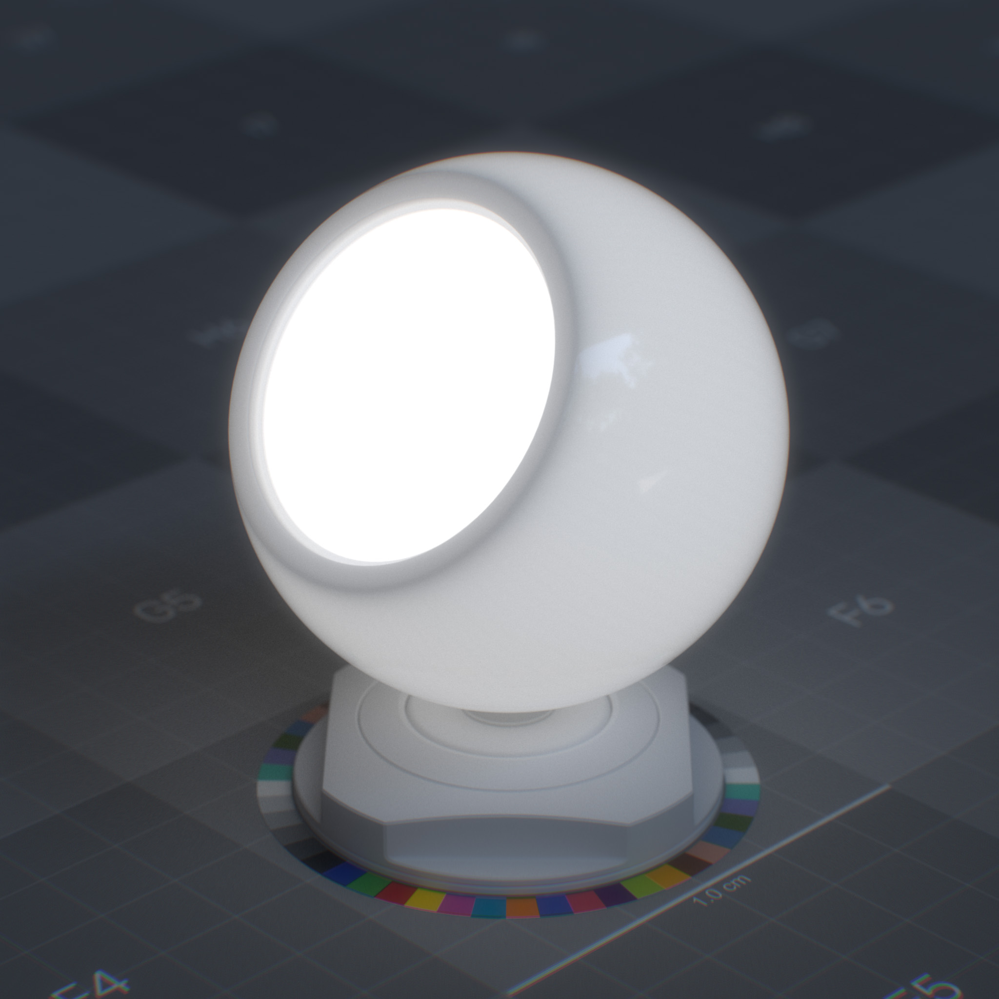
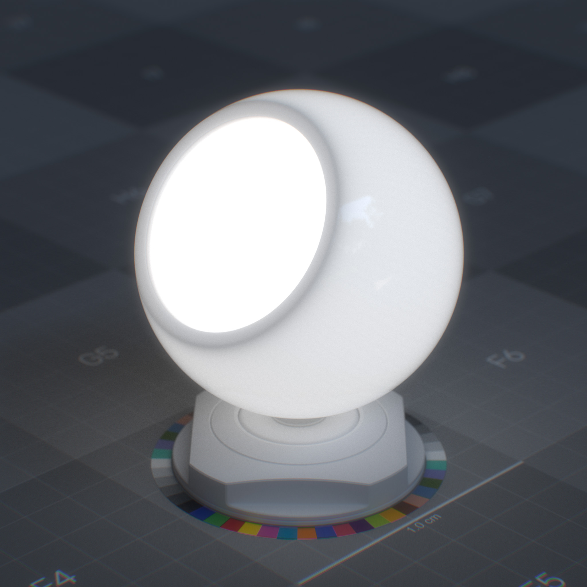
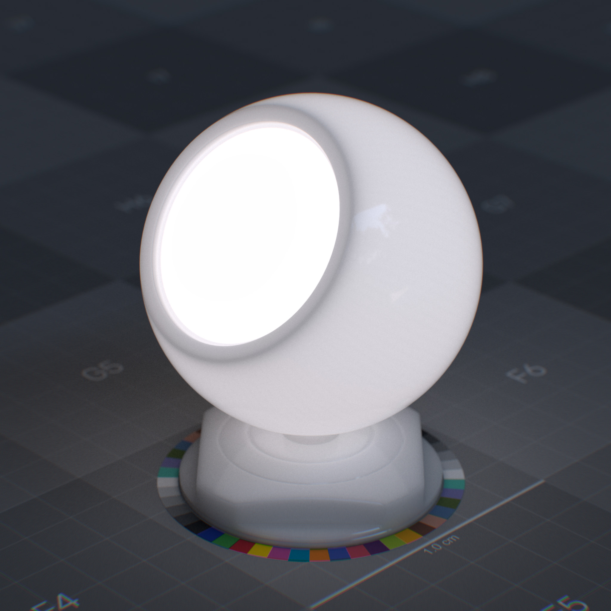
Weight
This parameter sets the amount of light emission from the surface.
|
|
|
|
Emission Mode
This parameter specifies the physical units to use for the emission intensity.
1. “Nit” is the unit of luminance and describes the surface power of a visible light source. The overall illumination of the scene changes depends on the size of the light source.
One nit is equal to one candela per square meter. 1 nit = 1 cd/m^2
The candela per square meter is the base unit of luminance. Candela is the base unit for luminous intensity.
A light source that emits one candela of luminous intensity onto an area of one square meter has a luminance of one candela per square meter or one nit. As an example, a calibrated monitor has a brightness of 120 cd/m^2 or 120 nits.
2. “Lux” is the unit of illuminance and describes the total amount of visible light that a light source emits. The overall illumination of the scene does not change depending on the size of the light source.
One lux is equal to one lumen per square meter. 1 lux = 1 lm/m^2
A light source that emits one candela of luminous intensity from an area of one steradian has a luminous flux of one lumen.
A light source that emits one lumen of luminous flux onto an area of one square meter has an illuminance of one lux. As an example, very bright sunlight has a brightness of 120,000 lux.
Intensity
This parameter sets the emission intensity. The emission mode parameter sets the physical unit for this parameter.
A few examples of illuminance under various lighting conditions:
Lighting Condition |
Illuminance (lx) |
|---|---|
Sunlight |
100,000 - 120,000 |
Daylight |
10,000 - 25,000 |
Overcast |
1000 |
Twilight |
10 |
Full moon |
0.05 – 0.3 |
Ceiling lamp |
400 - 800 |
Table lamp |
200 - 300 |
Candle light |
12.57 |
Color
This parameter sets the emission color.
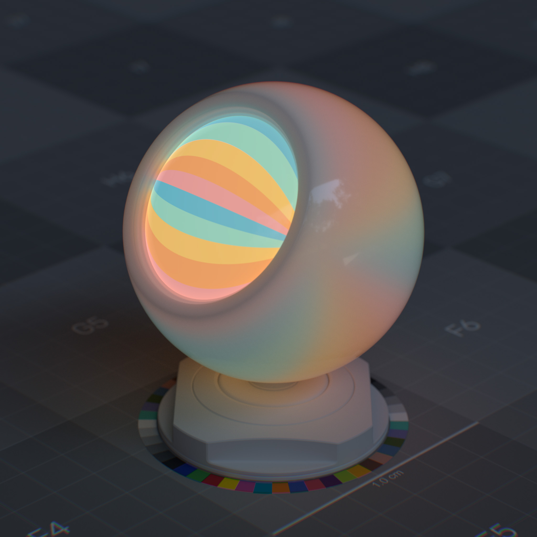
|
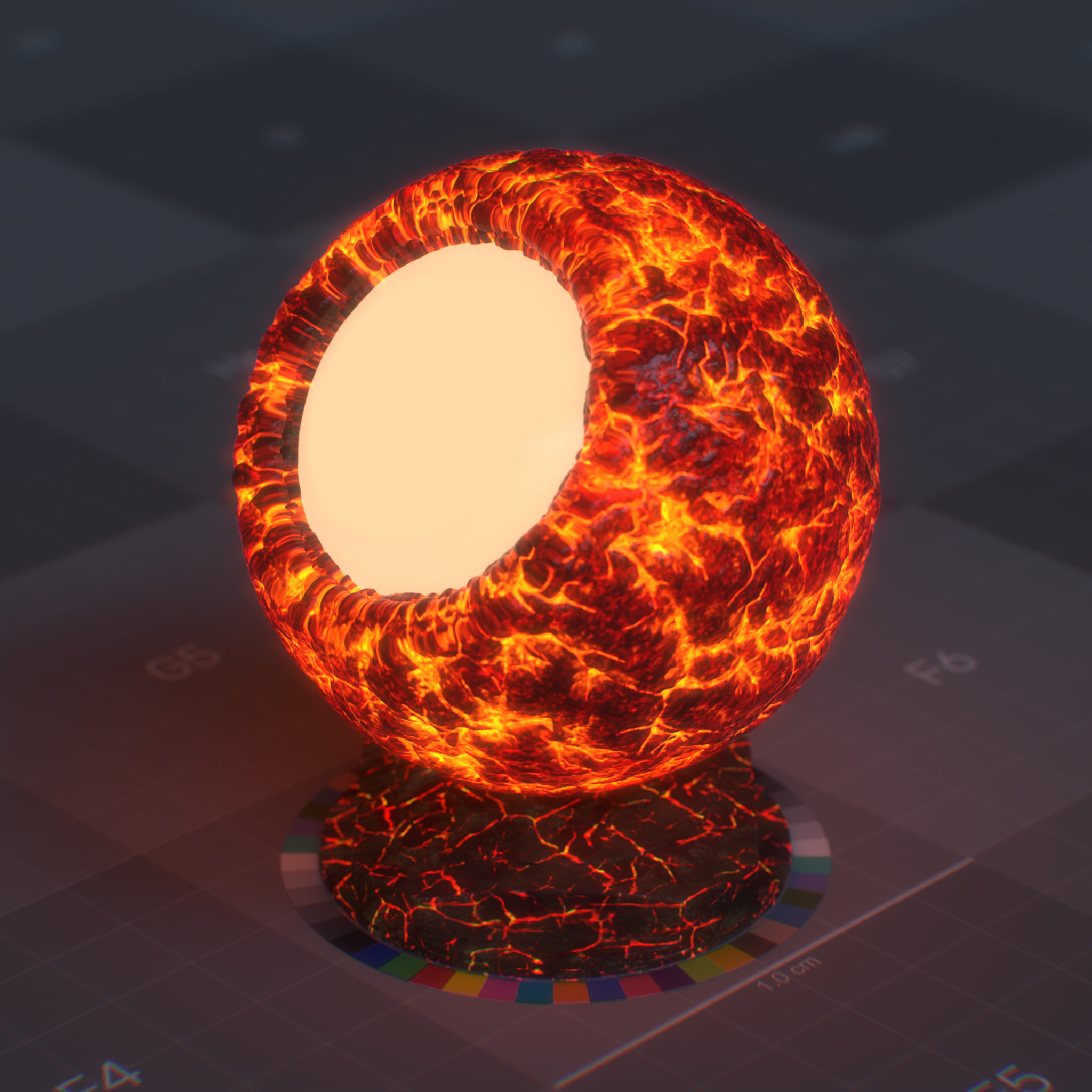
|
Use Temperature
Enable the use of color temperature value instead of color.
Note
This parameter will override the default emission color, including any textures assigned to the emission color parameter.
Temperature (Kelvin)
This parameter specifies emission color using a color temperature in the Kelvin unit. Lower values are warmer, i.e., redder, while higher values are cooler, i.e., bluer. The default value of 6500K is close to D65 illuminant, the white point in sRGB and Rec. 709 color spaces.
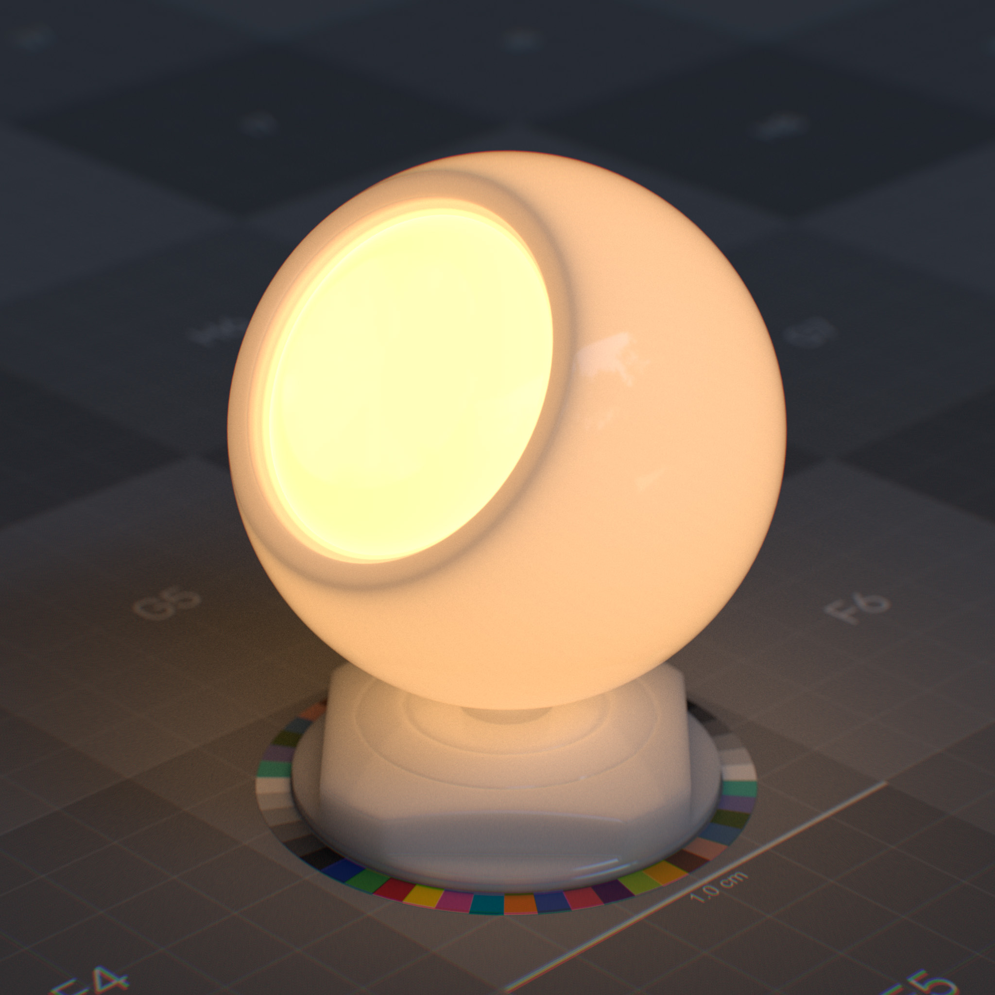
|
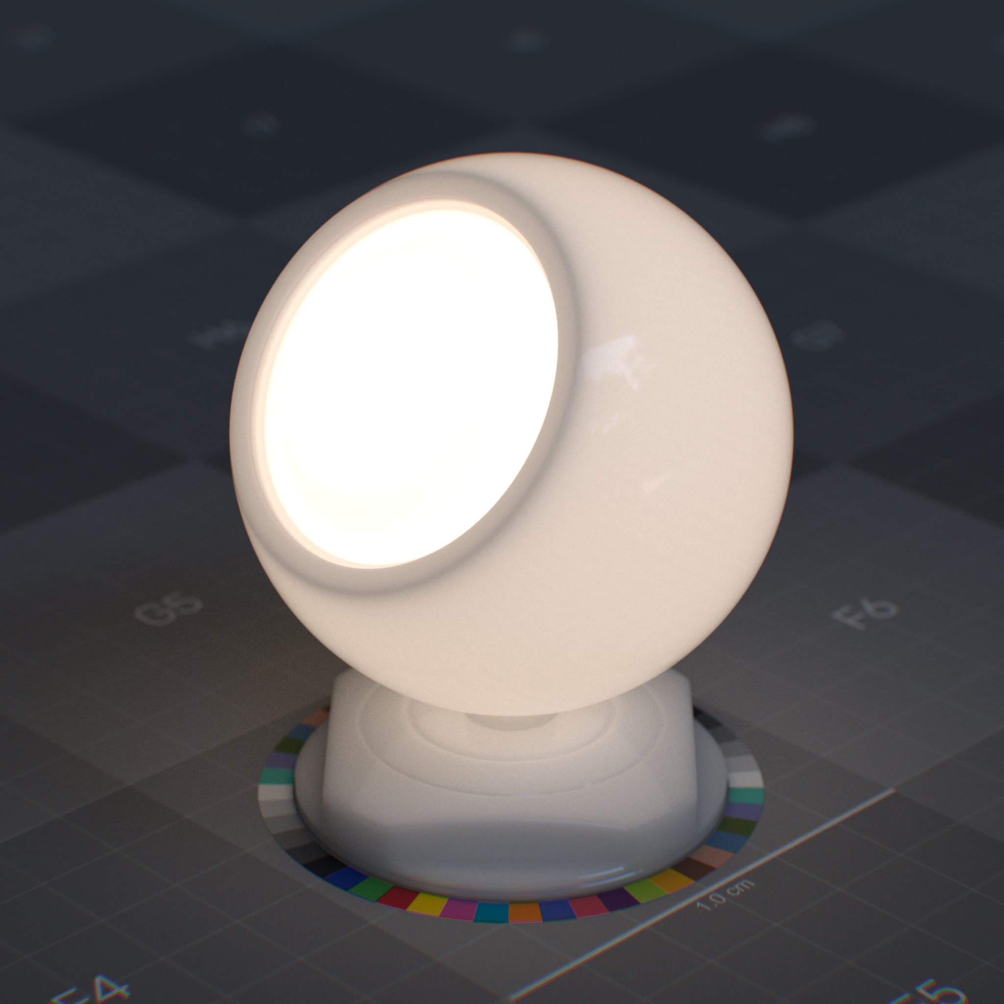
|
|
Geometry
The geometry section defines how special surface effects are calculated relative to the underlying 3D geometry. These parameters control backface visibility, opacity thresholds, thin-film effects, and depth-based adjustments like opacity attenuation.
Parameters
Display Name |
Name |
Type |
Default |
|---|---|---|---|
Thin Walled |
thin_walled |
bool |
false |
Enable Opacity |
enable_opacity |
bool |
false |
Opacity |
geometry_opacity |
float |
1.0 |
Opacity Threshold |
geometry_opacity_threshold |
float |
0.0 |
Geometry normal |
geometry_normal |
float3 |
state::normal() |
geometry_displacement |
geometry_displacement |
float3 |
0.0, 0.0, 0.0 |
Thin Walled
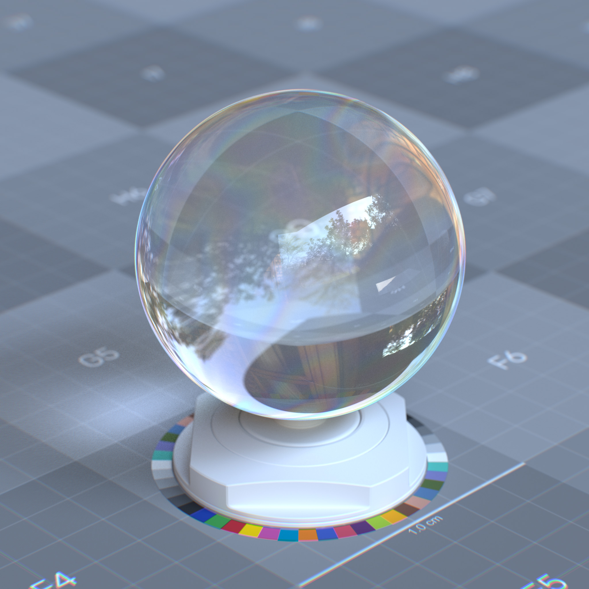
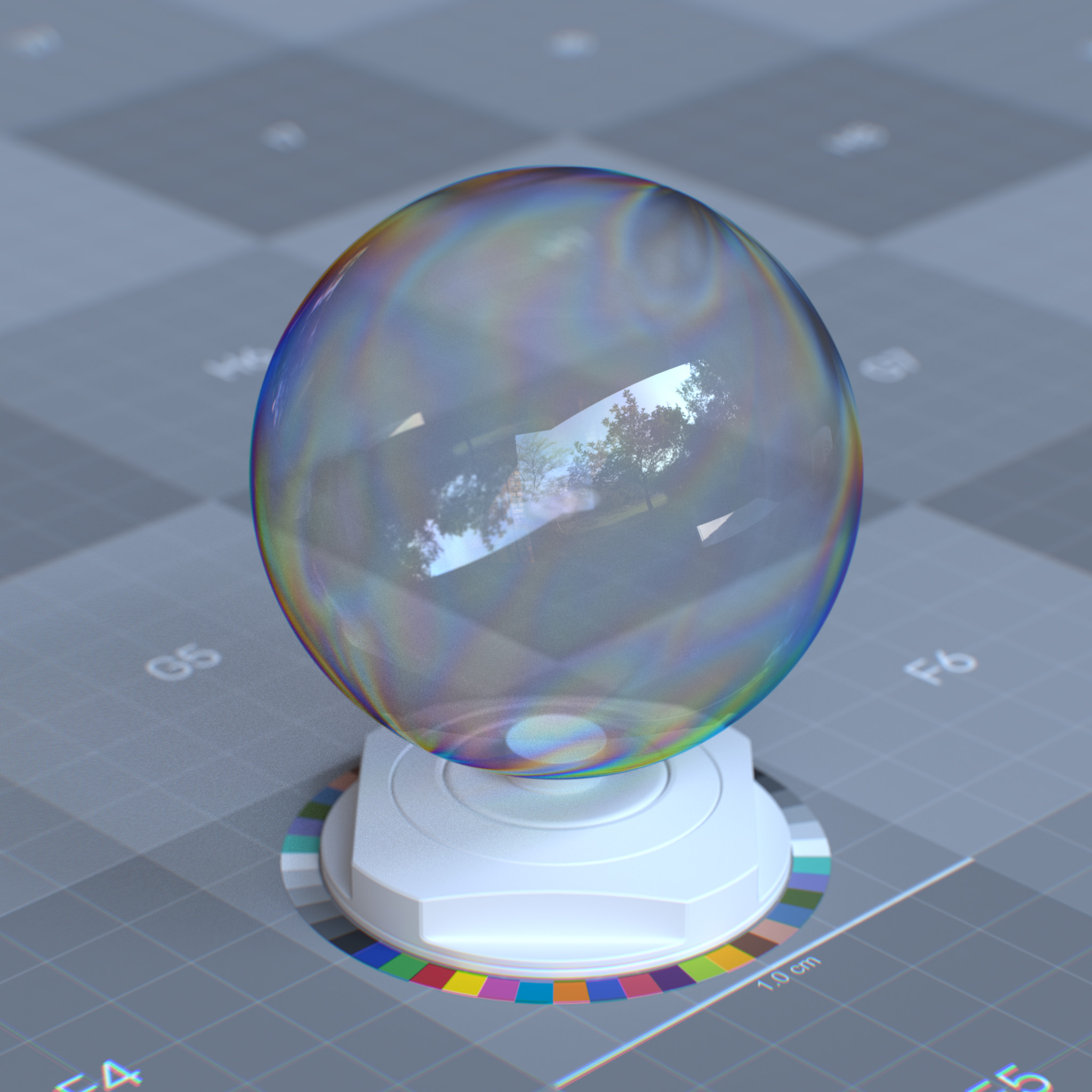
This parameter sets the surface as an infinitely thin double-sided shell with a refraction index of the surrounding medium, so refracted rays exit immediately instead of entering the medium.
Thin-walled is ideal for geometrically thin objects, like a sheet of paper, soap bubble, and leaves.
Note
“Dispersion” has no effects when Thin-Walled enabled.
|
|
Tip
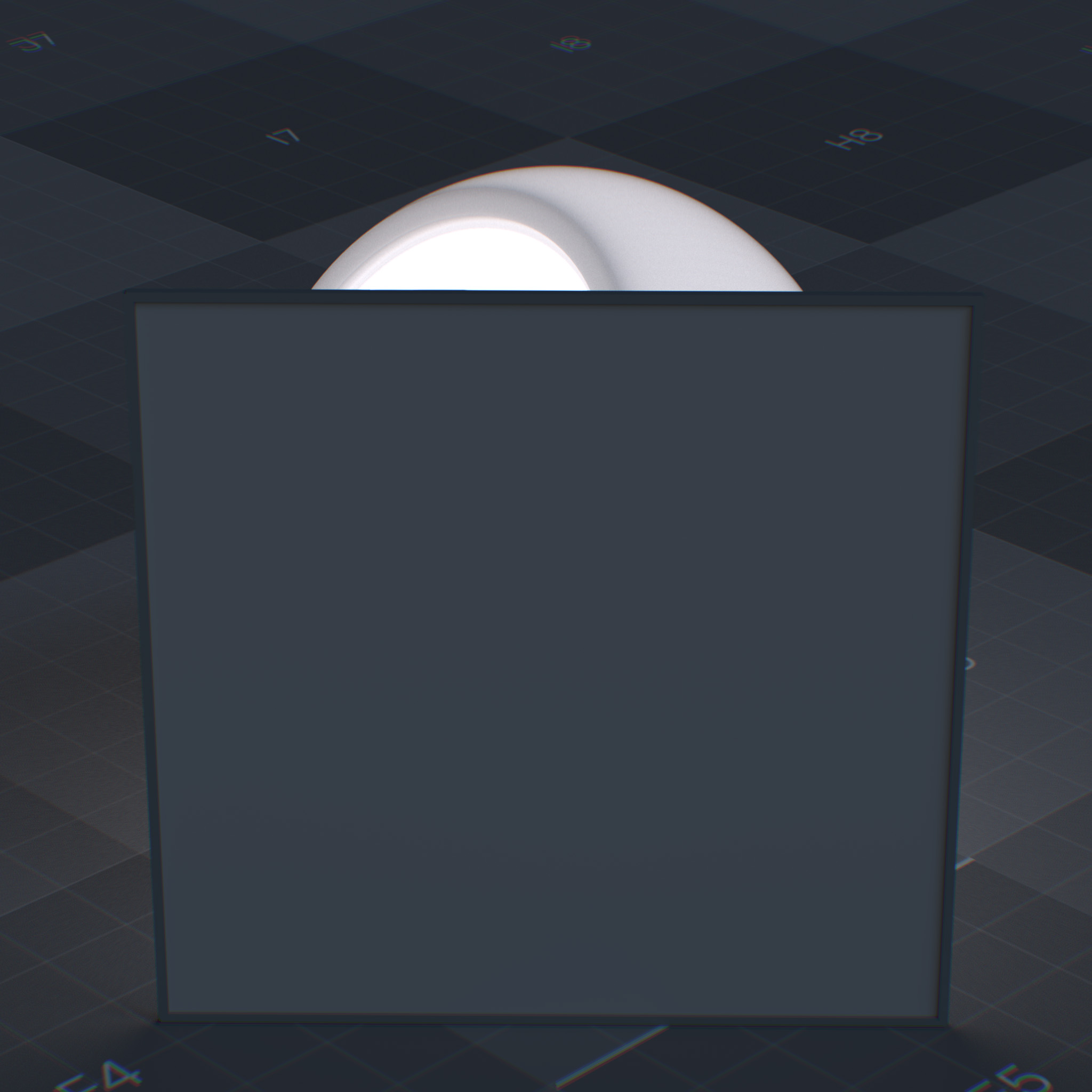
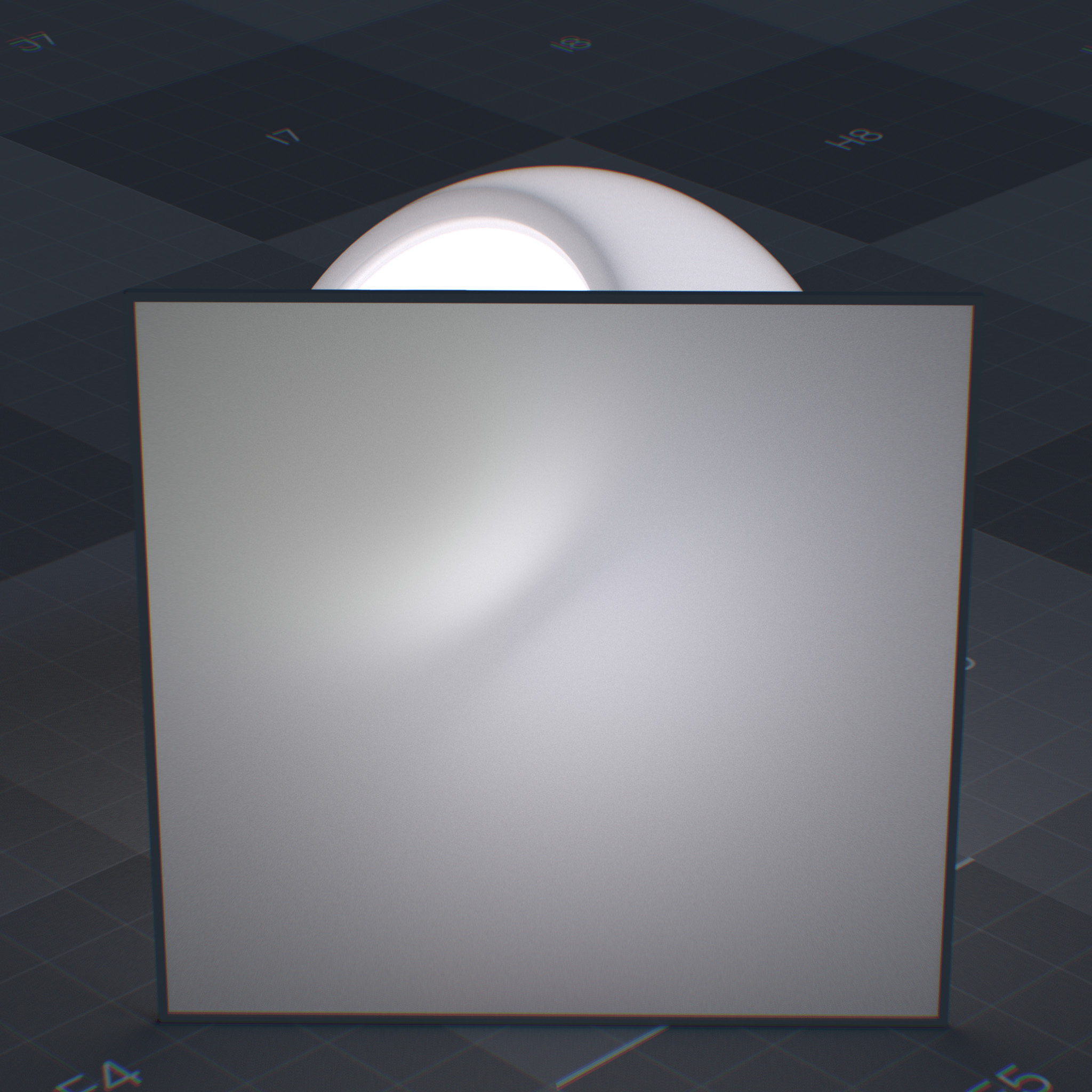
When Thin-Walled is enabled, “subsurface” is represented as the diffuse transmission of the light through an infinitely thin shell, i.e., translucence.
|
|
Enable Opacity
Enables the use of opacity
Opacity
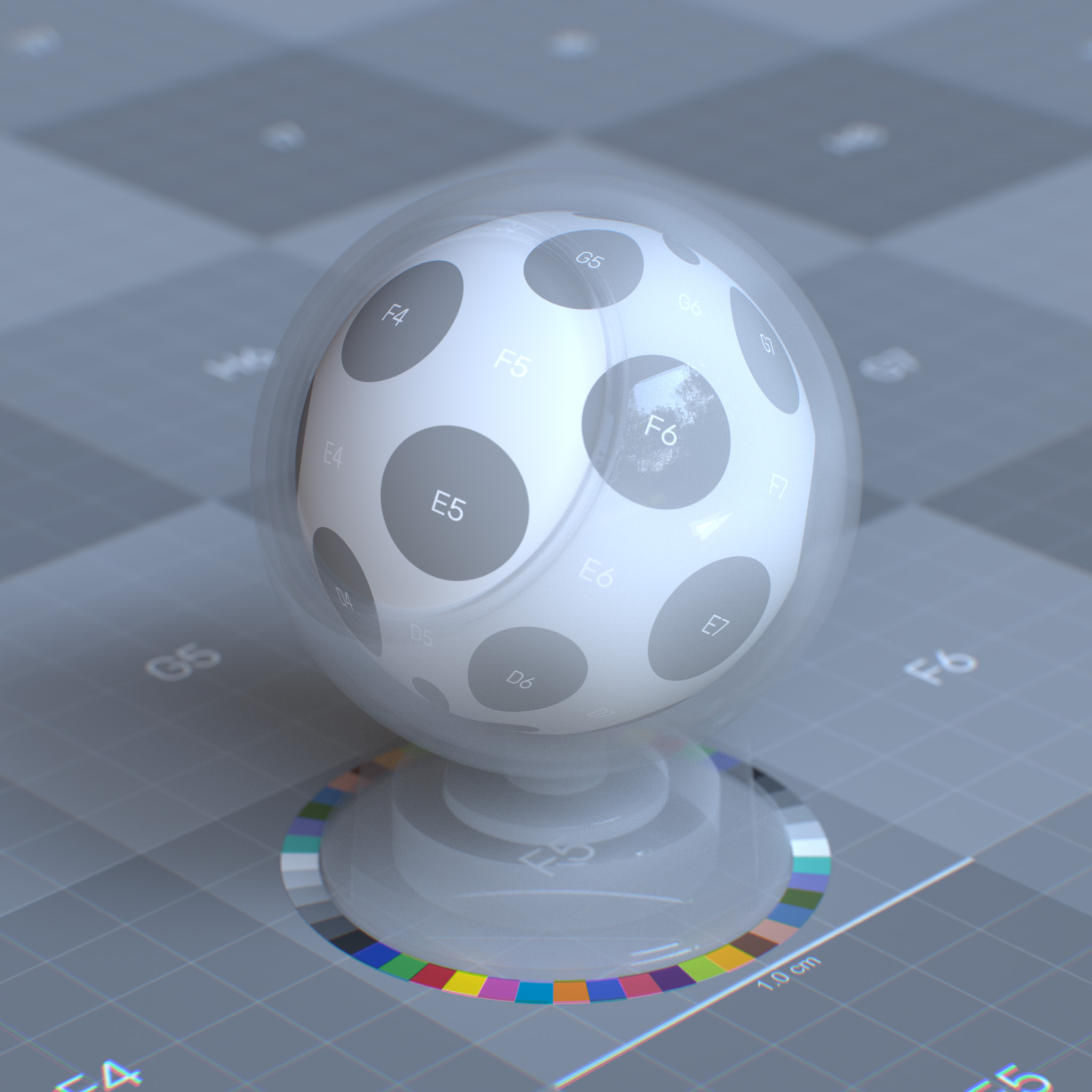
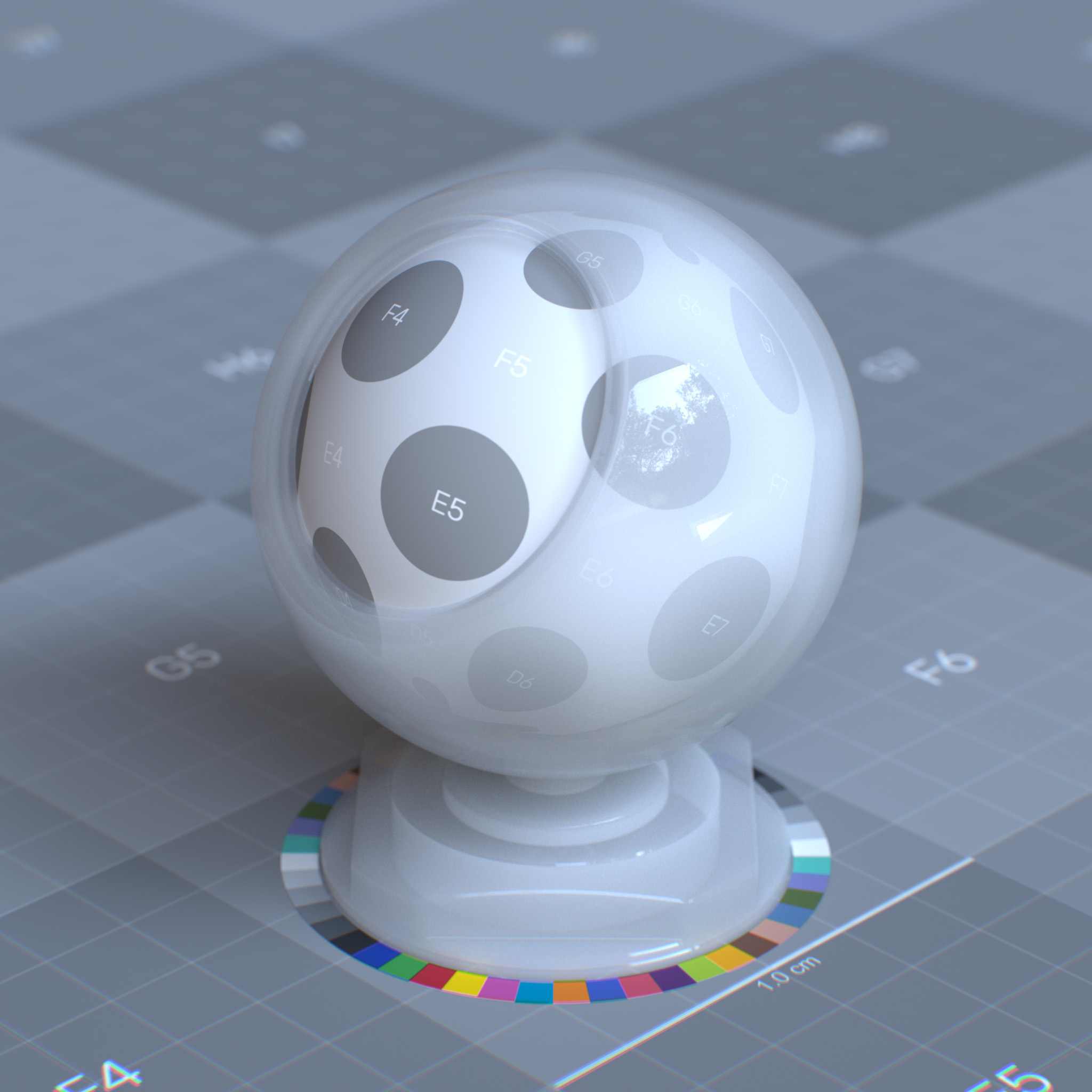
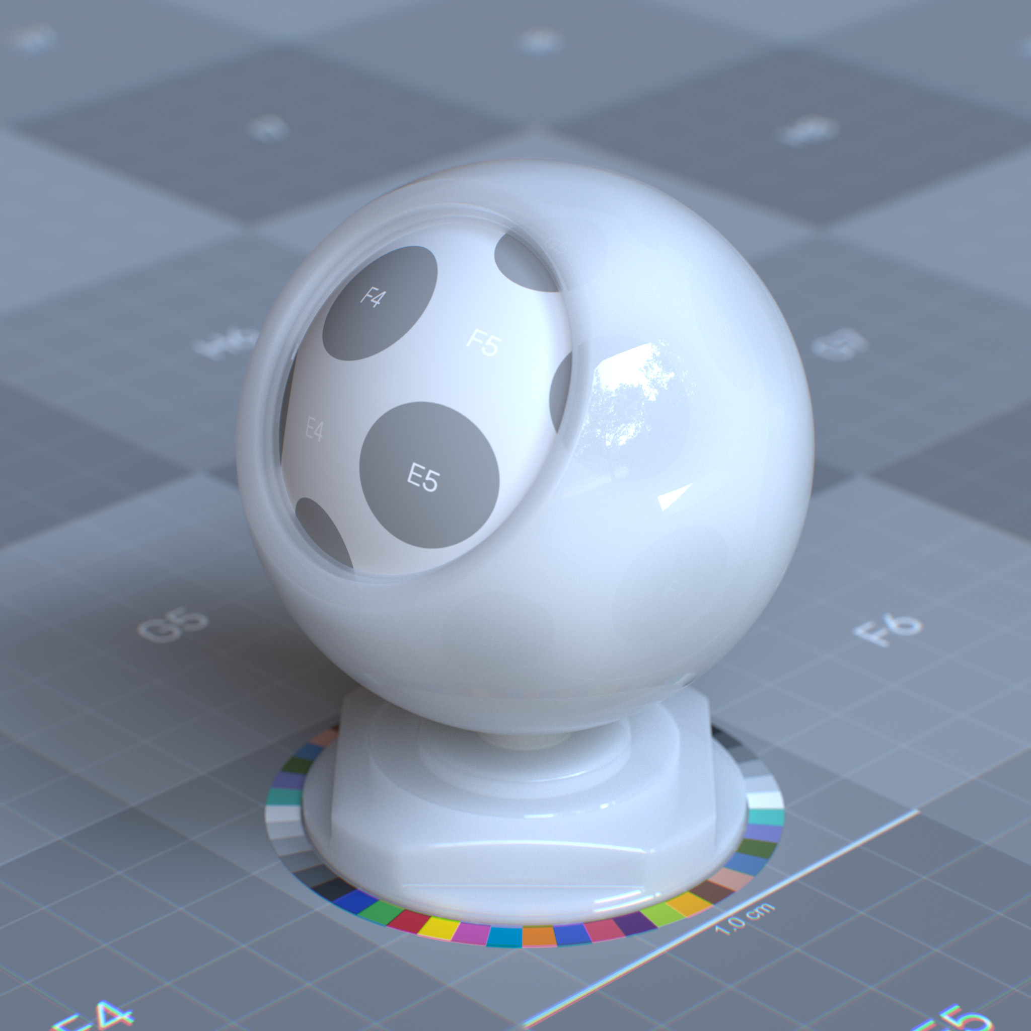
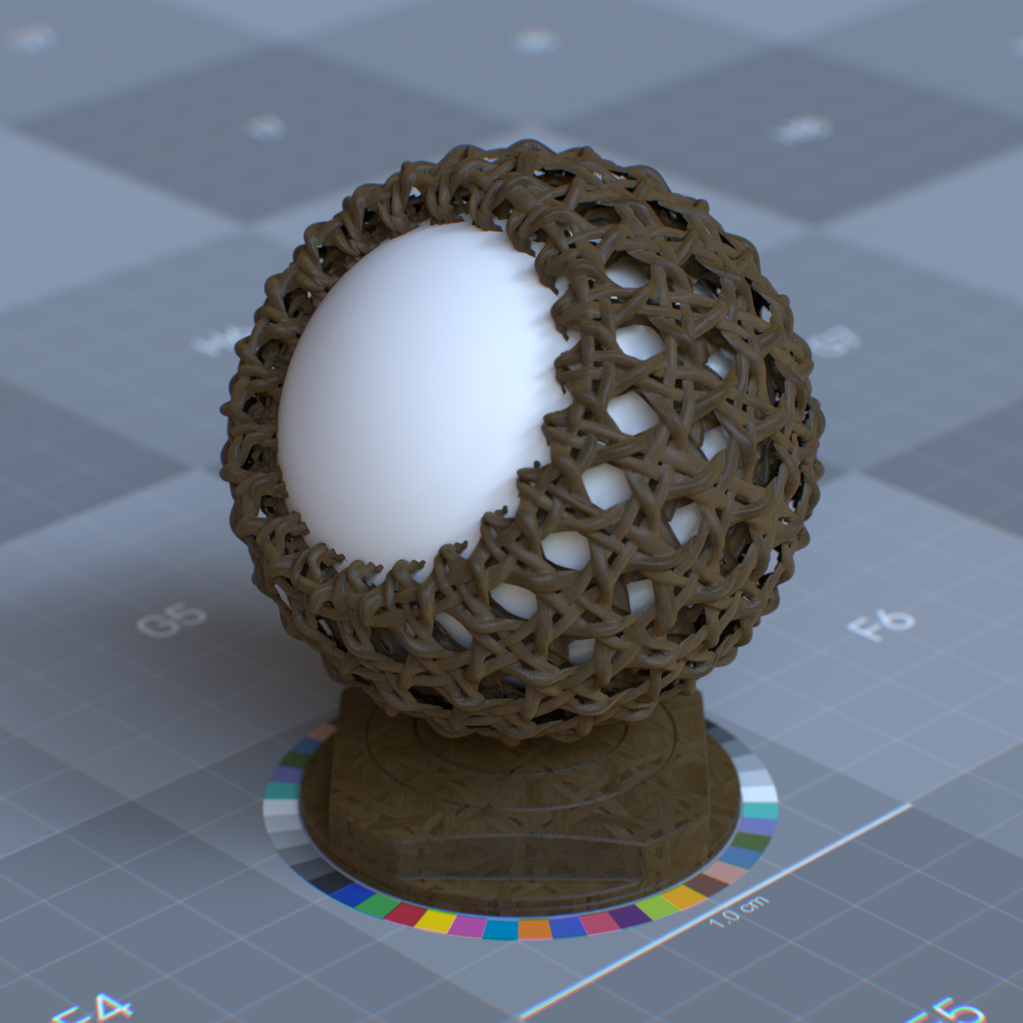
This parameter controls the travel of rays through the surface. At 0.0, the surface is invisible to the cameras, while at 1.0, it is completely opaque.
It can create render-time geometric detail on low-resolution and thin geometries.
Tip
Unlike transmission, renderers are optimized to use opacity to quickly skip over empty parts of a surface with a few operations.
|
|
|
|
Opacity Threshold
This parameter controls the opacity threshold. At a value lower or equal to the opacity map, the surface renders completely transparent. At a value greater than the opacity, the surface renders fully opaque.
Geometry Normal
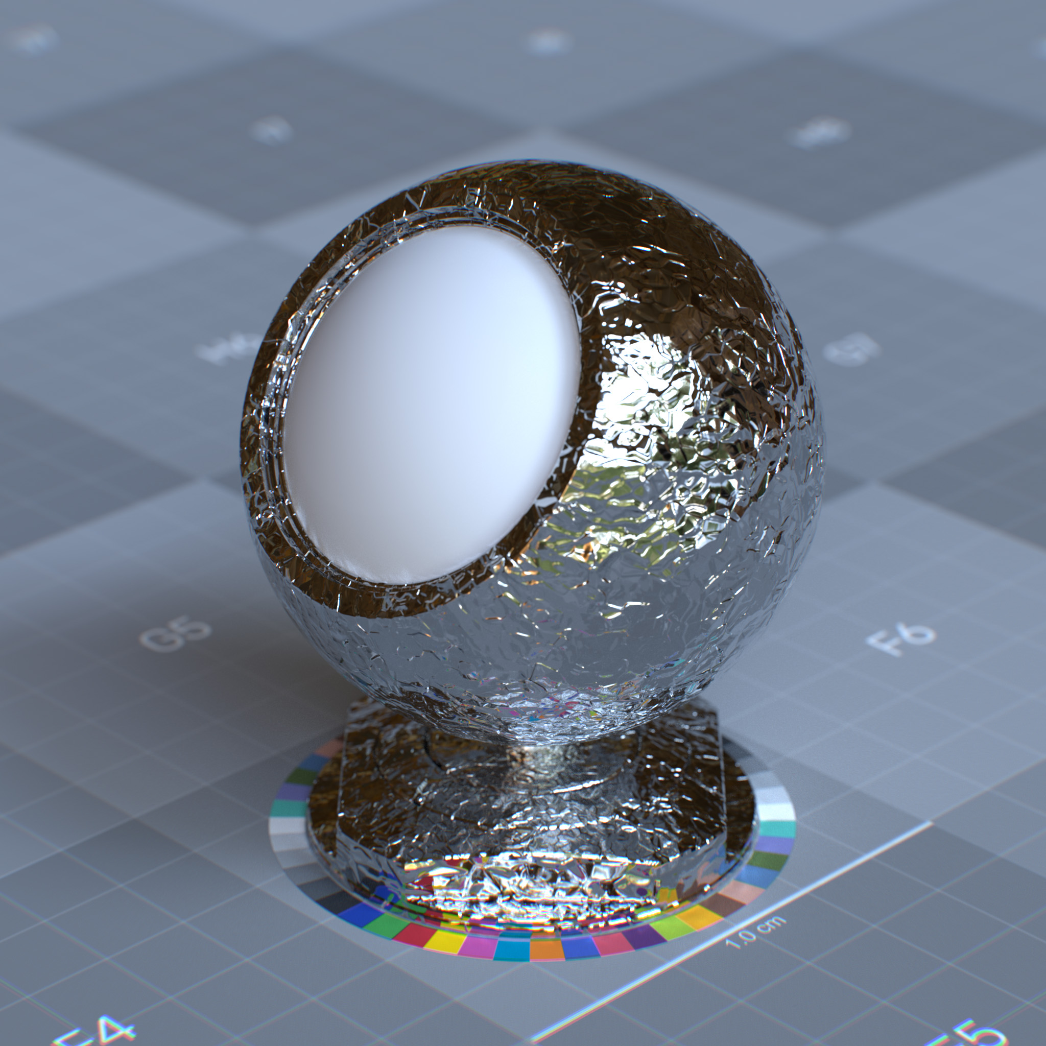
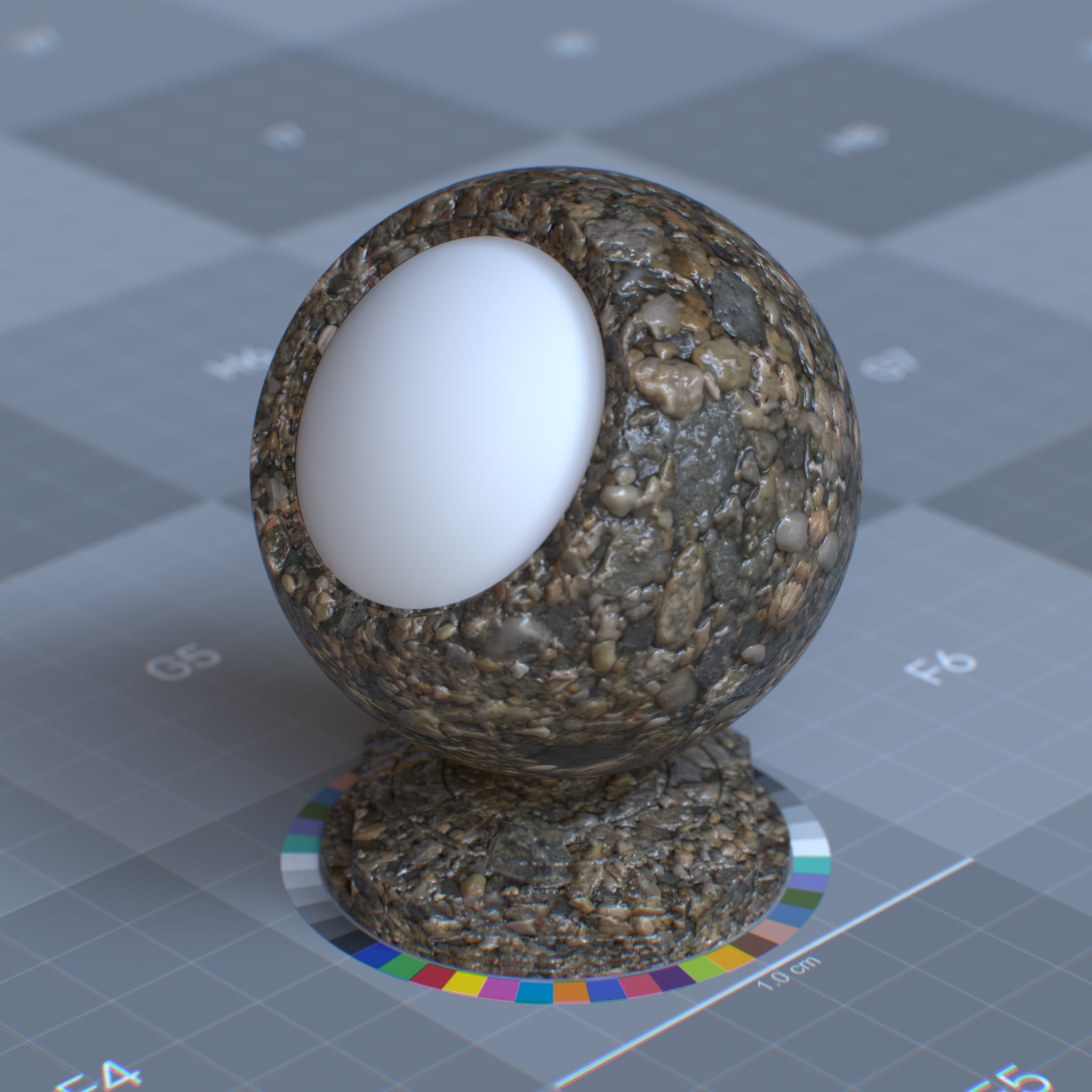
This parameter replaces the surface geometric normal with the one evaluated from a map. “Geometry Normal” has no effects on the coating layer.
|
|
Displacement
This parameter sets the direction and distance of position modification of the surface.
Important
This feature is not supported yet.
OmniSurfaceLiteBase is a subset of OmniSurfaceBase#
Parameters#
Base
The Base color of a surface before lighting calculations. Base represents only the pure color reflection of a surface, excluding lighting, shadows, or reflective properties.
Parameters
Display Name |
Name |
Type |
Default |
|---|---|---|---|
Weight |
diffuse_reflection_weight |
float |
0.8 |
Color |
diffuse_reflection_color |
color |
1.0, 1.0, 1.0 |
Diffuse Roughness |
diffuse_reflection_roughness |
float |
0.0 |
metalness |
metalness |
float |
0.0 |
This layer models the base layer, a statistical mix between diffuse reflection and diffuse transmission components.
Weight
This parameter sets the weight of diffused reflection or metallic reflectance.

|

|
Color
This parameter sets diffuse reflection color of the dielectric surface or reflectance value of metallic surface by the probability that light is reflected or transmitted for each wavelength.

|

|
Diffuse Roughness
Oren-Nayar surface roughness coefficient, simulating view-dependent diffuse reflection. At 0.0, the surface behaves similarly to a fully Lambertian reflection. Higher values are suitable for powdery surfaces like dust, sand, dried clay, concrete, etc.

|

|

|
Metalness
At 0.0, the material consists of a diffuse or transmissive base layer, with a specular reflection layer on top. When set to 1.0, the surface behaves like a metallic surface. For fully reflective metal, one can set the base weight and metalness to 1.0 and decrease specular reflection roughness to 0.0. Metalness values between 0.0 and 1.0 can create surfaces like oxidized copper when some surface areas are reflective, and some areas are not.

|

|

|

|
The metallic reflection is modeled as a GGX microfacet conductor BRDF. The absorption coefficient and complex index of refraction are computed from the base color and the specular reflection color. The base color controls the metallic surface appearance, and specular reflection weight and specular reflection color parameters only affect the edge tint.
See Thin Film section for more information.
Specular
The specular component controls direct surface reflections in materials. It simulates mirror-like behavior by defining reflection intensity, surface micro-roughness, and angle-dependent reflectivity (Fresnel effect).
Parameters
Display Name |
Name |
Type |
Default |
|---|---|---|---|
Weight |
specular_reflection_weight |
float |
1.0 |
color |
specular_reflection_color |
color |
1.0, 1.0, 1.0 |
roughness |
specular_reflection_roughness |
float |
0.2 |
IOR Preset |
specular_reflection_ior_preset |
enum |
ior_custom |
IOR |
specular_reflection_ior |
float |
1.5 |
anisotropy |
specular_reflection_anisotropy |
float |
0.0 |
Rotation (rad) |
specular_reflection_anisotropy_rotation |
float |
0.0 |
This layer models a GGX microfacet dielectric BRDF under the coating layer. Due to Fresnel, this layer is not energy conversing. Thus the energy that is not reflected is transmitted to the underlying layers.
Weight
This parameter sets the amount of the specular reflection. Lowering this value increases light transmission through the object’s volume.

|

|

|

|
When Metalness is greater than 0.0, this parameter sets the edge tint weight for the metal surface.

|

|

|
Color
This parameter sets the color of the specular reflection. While some metallic (conductor) surfaces have colored specular reflections, dielectric surfaces have only achromatic specular reflections.

|

|
Tip
Setting the specular reflection color for dielectric surfaces other than white is not physically correct.
When metalness is greater than 0.0, this parameter sets the edge tint color.

|

|
Roughness
This parameter sets the surface microfacet’s irregularities that cause light diffusion. At 0.0 simulates a perfect and smooth reflective surface, while increasing the value causes reflective highlights to diverge or appear blurred.

|

|

|

|
Roughness affects both specular reflection and specular transmission.

|

|

|

|
Tip
Roughness can create effects like torn surfaces, galvanized metal, or surfaces with fingerprints and smudges.

|

|
IOR Preset
This parameter presents a list of known IORs (index of refractions) for various materials, including glass, ice, diamond, skin. One can use custom IOR by setting this parameter to ior_custom and a value for the specular reflection’s IOR parameter.
IOR
This parameter sets IOR (index of refraction), which affects surface Fresnel reflectivity. The IOR defines the ratio between reflection on the surface front, facing the viewer, and the surface edges, facing away the viewer.
At values above 1.0, the reflection appears stronger on the surface edges and weaker on the surface front. At values less than 1.0, the Fresnel is disabled, and the specular reflection appears as a uniform highlight over the surface.
Tip
At high values, the surface will look similar to a metallic surface. If a metallic look is desired, the metalness parameter is encouraged instead since the range [0, 1] can be easily mapped with an input texture.

|

|

|
IOR affects both the specular reflection and the specular transmission.

|

|

|

|
Anisotropy
This parameter sets the specular reflection anisotropy. Reflectance changes based on the surface orientation are called anisotropic. If the reflectance is uniform in all directions and does not change based on the surface’s rotation or orientation, it is isotropic.
At values above 0.0, the surface transmits and reflects incoming light with a directional bias. Thus it appears rougher in a specific direction.

|

|

|

|
Rotation (radians)
This parameter sets the orientation of the anisotropic effect in radians. At 1.0, the anisotropic effect is rotated by 180 degrees. For brushed metallic surfaces, the anisotropic effect should stretch out in a direction perpendicular to the brushing direction.

|

|

|

|
Coat
Coat simulates an additional transparent layer on top of a base material, common in automotive paints, polished wood, and plastic coatings. This layer adds a second specular reflection with its own roughness and intensity values, independent of the underlying material properties.
Parameters
Display Name |
Name |
Type |
Default |
|---|---|---|---|
weight |
coat_weight |
float |
0.0 |
color |
coat_color |
color |
1.0, 1.0, 1.0 |
Roughness |
coat_roughness |
float |
0.1 |
IOR Preset |
coat_ior_preset |
enum |
ior_custom |
IOR |
coat_ior |
float |
1.5 |
Anisotropy |
coat_anisotropy |
float |
0.0 |
Rotation (rad) |
coat_anisotropy_rotation |
float |
0.0 |
Affect Color |
coat_affect_color |
float |
0.0 |
Affect Roughness |
coat_affect_roughness |
float |
0.0 |
Normal |
coat_normal |
float3 |
state::normal() |
This layer models GGX microfacet dielectric BRDF top coating. Due to Fresnel, this layer is not energy conserving. Thus the energy that is not reflected is transmitted to the underlying layers.
The coating simulates an infinitely thin shell dielectric layer, i.e., glass, enamel, lacquer, over the surface. It can create materials like metallic car paint, carbon fiber, oily skin, and wet asphalt.
Weight
This parameter sets the amount of surface coating. Lowering this value increases light transmission through the object’s volume.
Tip
For a realistic result, this parameter should be set to less than 1.0.

|

|

|
Color
This parameter tints all layers below the coating layer. In the real world, lights scattered by underlying layers are tinted when transmitted through the colored coating.
This parameter emulates the effect of absorption within the coating medium.
Note
The reflection color is set to white for this layer.
Roughness
This parameter sets the surface microfacet’s irregularities that cause light diffusion. At 0.0 simulates a perfect and smooth reflective surface, while increasing the value causes reflective highlights to diverge or appear blurred.
Tip
Roughness can be used to create effects like torn surfaces or surfaces with fingerprints and smudges.

|

|

|

|
IOR Preset
This parameter presents a list of known IORs (index of refractions) for various materials, including glass, ice, diamond, skin. One can use custom IOR by setting this parameter to ior_custom and a value for the specular reflection’s IOR parameter.
IOR
This parameter sets IOR (index of refraction), which affects surface Fresnel reflectivity. The IOR defines the ratio between reflection on the surface front, facing the viewer, and the surface edges, facing away the viewer.
At values above 1.0, the reflection appears stronger on the surface edges and weaker on the surface front. At values less than 1.0, the Fresnel is disabled, and the coating appears as a uniform highlight over the surface.

|

|

|
Anisotropy
his parameter sets the specular reflection anisotropy. Reflectance changes based on the surface orientation are called anisotropic. If the reflectance is uniform in all directions and does not change based on the surface’s rotation or orientation, it is isotropic.
At values above 0.0, the surface transmits and reflects incoming light with a directional bias. Thus it appears rougher in a specific direction.

|

|

|
Rotation (radian)
This parameter sets the orientation of the anisotropic effect in radians. At 1.0, the anisotropic effect is rotated by 180 degrees. For brushed surfaces, the anisotropic effect should stretch out in a direction perpendicular to the brushing direction.

|

|

|
Affect Color
This parameter controls the saturation of diffuse reflection and subsurface under the coating layer.
In the real world, refracted rays exhibit internal reflection within the coating medium, which can go back down to the underlying surface to reflect again, thus making the surface more saturated and darker. Affect Color can be used to emulate this effect. At 0.0, this parameter has no effects.

|

|

|
Affect Roughness
This parameter controls the roughness of the specular reflection, and specular transmission under the coating layer.
In the real world, refracted rays exhibit internal reflection within the coating medium, which can go back down to the underlying surface, which may scatter due to the roughness of the undercoating surface. Affect Roughness can be used to emulate this effect. At 0.0, this parameter has no effects.

Specular Reflection Weight: 1.0# Specular Reflection Roughness: 0.0 |

Coat Weight: 1.0# Coat Roughness: 0.5 |

Coat Affect Roughness: 0.0# |

Coat Affect Roughness: 1.0# |

|

|

|
Normal
This parameter sets the “normal direction” for the coating layer, which affects the Fresnel blending of the coating layer over the surface. The coat normal can create surface effects like raindrops, imperfections in car paint, or glazing on the food.
Note
The “coat normal” only affects the coating layer and has no effects on the underlying surface normal.

|

|
Emission
Emissivity defines how much light a surface emits independently of received light. This parameter creates self-illuminating effects like neon signs, screens, or bioluminescence materials. Emissivity maintains physical accuracy by contributing to scene lighting and global illumination calculations.
Parameters
Display Name |
Name |
Type |
Default |
|---|---|---|---|
Weight |
emission_weight |
float |
0.0 |
Emission Mode |
emission_mode |
enum |
emission_lx |
intensity |
emission_intensity |
float |
1.0 |
Color |
emission_color |
color |
1.0, 1.0, 1.0 |
Use Temperature |
emission_use_temperature |
bool |
false |
Temperature |
emission_temperature |
float |
6500.0 |
This layer adds directionally uniform EDF under the coating layer, which describes the light-emitting properties of the surface.
It can create materials like an incandescent light-bulb, glowing lava, and LED panel.
Note
In the RTX – Interactive (Path Tracing) mode, to reduce the noise in the indirectly lit area using emissive materials, one may need to increase the Total Samples per Pixel.
Please see RTX Interactive (Path Tracing) mode render settings for more information.

|

|

|

|
Weight
This parameter sets the amount of light emission from the surface.

|

|

|

|
Emission Mode
This parameter specifies the physical units to use for the emission intensity.
1. “Nit” is the unit of luminance and describes the surface power of a visible light source. The overall illumination of the scene changes depends on the size of the light source.
One nit is equal to one candela per square meter. 1 nit = 1 cd/m^2
The candela per square meter is the base unit of luminance. Candela is the base unit for luminous intensity.
A light source that emits one candela of luminous intensity onto an area of one square meter has a luminance of one candela per square meter or one nit. As an example, a calibrated monitor has a brightness of 120 cd/m^2 or 120 nits.
2. “Lux” is the unit of illuminance and describes the total amount of visible light that a light source emits. The overall illumination of the scene does not change depending on the size of the light source.
One lux is equal to one lumen per square meter. 1 lux = 1 lm/m^2
A light source that emits one candela of luminous intensity from an area of one steradian has a luminous flux of one lumen.
A light source that emits one lumen of luminous flux onto an area of one square meter has an illuminance of one lux. As an example, very bright sunlight has a brightness of 120,000 lux.
Intensity
This parameter sets the emission intensity. The emission mode parameter sets the physical unit for this parameter.
A few examples of illuminance under various lighting conditions:
Lighting Condition |
Illuminance (lx) |
|---|---|
Sunlight |
100,000 - 120,000 |
Daylight |
10,000 - 25,000 |
Overcast |
1000 |
Twilight |
10 |
Full moon |
0.05 – 0.3 |
Ceiling lamp |
400 - 800 |
Table lamp |
200 - 300 |
Candle light |
12.57 |
Color
This parameter sets the emission color.

|

|
Use Temperature
Enable the use of color temperature value instead of color.
Note
This parameter will override the default emission color, including any textures assigned to the emission color parameter.
Temperature (Kelvin)
This parameter specifies emission color using a color temperature in the Kelvin unit. Lower values are warmer, i.e., redder, while higher values are cooler, i.e., bluer. The default value of 6500K is close to D65 illuminant, the white point in sRGB and Rec. 709 color spaces.

|

|

|
Geometry
The geometry section defines how special surface effects are calculated relative to the underlying 3D geometry. These parameters control backface visibility, opacity thresholds, thin-film effects, and depth-based adjustments like opacity attenuation.
Parameters
Display Name |
Name |
Type |
Default |
|---|---|---|---|
Thin Walled |
thin_walled |
bool |
false |
Enable Opacity |
enable_opacity |
bool |
false |
Opacity |
geometry_opacity |
float |
1.0 |
Opacity Threshold |
geometry_opacity_threshold |
float |
0.0 |
Geometry normal |
geometry_normal |
float3 |
state::normal() |
geometry_displacement |
geometry_displacement |
float3 |
0.0, 0.0, 0.0 |
Thin Walled
This parameter sets the surface as an infinitely thin double-sided shell with a refraction index of the surrounding medium, so refracted rays exit immediately instead of entering the medium.
Thin-walled is ideal for geometrically thin objects, like a sheet of paper, soap bubble, and leaves.
Note
“Dispersion” has no effects when Thin-Walled enabled.

|

|
Tip
When Thin-Walled is enabled, “subsurface” is represented as the diffuse transmission of the light through an infinitely thin shell, i.e., translucence.

|

|
Enable Opacity
Enables the use of opacity
Opacity
This parameter controls the travel of rays through the surface. At 0.0, the surface is invisible to the cameras, while at 1.0, it is completely opaque.
It can create render-time geometric detail on low-resolution and thin geometries.
Tip
Unlike transmission, renderers are optimized to use opacity to quickly skip over empty parts of a surface with a few operations.

|

|

|

|
Opacity Threshold
This parameter controls the opacity threshold. At a value lower or equal to the opacity map, the surface renders completely transparent. At a value greater than the opacity, the surface renders fully opaque.
Geometry Normal
This parameter replaces the surface geometric normal with the one evaluated from a map. “Geometry Normal” has no effects on the coating layer.

|

|
Displacement
This parameter sets the direction and distance of position modification of the surface.
Important
This feature is not supported yet.
Note
- The non base materials provide additional parameters for direct texture mapping control. The following shows
a generic example.
Image: Path to a valid color or grayscale image in a supported format.
Weight: Scalar value defining the Image contribution.
Weight Image: A texture map defining the Image contribution, multiplied by the Weight parameter.
Alpha Mode: If the Mappable parameter is of type float, this dropdown will determine how to utilize the Image.
Valid Opacity Map Mono Source Values
- Specifies opacity channel or evaluation of the map for opacity.
mono_alpha : Uses the alpha channel of the image as the source for evaluation.
mono_average : Uses the average of the RGB channels as the source for evaluation.
mono_luminance : Uses the luminance of the image as the source for evaluation.
mono_maximum : Uses the max value of the RGB channels as the source for evaluation.
