Lights#
Overview#
Lighting in Omniverse Kit-based apps offers a wide variety of lighting options and capabilities.
Update to the UsdLux Lighting Specification#
In OpenUSD 25.05, the UsdLux lighting documentation was updated to resolve ambiguities in how the various attributes that affect lights’ emission behave. The changes mean that applications that conform to the new specification will generate images of the same brightness given the same USD layer, which was not the case previously.
Controlling the UsdLux Behavior#
In Omniverse, the behavior of any individual light is controlled by the attribute int omni:rtx:usdluxVersion, which defaults to 2411 (the old behavior) when not applied. The new behavior can be selected by setting this attribute to 2505 or greater. Note that this attribute will be deprecated in a future version, and all lights will be assumed to have 25.05 behavior. See Upgrading Existing Lights for how to upgrade existing scenes to the new specification.
As of Kit 109.0, all lights are created with int omni:rtx:usdluxVersion = 2505. This behavior can be changed by passing --/rtx/lighting/defaultUsdLuxVersion=2411 on the Kit command line.
Upgrading Existing Lights#
Existing scenes can be upgraded to the new specification while preserving their look by running:
import omni.kit.commands
omni.kit.commands.execute("UpgradeUsdLuxLights", use_session_layer=<bool, default False>)
The optional use_session_layer argument can be used to direct the command to perform the upgrade in the session layer, where changes do not persist when saving the stage file. By default, the command will perform the upgrade in the root layer, where changes persist when saving the stage file.
This command will run on any lights that do not already have int omni:rtx:usdluxVersion = 2505 and will add that attribute and remap their attributes in order to maintain their look under the new specification.
After running the command, and before saving the stage file, inspect the results of the upgrade and verify the lights look as expected. Consider running the command first with the use_session_layer argument set to True to verify the results in the session layer; if the results are as expected, reopen the stage file and run the command again without the use_session_layer argument to perform the upgrade in the root layer. Before saving the stage file, inspect the results again and verify that the lights look as expected.
You should also make a backup of the stage files and assets before running the command, or maintain them under version control, should the need arise to revert the changes if they were saved accidentally.
Significant Changes in UsdLux 25.05#
Distant Lights#
Previously, RTX did not respect the value of
bool inputs:normalize, assuming that the light was always normalized. RTX now respects the value of this attribute.
Dome Lights#
Previously, RTX oriented the dome light such that a default camera would be looking at the “bottom” of the image. Now the default orientation is such that a default camera will be looking at the horizon. The additional transform that Kit previously applied to dome lights to correct for this has been removed.
Area Lights#
The mapping for
inputs:shaping:cone:softnesshas changed to match the new specification.RTX now respects the
inputs:shaping:ies:angleScaleattribute, which allows the distribution of an IES light to be “squashed” or “expanded” for creative control.
Light Sources#
Light sources in Kit-based apps are made to realistically emulate real-world lights.
Light Types |
Real World Equivalent
|
|---|---|
Distant Light |
Direct Sun/Moon light
|
Sphere Light |
Light Bulb
|
Rect Light |
Rectangular Panel Light
|
Disk Light |
Circular Panel Lights and Spotlights
|
Cylinder Light |
Neon/Fluorescent Light Tubes
|
Dome Light |
HDRI Skysphere (Background) lighting
|
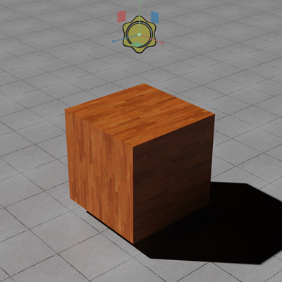
Distant Light#
Distant lights are parallel rays of light useful for showering an entire scene in a directional light. Meant to emulate lights infinitely far away, shadows cast with type of light will be hard edged and rather harsh compared to other lights. Ideal for Sun/Moon light, distant lights are generally a critical element to any outdoor scene.
Sphere Light#
Sphere lights emit light in all directions from a central ball (not a point). The softness of the shadows (and overall intensity) are dictated by the radius of the central ball. Sphere lights are effective replacements for light bulbs.
Light Specific Properties |
Usage |
|---|---|
Radius |
Source Sphere Radius |
Treat as Point |
Makes the sphere size infinitely small |
Rectangular (Rect) Light#
Rectangular lights are capable of emulating light generated from a panel. The rectangle can be adjusted in width and length to accommodate any ratio from thin rectangle to square shape. This affect overall light power and shadow softness.
Light Specific Properties |
Usage |
|---|---|
Height |
Depth of the light source (x value) |
Length |
Length of the source (y value) |
Projector light type |
Enables focusing a textured light like a projector. Scale the light as desired to adjust the focus area. |
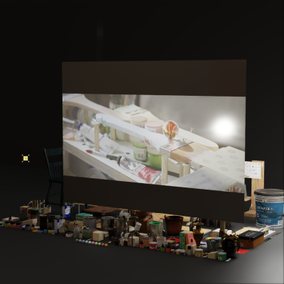
Projector Light#
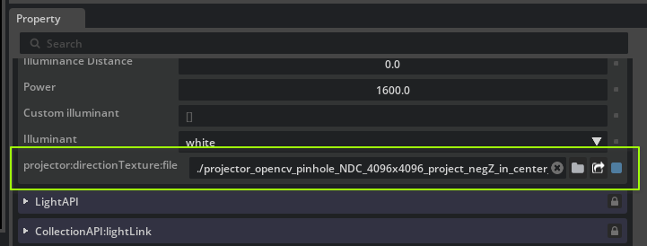
Enabling Projector light type on a RectLight causes the assigned Texture File to be projected onto the scene as from a slide projector. The shape of the projection may be controlled using the asset projection:directionTexture:file, which works the same way as OmniLensDistortionLutAPI. That is, the direction texture specifies the exitant direction of the light at each point over the light’s surface.
In Kit applications, the asset projection:directionTexture:file attribute can be found in the Extra Properties section:
Projector Direction Texture Generation#
The exit direction of the projector at any point on the light’s surface is read from a pre-generated LUT stored in a 32-bit float OpenEXR texture file. Each pixel’s red and green channels encode the NDC-space (Normalized Device Coordinate), octahedral-encoded direction. The example Python script below converts an OpenCV pinhole calibration to a direction texture that can be used directly.
Example Projector Direction Texture Generation Python Script
This script shows how to generate a correctly encoded LUT stored in an OpenEXR from the OpenCV pinhole model.
  1# Copyright (c) 2024, NVIDIA CORPORATION. All rights reserved.
  2#
  3# NVIDIA CORPORATION and its licensors retain all intellectual property
  4# and proprietary rights in and to this software, related documentation
  5# and any modifications thereto. Any use, reproduction, disclosure or
  6# distribution of this software and related documentation without an express
  7# license agreement from NVIDIA CORPORATION is strictly prohibited.
  8
  9
 10# This script can generate textures compatible with the "GeneralizedProjectionTexture" lens projection.
 11# It generates a forward/inverse texture pair that drives the projection.
 12# This script can generate these textures by mimicking the existing omni fisheye projections
 13# and baking them as textures.
 14# This python script will require pipinstalls for the following python libraries:
 15
 16# /// script
 17# dependencies = [
 18#   "OpenEXR",
 19#   "numpy",
 20# ]
 21# ///
 22
 23import OpenEXR
 24import Imath
 25import numpy as np
 26from numpy.polynomial.polynomial import polyval
 27
 28# Compression for the .exr output file
 29# Should be one of:
 30# NO_COMPRESSION | RLE_COMPRESSION | ZIPS_COMPRESSION | ZIP_COMPRESSION | PIZ_COMPRESSION
 31#g_compression = Imath.Compression.NO_COMPRESSION
 32g_compression = Imath.Compression.ZIP_COMPRESSION
 33
 34
 35# util functions
 36def save_img(img_path: str, img_data):
 37    """ Saving a numpy array to .exr file """
 38
 39    if img_data.ndim != 3:
 40        raise "The input image must be a 2-Dimensional image"
 41
 42    height = img_data.shape[0]
 43    width = img_data.shape[1]
 44    channel_count = img_data.shape[2]
 45
 46    channel_names = ['R', 'G', 'B', 'A']
 47
 48    channel_map = {}
 49    channel_data_types = {}
 50
 51    for i in range(channel_count):
 52        channel_map[channel_names[i]] = img_data[:, :, i].tobytes()
 53        channel_data_types[channel_names[i]] = Imath.Channel(Imath.PixelType(Imath.PixelType.FLOAT))
 54
 55    header = OpenEXR.Header(width, height)
 56    header['Compression'] = g_compression
 57    header['channels'] = channel_data_types
 58    exrfile = OpenEXR.OutputFile(img_path, header)
 59    exrfile.writePixels(channel_map)
 60    exrfile.close()
 61
 62def oct_to_unit_vector(x, y):
 63    """Decode an array of X and Y UV coordinates in range (-1, 1) into directions."""
 64    # Handle both 1D arrays (create meshgrid) and 2D arrays (use directly)
 65    if x.ndim == 1 and y.ndim == 1:
 66        dirX, dirY = np.meshgrid(x, y)
 67    else:
 68        dirX, dirY = x, y
 69
 70    dirZ = 1 - np.abs(dirX) - np.abs(dirY)
 71
 72    sx = 2 * np.heaviside(dirX, 1) - 1
 73    sy = 2 * np.heaviside(dirY, 1) - 1
 74
 75    tmpX = dirX
 76    dirX = np.where(dirZ <= 0, (1 - abs(dirY)) * sx, dirX)
 77    dirY = np.where(dirZ <= 0, (1 - abs(tmpX)) * sy, dirY)
 78
 79    n = 1 / np.sqrt(dirX**2 + dirY**2 + dirZ**2)
 80    dirX *= n
 81    dirY *= n
 82    dirZ *= n
 83    return dirX, dirY, dirZ
 84
 85def unit_vector_to_oct(dirX, dirY, dirZ):
 86    """Encode an array of view directions (unit vectors) into octahedral encoding."""
 87    n = 1 / (np.abs(dirX) + np.abs(dirY) + np.abs(dirZ))
 88    octX = dirX * n
 89    octY = dirY * n
 90
 91    sx = 2*np.heaviside(octX, 1) - 1
 92    sy = 2*np.heaviside(octY, 1) - 1
 93
 94    tmpX = octX
 95    octX = np.where(dirZ <= 0, (1 - abs(octY)) * sx, octX)
 96    octY = np.where(dirZ <= 0, (1 - abs(tmpX)) * sy, octY)
 97    return octX, octY
 98
 99def get_octahedral_directions(width, height):
100    """Generate view directions for each texel using octahedral mapping.
101
102    Args:
103        width, height: Texture dimensions
104
105    Returns:
106        dirX, dirY, dirZ: Direction arrays with proper texel center sampling
107    """
108    # Generate coordinates for texel centers
109    # Create coordinate arrays for texel centers
110    x_indices = np.arange(width) + 0.5
111    y_indices = np.arange(height) + 0.5
112
113    # Convert to UV coordinates in [0, 1] range
114    u = x_indices / width
115    v = y_indices / height
116
117    # Convert UV to octahedral coordinates in [-1, 1] range
118    oct_x = u * 2.0 - 1.0
119    oct_y = v * 2.0 - 1.0
120
121    # Create meshgrids for 2D arrays
122    X, Y = np.meshgrid(oct_x, oct_y)
123
124    # octahedral to unit vector
125    dirX, dirY, dirZ = oct_to_unit_vector(X, Y)
126
127    return dirX, dirY, dirZ
128
129
130# KB distortion model
131def poly_KB(theta, coeffs_KB):
132    theta2 = theta**2
133    dist = 1 + theta2 * (coeffs_KB[1] + theta2 * (coeffs_KB[2] + theta2 * (coeffs_KB[3] + theta2 * coeffs_KB[4])))
134    return theta * dist
135
136# Unproject from sensor plane normalized coordinates to ray cosine directions
137def create_backward_KB_distortion(dest_texture_width, dest_texture_height, width, height, fx, fy, cx, cy, coeffs_KB):
138    from scipy.optimize import root_scalar
139
140    # Create a 2d array of values from [0-cx, 1-cx]x[0-cy, 1-cy], and normalize to opencv angle space.
141    # Note scale from -0.5 to 0.5, hence sparing width/2.
142    screen_x = (np.linspace(0, 1, dest_texture_width) - cx) * width / fx
143    screen_y = (np.linspace(0, 1, dest_texture_height) - cy) * height / fy
144
145    # y is negated here to match the inverse function's behavior.
146    # Otherwise, rendering artifacts occur because the functions don't match.
147    screen_y = [-y for y in screen_y]
148
149    X, Y = np.meshgrid(screen_x, screen_y)
150
151    # Compute the radial distance on the screen from its center point
152    R = np.sqrt(X**2 + Y**2)
153
154    def find_theta_for_R(R, coeffs_KB):
155        if R > 0:
156            # Define a lambda function for the current R
157            func = lambda theta: poly_KB(theta,coeffs_KB) - R
158            # Use root_scalar to find the root
159            theta_solution = root_scalar(func,
160                                         bracket=[0, np.pi/1],
161                                         method='brentq',
162                                         xtol=1e-12, # Controls absolute tolerance
163                                         rtol=1e-12, # Control relative tolerance
164                                         maxiter=1000) # Set max iteration
165            return theta_solution.root
166        else:
167            return 0  # Principal point maps to z-axis
168
169    # Vectorize the function
170    vectorized_find_theta = np.vectorize(find_theta_for_R, excluded=coeffs_KB)
171    theta = vectorized_find_theta(R, coeffs_KB)
172
173    # compute direction consines.
174    X = X / R
175    Y = Y / R
176    sin_theta = np.sin(theta)
177    dirX = X * sin_theta
178    dirY = Y * sin_theta
179    dirZ = -np.cos(theta)
180
181    # set the out of bound angles so that we can clip it in shaders
182    dirX = np.where(abs(theta) >= np.pi, 0, dirX)
183    dirY = np.where(abs(theta) >= np.pi, 0, dirY)
184    dirZ = np.where(abs(theta) >= np.pi, 1, dirZ)
185
186    return dirX, dirY, dirZ
187
188# Project directions to NDC using KB distortion model
189def create_forward_KB_distortion_given_directions(dirX, dirY, dirZ, width, height, fx, fy, cx, cy, coeffs_KB):
190
191    # Flip the z direction to encode the directions along -Z in the center of the texture:
192    # Since camera faces negative Z in view space, most of the contribution to the image comes from the negative Z direction
193    # We want to encode the negative Z directions in the center of the texture to have no interpolation issues on the edge.
194    dirZ = -dirZ
195
196    # Compute theta between ray and optical axis
197    sin_theta = np.sqrt(dirX**2 + dirY**2)
198    theta = np.arctan2(sin_theta, -dirZ)
199
200    # Apply forward distortion model
201    y = poly_KB(theta, coeffs_KB)
202
203    # Normalize to render scale
204    Rx = y / width * fx
205    Ry = y / height * fy
206    dirX = np.where(sin_theta != 0, dirX * (Rx / sin_theta), dirX)
207    dirY = np.where(sin_theta != 0, dirY * (Ry / sin_theta), dirY)
208
209    return dirX + cx, dirY + cy
210
211def create_forward_KB_distortion_octahedral(dest_texture_width, dest_texture_height, width, height, fx, fy, cx, cy, coeffs):
212    """Create KB distortion projection using octahedral encoding."""
213    # Convert each texel coordinate into a view direction, using octahedral decoding
214    dirX, dirY, dirZ = get_octahedral_directions(dest_texture_width, dest_texture_height)
215
216    # Project the decoded view direction into NDC
217    # Note: Replace this call with your own projection function if needed
218    return create_forward_KB_distortion_given_directions(dirX, dirY, dirZ, width, height, fx, fy, cx, cy, coeffs)
219
220def generate_hq_fisheye_KB(dest_texture_width, dest_texture_height, width, height, fx, fy, cx, cy, coeffs_KB):
221    from datetime import datetime
222    # Create date string as part of texture file name
223    date_time_string = datetime.now().strftime("%Y_%m_%d_%H_%M_%S")
224
225    # Create encoding for "unproject", i.e. NDC->direction
226    dirX, dirY, dirZ = create_backward_KB_distortion(dest_texture_width, dest_texture_height, width, height, fx, fy, cx, cy, coeffs_KB)
227    dirX = dirX.astype("float32")
228    dirY = dirY.astype("float32")
229    dirZ = dirZ.astype("float32")
230
231    # image data has 3 channels
232    direction_img_data = np.zeros((dest_texture_height, dest_texture_width, 3), dtype=np.float32)
233    direction_img_data[:, :, 0] = dirX
234    direction_img_data[:, :, 1] = dirY
235    direction_img_data[:, :, 2] = dirZ
236    save_img(f"fisheye_direction_{dest_texture_width}x{dest_texture_height}_unproject_KB_{date_time_string}.exr", direction_img_data)
237
238    # Create encoding for "project", i.e. direction->NDC
239    x, y = create_forward_KB_distortion_octahedral(dest_texture_width, dest_texture_height, width, height, fx, fy, cx, cy, coeffs_KB)
240    x = x.astype("float32")
241    y = y.astype("float32")
242
243    # image data has 2 channels (NDC.xy)
244    NDC_img_data = np.zeros((dest_texture_height, dest_texture_width, 2), dtype=np.float32)
245    NDC_img_data[:, :, 0] = x
246    NDC_img_data[:, :, 1] = y
247
248    # save the image as exr format
249    save_img(f"fisheye_NDC_{dest_texture_width}x{dest_texture_height}_project_KB_negZ_in_center_{date_time_string}.exr", NDC_img_data)
250
251
252# OpenCV pinhole model
253def create_forward_pinhole_given_directions(dirX, dirY, dirZ, width, height, fx, fy, cx, cy, coeffs_pinhole):
254    """Project direction vectors to NDC using the OpenCV pinhole model with radial/tangential distortion.
255
256    Parameters:
257        dirX, dirY, dirZ: direction cosine arrays (unit vectors). Camera looks along -Z.
258        Width, Height: image resolution in pixels.
259        fx, fy: focal lengths in pixels.
260        cx, cy: principal point in pixels.
261        coeffs_pinhole: list/tuple with coefficients in OpenCV order:
262            [k1, k2, p1, p2, k3, k4, k5, k6, s1, s2, s3, s4, τx, τy]
263            (k3..k6, s1..s4, τx, τy optional).
264            τx, τy are tilt parameters (camera rotation angles in radians).
265
266    Returns:
267        (ndc_x, ndc_y): arrays in NDC [approximately 0..1], with behind-camera rays clipped to 0.
268    """
269    # Flip the z direction to encode the directions along -Z in the center of the texture:
270    # Since camera faces negative Z in view space, most of the contribution to the image comes from the negative Z direction
271    # We want to encode the negative Z directions in the center of the texture to have no interpolation issues on the edge
272    dirZ = -dirZ
273
274    # Normalize optical center to NDC [0, 1]^2
275    cx = cx / width
276    cy = cy / height
277
278    # Avoid division by zero when projecting
279    small_value = 1e-12
280    neg_dirZ = -dirZ
281    neg_dirZ = np.where(np.abs(neg_dirZ) < small_value, 1.0, neg_dirZ)
282
283    # Normalized pinhole coordinates (before distortion)
284    x = dirX / neg_dirZ
285    y = dirY / neg_dirZ
286
287    # Distortion coefficients (handle variable length gracefully)
288    k1 = coeffs_pinhole[0] if len(coeffs_pinhole) > 0 else 0.0
289    k2 = coeffs_pinhole[1] if len(coeffs_pinhole) > 1 else 0.0
290    p1 = coeffs_pinhole[2] if len(coeffs_pinhole) > 2 else 0.0
291    p2 = coeffs_pinhole[3] if len(coeffs_pinhole) > 3 else 0.0
292    k3 = coeffs_pinhole[4] if len(coeffs_pinhole) > 4 else 0.0
293    k4 = coeffs_pinhole[5] if len(coeffs_pinhole) > 5 else 0.0
294    k5 = coeffs_pinhole[6] if len(coeffs_pinhole) > 6 else 0.0
295    k6 = coeffs_pinhole[7] if len(coeffs_pinhole) > 7 else 0.0
296    # Thin prism (optional; OpenCV order: s1,s2,s3,s4 at indices 8..11)
297    s1 = coeffs_pinhole[8] if len(coeffs_pinhole) > 8 else 0.0
298    s2 = coeffs_pinhole[9] if len(coeffs_pinhole) > 9 else 0.0
299    s3 = coeffs_pinhole[10] if len(coeffs_pinhole) > 10 else 0.0
300    s4 = coeffs_pinhole[11] if len(coeffs_pinhole) > 11 else 0.0
301    # Tilt parameters (optional; τx, τy at indices 12, 13)
302    tau_x = coeffs_pinhole[12] if len(coeffs_pinhole) > 12 else 0.0
303    tau_y = coeffs_pinhole[13] if len(coeffs_pinhole) > 13 else 0.0
304
305    r2 = x * x + y * y
306    r4 = r2 * r2
307    r6 = r4 * r2
308
309    # Radial component (OpenCV rational model): (1 + k1 r^2 + k2 r^4 + k3 r^6) / (1 + k4 r^2 + k5 r^4 + k6 r^6)
310    radial_num = 1.0 + k1 * r2 + k2 * r4 + k3 * r6
311    radial_den = 1.0 + k4 * r2 + k5 * r4 + k6 * r6
312    radial = radial_num / radial_den
313
314    # Tangential component
315    x_tangential = 2.0 * p1 * x * y + p2 * (r2 + 2.0 * x * x)
316    y_tangential = p1 * (r2 + 2.0 * y * y) + 2.0 * p2 * x * y
317
318    # Thin prism terms
319    prism_x = s1 * r2 + s2 * r4
320    prism_y = s3 * r2 + s4 * r4
321
322    x_distorted = x * radial + x_tangential + prism_x
323    y_distorted = y * radial + y_tangential + prism_y
324
325    # Apply tilt transformation if tau parameters are provided
326    if tau_x != 0.0 or tau_y != 0.0:
327        # Construct tilt rotation matrix R(τx, τy)
328        # R = Ry(τy) * Rx(τx) where Rx is rotation around x-axis, Ry around y-axis
329        cos_tau_x = np.cos(tau_x)
330        sin_tau_x = np.sin(tau_x)
331        cos_tau_y = np.cos(tau_y)
332        sin_tau_y = np.sin(tau_y)
333
334        # Combined rotation matrix elements
335        r11 = cos_tau_y
336        r12 = sin_tau_y * sin_tau_x
337        r13 = -sin_tau_y * cos_tau_x
338        r21 = 0.0
339        r22 = cos_tau_x
340        r23 = sin_tau_x
341        r31 = sin_tau_y
342        r32 = -cos_tau_y * sin_tau_x
343        r33 = cos_tau_y * cos_tau_x
344
345        # Apply tilt rotation to the distorted coordinates
346        # [x_tilt, y_tilt, z_tilt] = R * [x_distorted, y_distorted, 1]
347        x_tilt = r11 * x_distorted + r12 * y_distorted + r13 * 1.0
348        y_tilt = r21 * x_distorted + r22 * y_distorted + r23 * 1.0
349        z_tilt = r31 * x_distorted + r32 * y_distorted + r33 * 1.0
350
351        x_tilt = r33 * x_tilt - r13 * 1.0
352        y_tilt = r33 * y_tilt - r23 * 1.0
353
354        # Normalize by the z component to get final tilted coordinates
355        # Avoid division by zero
356        z_tilt = np.where(np.abs(z_tilt) < small_value, 1.0, z_tilt)
357        x_final = x_tilt / z_tilt
358        y_final = y_tilt / z_tilt
359    else:
360        x_final = x_distorted
361        y_final = y_distorted
362
363    # Convert to NDC. Principal point is provided in normalized [0,1].
364    ndc_x = (x_final * fx) / width + cx
365    ndc_y = (y_final * fy) / height + cy
366
367    # Clip rays coming from behind the camera (dirZ >= 0) by setting NDC to 0
368    # Camera looks along -Z, so valid rays have dirZ < 0
369    behind_camera = dirZ >= 0
370    ndc_x = np.where(behind_camera, 0.0, ndc_x)
371    ndc_y = np.where(behind_camera, 0.0, ndc_y)
372
373    return ndc_x, ndc_y
374
375def create_forward_pinhole_octahedral(dest_texture_width, dest_texture_height, width, height, fx, fy, cx, cy, coeffs_pinhole):
376    """Project octahedral-encoded directions to NDC using OpenCV pinhole model.
377    """
378    dirX, dirY, dirZ = get_octahedral_directions(dest_texture_width, dest_texture_height)
379    return create_forward_pinhole_given_directions(dirX, dirY, dirZ, width, height, fx, fy, cx, cy, coeffs_pinhole)
380
381def generate_forward_pinhole_opencv(dest_texture_width, dest_texture_height, width, height, fx, fy, cx, cy, polynomials):
382    """Generate forward projection texture for OpenCV pinhole model."""
383    from datetime import datetime
384
385    # Create date string as part of texture file name
386    date_time_string = datetime.now().strftime("%Y_%m_%d_%H_%M_%S")
387
388    # Create encoding for "project", i.e. direction->NDC
389    x, y = create_forward_pinhole_octahedral(dest_texture_width, dest_texture_height, width, height, fx, fy, cx, cy, polynomials)
390    x = x.astype("float32")
391    y = y.astype("float32")
392
393    # Image data has 2 channels (NDC.xy)
394    NDC_img_data = np.zeros((dest_texture_height, dest_texture_width, 2), dtype=np.float32)
395    NDC_img_data[:, :, 0] = x
396    NDC_img_data[:, :, 1] = y
397
398    # Save the image as exr format
399    save_img(f"projector_opencv_pinhole_NDC_{dest_texture_width}x{dest_texture_height}_project_negZ_in_center_{date_time_string}_w_tilt.exr", NDC_img_data)
400
401# Main : generates textures for the two distortion models
402def main():
403    '''
404    # Example 1: Generates high quality example texture based on opencv fisheye(KB) distortion model.
405
406    # Renderer resolution settings as desired
407    dest_texture_width = 3840
408    dest_texture_height = 2560
409
410    # Camera parameters from OpenCV calibration output or other sources
411    # Image resolution
412    width = 1920
413    height = 1280
414
415    # Optical center
416    cx = 0.5
417    cy = 0.5
418
419    # Focal length
420    fx = 731
421    fy = 731
422
423    # OpenCV Fisheye model.
424    polynomials_KB = [1, -0.054776250681940974, -0.0024398746462049982, -0.001661261528356045, 0.0002956774267707282]
425    generate_hq_fisheye_KB(dest_texture_width, dest_texture_height, width, height, fx, fy, cx, cy, polynomials_KB)
426    '''
427
428    # Example 2: Generate NDC texture for opencv pinhole model
429
430    # Renderer resolution settings as desired
431    dest_texture_width = 4096
432    dest_texture_height = 4096
433
434    # Camera parameters from OpenCV calibration output or other sources
435    # Image resolution
436    width = 1280.0
437    height = 720.0
438
439    # Optical center
440    cx = 500.0
441    cy = 360.0
442
443    # Focal length
444    fx = 1400.0
445    fy = 1400.0
446
447    # OpenCV pinhole model coefficients
448    # in order [k1, k2, p1, p2, k3, k4, k5, k6, s1, s2, s3, s4, τx, τy]
449    # τx, τy are tilt parameters (camera rotation angles in radians)
450    polynomials_pinhole = [-0.025, -0.055, 0.0, 0.0, 0.05]
451    generate_forward_pinhole_opencv(dest_texture_width, dest_texture_height, width, height, fx, fy, cx, cy, polynomials_pinhole)
452
453
454if __name__ == "__main__":
455    main()
To use the script, edit the main() function to set your desired OpenCV parameters, then run it with:
uv run projection_light_texture_generator.py
The generated EXR is written to the current working directory.

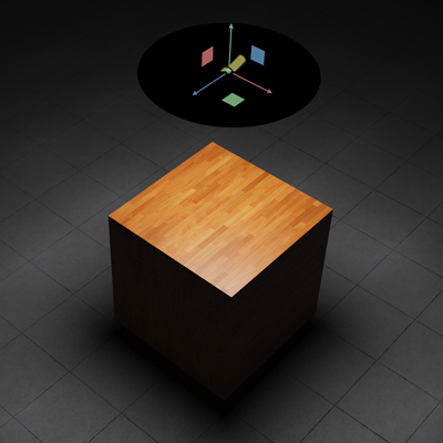
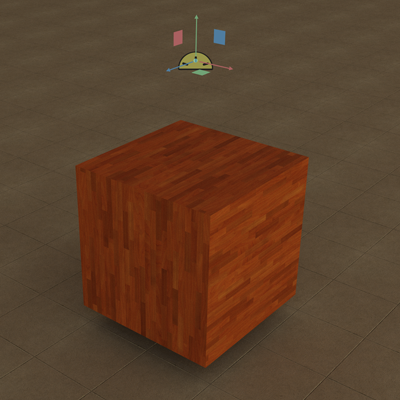
An image projected through a RectLight using the default parameters in the projection_light_texture_generator.py script#
Disk Light#
Similar to the rect light, the Disk light emulates panel lighting, but in the shape of a circle. Size is controlled by radius which affects overall light power as well as shadow softness. If shaping is used, the light acts as a traditional spotlight and has specialized controls to adjust the shape and color of the lights falloff.
Light Specific Properties |
Usage |
|---|---|
Radius |
Radius of the disc. |
Focus |
A control to shape the spread of light. Higher focus values pull light towards the center and narrow the spread. |
Focus Tint |
Off-axis color tint. This tints the emission in the falloff region. The default tint is black. |
Cone Angle |
Angular limit off the primary axis to restrict the light spread. |
Cone softness |
Controls the cutoff softness for cone angle. |
Note
Increasing Shadow samples per pixels in Rendering Settings smooths light falloff at the cost of render speed.
Cylinder Light#
Tubular lighting useful in emulating neon/fluorescent light tubes and other linear omnidirectional lighting.
Light Specific Properties |
Usage
|
|---|---|
Length |
Width of the rectangle, in the local X axis.
|
Radius |
Radius of the cylinder.
|
Dome Light#
Dome Lights are used for image-based (background) lighting when supplied with a texture, and enable you to easily light your entire scene with a high or low dynamic range image.
Light Specific Properties |
Usage |
|---|---|
Texture File |
A color texture to use on the dome, such as an HDR (high dynamic range) texture intended for IBL (image based lighting).
|
Texture Format |
Specifies the parameterization of the color map file.
- automatic: Tries to determine the layout from the file itself. For example, Renderman texture files embed an explicit parameterization.
- latlong: Latitude as X, longitude as Y.
- mirroredBall: An image of the environment reflected in a sphere, using an implicitly orthogonal projection.
- angular: Similar to mirroredBall but the radial dimension is mapped linearly to the angle, providing better sampling at the edges.
- cubeMapVerticalCross: A cube map with faces laid out as a vertical cross.
|
Common Light Properties#
Common Light Properties |
Usage |
|---|---|
Color |
The color of emitted light, in energy-linear terms.
|
Enable Color Temperature |
Enables using color temperature.
|
Color Temperature |
Color temperature, in degrees Kelvin, representing the white point. Lower values are warmer, higher values are cooler.
|
Intensity |
Scales the power of the light linearly.
|
Exposure |
Scales the power of the light exponentially as a power of 2 (similar to an F-stop control over exposure).
The result is multiplied against the intensity.
|
Normalize Power |
Normalizes power by the surface area of the light. This makes it easier to independently adjust the power
and shape of the light, by causing the power to not vary with the area or angular size of the light.
|
Diffuse Multiplier |
A multiplier for the effect of this light on the diffuse response of materials. This is a non-physical control.
|
Specular Multiplier |
Adjusts the amount specularity the light contributes to.
|
Visible In Primary Rays |
Non-physical control to set if the light is visible to the camera or not. If invisible, the global options
/rtx/raytracing/invisLightRefractionsGhostFactorand
/rtx/raytracing/invisLightReflectionsGhostFactor are applied to alos hide highlights of this light. |
Ghost Factor |
Usd setting name
ghostFactor, type float, default -1.Non-physical control to remove a light from reflections and refractions. This overwrites the global options
/rtx/raytracing/invisLightRefractionsGhostFactorand
/rtx/raytracing/invisLightReflectionsGhostFactor when set to any value greater or equal 0.At 0, the light is visible on all materials. At 1, the light will only have an effect on the diffuse layer of materials.
Between 0 and 1, glossy highlights will fade out in their peak intensities.
Note that the per-light factor applies regardless of the primary visibility of the light source.
|
Shaping#
UsdLuxLightShapingAPI is automatically applied to all area lights and adds controls for shaping the distribution of the light source to better match a real source.
Focus#
Focus reduces the brightness of the light that is not parallel to the light’s major axis (-Z), effectively causing the light to become more parallel. This is similar to the effect of an eggcrate grid on a real light source.
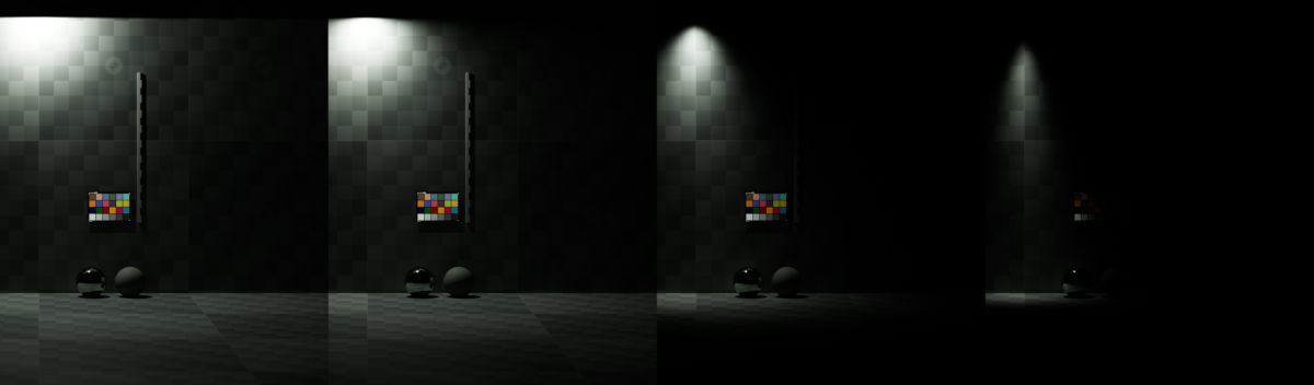
From left to right, inputs:shaping:focus set to 0, 1, 10, 50#
Cone#
Cone Angle and Cone Softness simulate a spotlight. Cone Angle controls the maximum extent of the cone of light, while Cone Softness softens the edges of the cone to simulate the penumbra of a real spotlight.
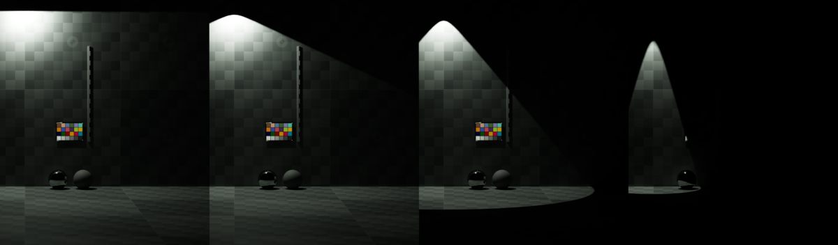
From left to right, inputs:shaping:cone:angle set to 90, 64, 40, 25#
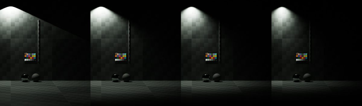
From left to right, inputs:shaping:cone:softness set to 0.0, 0.33, 0.66, 1.0#
Ghost Lights#
Ghost lights replaces the use of the previous Invisible Light Reflections Roughness Threshold and Invisible Light Refractions Roughness Threshold settings by adding a per-light attribute, Ghost Factor to lights to progressively hide them from glossy reflections and transmissions. The global settings have been replaced by Invisible Light Reflections Ghost Factor and Invisible Light Refractions Ghost Factor, respectively. These global settings will be used when a light does not have Ghost Factor authored or its value is set to -1. Scenes using the previous old attributes have their values converted to the new settings automatically.
A ghost factor of 0 has no effect, while a ghost factor of 1 hides the light from all glossy reflections and transmissions, no matter how rough, leaving only diffuse reflection. Higher values between 0 and 1 cause the illumination from the light to be removed progressively, with shinier surfaces being affected first and rougher surfaces being affected last.
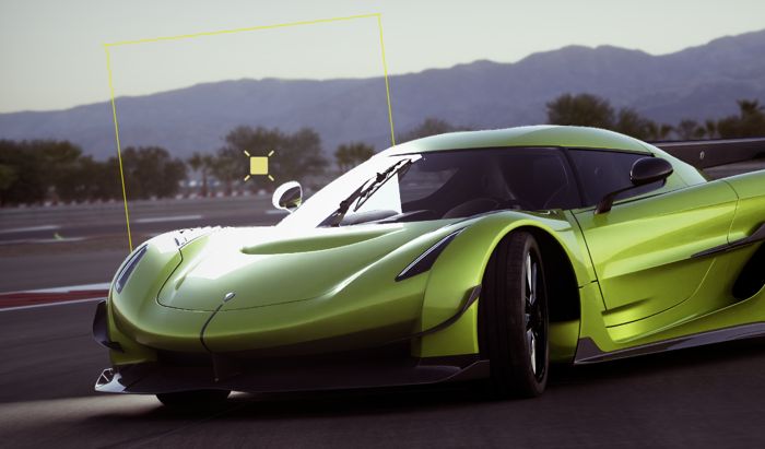
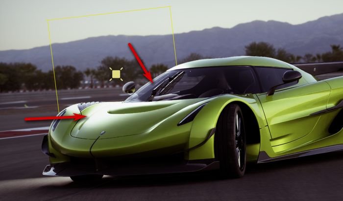
For example, a common workflow is to use lights that are invisible to camera to add extra illumination to a scene for visibility or for beauty lighting. Here, a light has been added directly behind the car to add some extra illumination onto its hood. With the ghost factor defaulting to 0, the light itself is clearly visible in the windshield, both in the reflections and transmission through the glass:
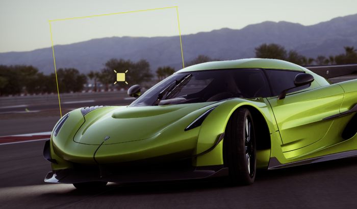
By setting Ghost Factor on the light to a small non-zero value, in this case 0.1, the specular reflections and transmission of the light in the glass and the clear coat are removed, while leaving the glossy reflections in the metallic layers of paint:
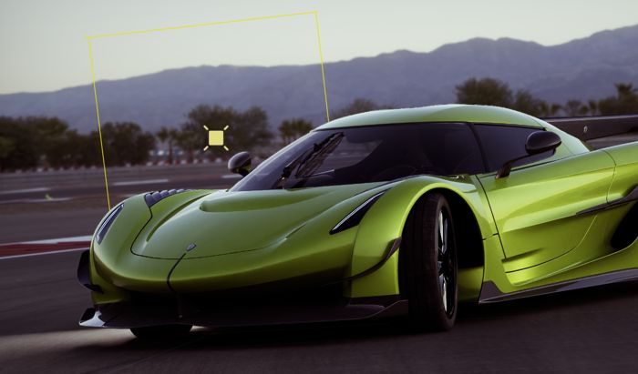
Raising the Ghost Factor further to 0.5 results in the remaining glossy reflections getting further darkened:
Finally, raising Ghost Factor to its maximum of 1.0 results in all glossy reflections of the light being removed, leaving only the diffuse reflections in the car and on the road surface.
Upgrading From Kit 107.3 and Earlier#
Previously, RTX used the Invisible Light Reflections Roughness Threshold and Invisible Light Refractions Roughness Threshold global settings to achieve a similar effect as ghost lights. Existing content using these settings will have these settings converted to Invisible Light Reflections Ghost Factor and Invisible Light Refractions Ghost Factor, respectively, when opened in Kit 108.0 or later.
The look of the new method is similar, but not identical, and existing content may require tweaking to maintain the exact same appearance.
Shaping#
UsdLuxLightShapingAPI is automatically applied to all area lights and adds controls for shaping the distribution of the light source to better match a real source.
Focus#
Focus reduces the brightness of the light that is not parallel to the light’s major axis (-Z), effectively causing the light to become more parallel. This is similar to the effect of an eggcrate grid on a real light source.
From left to right, inputs:shaping:focus set to 0, 1, 10, 50#
Cone#
Cone Angle and Cone Softness simulate a spotlight. Cone Angle controls the maximum extent of the cone of light, while Cone Softness softens the edges of the cone to simulate the penumbra of a real spotlight.
From left to right, inputs:shaping:cone:angle set to 90, 64, 40, 25#
From left to right, inputs:shaping:cone:softness set to 0.0, 0.33, 0.66, 1.0#
IES#
IES files…
Light Linking#
In Omniverse, Lights can be linked to surfaces allowing individualized response to specified lights.
Light linking can be used when very specific control over scene lighting is needed by specifying which lights contribute illumination or shadows to an object.
Property Panel Settings#
Under the Light Link and Shadow Link menus for a light, primitives can be included or excluded. The underlying mechanism for these lists are USD collections. The expansion rules control how primitives are included or excluded from these collections.
explicitOnly - links to one specific primitive
expandPrims - includes the children of the specified primitive
expandPrimsAndProperties - includes children and attributes
Note that these attributes are not currently supported in the light linking paradigm.
The exclude collation can act as a subtraction boolean against the include list. If the expansion rule is set to expandPrims and the top of a hierarchy is selected as s single selection, then the exclude list can be used to remove lower level objects from the include list.
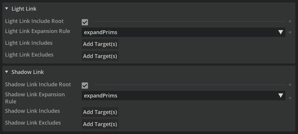
Light Link#
Option |
Result |
|---|---|
Light Link Include Root |
On by default, this includes all objects under the root primitive |
Light Link Expansion Rule |
explicitOnly, expandPrims, expandPrimsAndProperties |
Light Link Includes |
Add Target will bring up a menu to select objects to link to the light |
Light Link Excludes |
Add Target will bring up a menu to select objects to exclude from the light |
Shadow Link#
Option |
Result |
|---|---|
Shadow Link Include Root |
On by default, this includes all objects under the root primitive |
Shadow Link Expansion Rule |
explicitOnly, expandPrims, expandPrimsAndProperties |
Shadow Link Includes |
Add Target will bring up a menu to select objects to link to the light’s shadow |
Shadow Link Excludes |
Add Target will bring up a menu to select objects to exclude from the light’s shadow |
Ghost Factors#
Ghost factors are a non-physical control to remove reflections and refractions of light sources. There are three levels of options to enable all kinds of scenarios:
Globally
Per light
Per object
In general, a value of zero makes the lights fully visible, while a value of one removes them from all but diffuse interactions.
The global factors /rtx/raytracing/invisLightRefractionsGhostFactor and /rtx/raytracing/invisLightReflectionsGhostFactor apply to all invisible light sources (see Visible in Primary Rays).
The per light source factors (usd setting ghostFactor) take precedence over the global ones. They allow fading out highlights regardless of their visibility (e.g., even visible lights can be removed from highlights using a ghost factor greater than zero). Any negative value disables the per light factor.
Lastly, the per object factors (usd setting omni:rtx:ghostFactor) take precedence over both other levels. Any negative value disables the per object factor. Like the global factors, they are sensitive to the lights’ visibility settings. The per object factor only applies to lights that are either invisible or have their own per-light ghost factor configured.
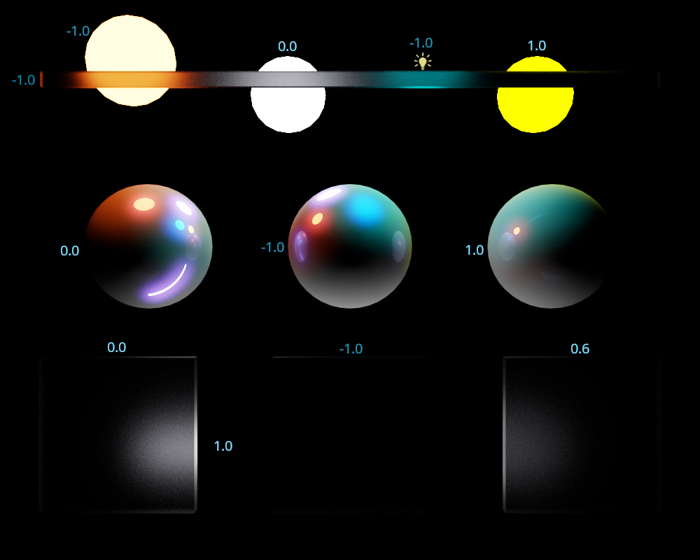
The following image demonstrates different combinations of all factors. The global factors are set to 0.15 for reflections and to 0.8 for refractions. All spheres have a material featuring diffuse, glossy (tinted blue) and specular reflections. Note how the left sphere shows highlights of all five lights, while the other two have several of them removed. At the bottom, there are three rough glass plates in front of an invisible cylinder light with a ghost factor of one.
Physical Lighting#
Omniverse RTX supports specifying lighting in photometric units to make setting up lighting according to real-world measurements or datasheets simple. This behavior is enabled by several schemata, which are provided by the omni.usd.schema.physical_lighting kit extension, which is itself loaded any time RTX is loaded.
How to Add Schemata to Lights
Schemata can be applied using the OpenUSD Python API :
light_prim = stage.GetPrimAtPath("/World/DomeLight")
light_prim.ApplyAPI("PhotometricDomeLightAPI")
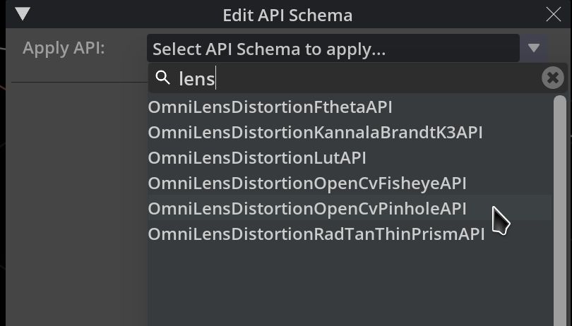
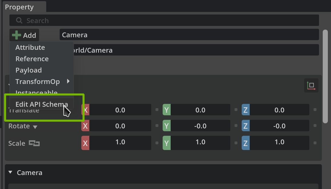
or by using the omni.kit.widget.schema_api extension. The Schema API widget adds functionality for adding a schema to a prim from the Property Window:
Attribute Name |
Type |
Default |
Description |
|---|---|---|---|
|
float2[] |
[] |
An array of (nanometer, radiance) pairs specifying the emission spectrum of the light. The pairs must be ordered such that the wavelength values are monotonically increasing. The wavelengths of the first and last pair in the array define the bounds of the emission range, outside of which emission is zero. The illuminant may be specified at arbitrary intervals, and will be resampled to 5nm intervals according to ASTM-E308. |
|
token |
white |
Allowed tokens: white, blackbody, illuminantD, custom |
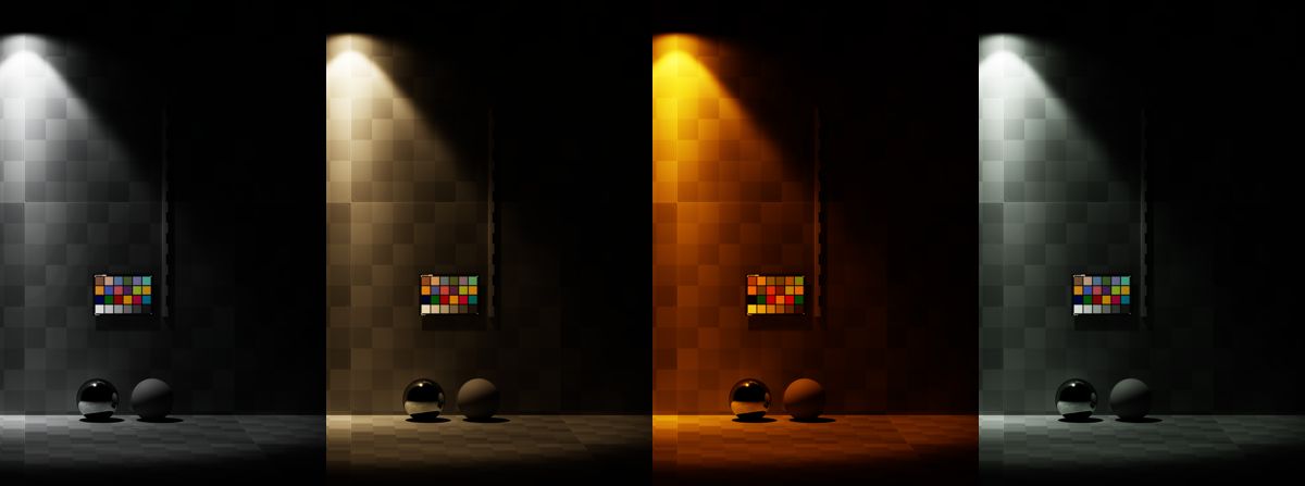
From left to right, “white” illuminant, “illuminant D” at 4000K, “blackbody” at 2000K, “custom” illuminant with CIE F5 distribution#
Attribute Name |
Type |
Default |
Description |
|---|---|---|---|
|
float |
0.0 |
Illuminance received by a surface directly facing the light at ‘photometric:illuminance:distance’ meters. This attribute only has effect when ‘photometric:illuminance:distance’ is non-zero. |
|
float |
0.0 |
When non-zero, the light’s brightness will be such that a surface directly facing the light at this distance, in meters, will receive ‘photometric:illuminance’ lux. |
|
float |
1600.0 |
Photometric power of the light in lumens. |
Attribute Name |
Type |
Default |
Description |
|---|---|---|---|
|
float |
1e+04 |
Illuminance, in lux, received by an upward-facing patch from this light. |
Attribute Name |
Type |
Default |
Description |
|---|---|---|---|
|
float |
1e+04 |
Illuminance, in lux, received by a patch facing perpendicular to this light. |
Inspecting Illuminance Values in a Scene#
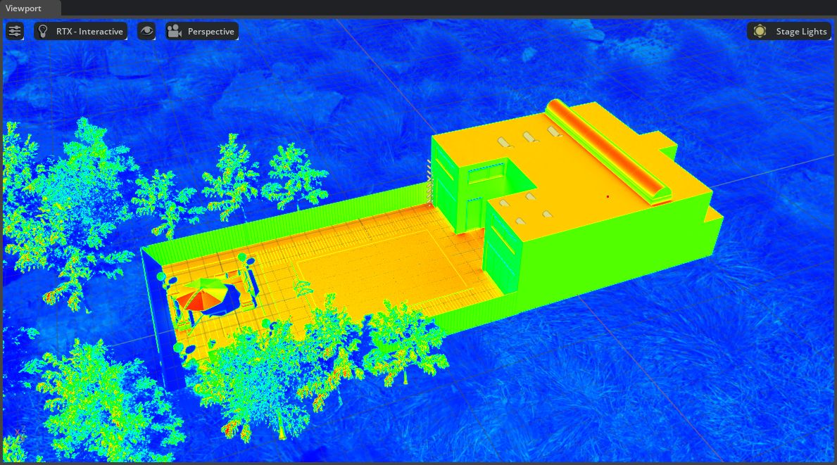
RTX Interactive provides an Illuminance AOV to enable easily inspecting the light levels at different surfaces in a scene. When captured, this AOV will contain absolute illuminance values in lux \((cd/m^2)\). When visualized in Kit, a false color display is applied and values under a pixel can be inspected by clicking on the viewport.
To display the Illuminance AOV in Kit:
first enable
Path Tracing > AOV > Illuminancein the Interactive (Path Tracing) settings: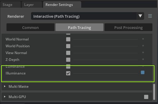
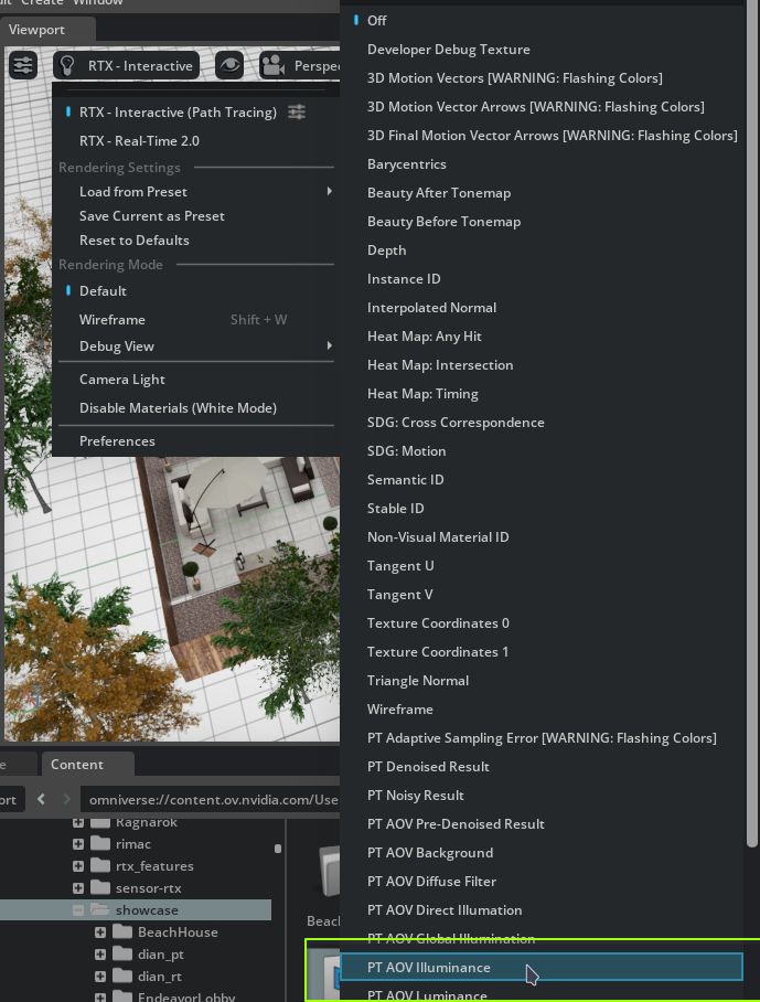
Then switch to the PT AOV Illuminance debug view in the viewport:
The viewport will display the false-color illuminance view:
The illuminance values in the image can be inspected in
Common > View > Debug Viewin the settings window: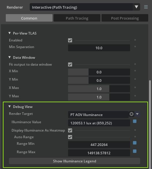
Clicking anywhere on the viewport will display the clicked pixel’s illuminance value in the
Illuminance Valuefield, marking the clicked pixel in red.
Setting Brightness for Area Lights#
The PhotometricAreaLightAPI provides two methods for setting an area light’s brightness.
Power specifies the brightness as photometric power in lumens. This value can commonly be found on lighting datasheets, or on the boxes of household bulbs typically bought at a store. RTX takes account of all attributes of the light source such as color, focus, spotlight controls etc. when calculating power, so the light will always output the specified power regardless of any other effects applied to the light.
The second method is using the photometric:illuminance and photometric:illuminance:distance attributes. When photometric:illuminance:distance is greater than zero, the light will be normalized such that a surface directly facing the light at photometric:illuminance:distance meters will receive photometric:illuminance lux. This is extremely useful for matching any real source that you can measure with an illuminance meter.
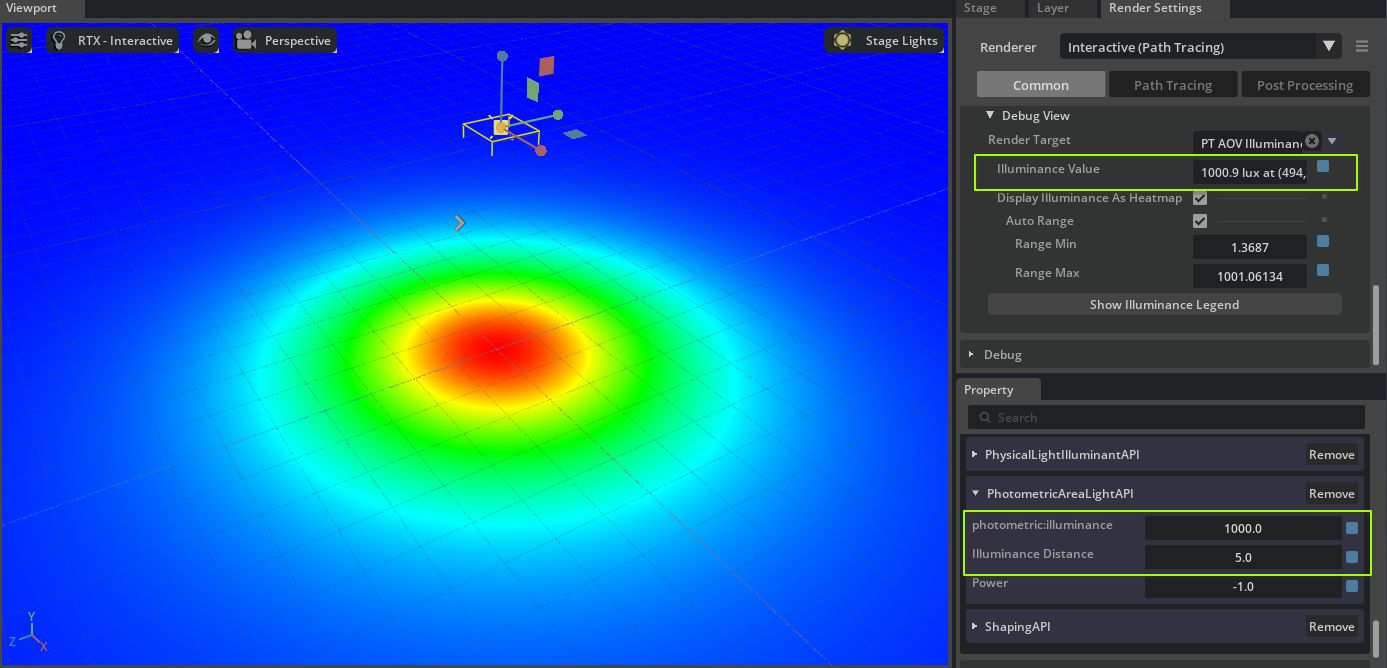
A rect light 5m above a plane showing the correct emission when using the illuminance-at-distance controls#
IES Lights#
IES profiles can be applied to any area light source using the asset inputs:shaping:ies:file attribute. By default, UsdLux does not specify that IES files should be handled photometrically correctly when used with area lights. In order to make lights output the correct brightness according to the IES profile, apply PhysicalIlluminantAPI to the light.
When this schema is applied, RTX will correctly convert from the intensity (candela) values stored in the IES profile to radiance when computing the lighting. Note that when doing this the inputs:intensity attribute on the light will act as a multiplier, so should be set to 1.0 to use the values from the IES profile directly. inputs:intensity may be further modified to model, for example, varying efficacy of the light over time or with temperature.
Note that when PhotometricAreaLightAPI is applied to the light, this overrides the brightness of the light to use units of lumens via the photometric:power attribute, thus this will override the brightness (but maintain the distribution) of any attached IES profile.
Setting Brightness For Dome Lights#
Applying the PhotometricDomeLightAPI to a dome light allows the light’s brightness to be specified in terms of the illuminance, in lux, received at an upward-facing surface due to that light. If using an HDRI to light the scene, this value would be the value measured from an upward-facing illuminance meter when the HDRI was captured. If no such measurement is available, the table below lists some example illuminance values that can be used to derive plausible brightness:
Illuminance (lux) |
Scenario |
|---|---|
0.01 |
Moonlight: quarter moon |
0.25 |
Moonlight: full moon |
10 |
Twilight |
40 |
Sunset: overcast |
400 |
Sunset: clear |
10000 |
Midday: overcast |
20000 |
Midday: shade in clear conditions |
100000 |
Midday: sunlight in clear conditions |
Illuminance (lux) |
Scenario |
|---|---|
4-15 |
Recommended illuminance for roadway illumination |
10-30 |
Recommended illuminance for pavement illumination |
200 |
Public areas, entrance lobbies, public corridors |
300-500 |
Conference rooms, offices |
1000 |
Operation theatre, TV studio, drawing work |
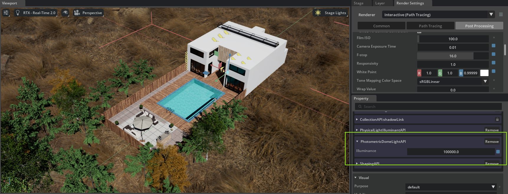
Illuminance of 100000 lux set on a dome light creating a realistic exterior illumination#