


Create Operators#
Operators create dynamic visualizations from scientific datasets. Right-click a dataset prim and select Create > CAE Operators. Operators re-execute when their inputs, fields, time sample, or relevant settings change.
Common Properties#
Every operator exposes these properties in the Properties panel:
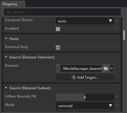
Compute Device:
autouses the global preference. Select a specific device to override it for one operator.Enabled: Disable execution while configuring an expensive operator or diagnosing a pipeline.
Source: The input dataset selected when the operator was created.
The status line reports progress while a long-running operator executes.
Select Fields#
Operator field roles appear as groups such as Colors [Field Selection], Velocities [Field Selection], or Contour [Field Selection].
Select Add Field under Field Name(s).
Select a field from Choose from available fields.
Add more rows when a vector is stored as separate scalar components.
Use Mode to keep the values unchanged, calculate a vector magnitude, or select one component.
Valid, enabled Array Expressions appear in Choose from available fields alongside imported fields.
Field selection no longer targets child field prims. Add Target remains correct for dataset relationships such as Seeds and Region-of-interest (ROI).
Faces#
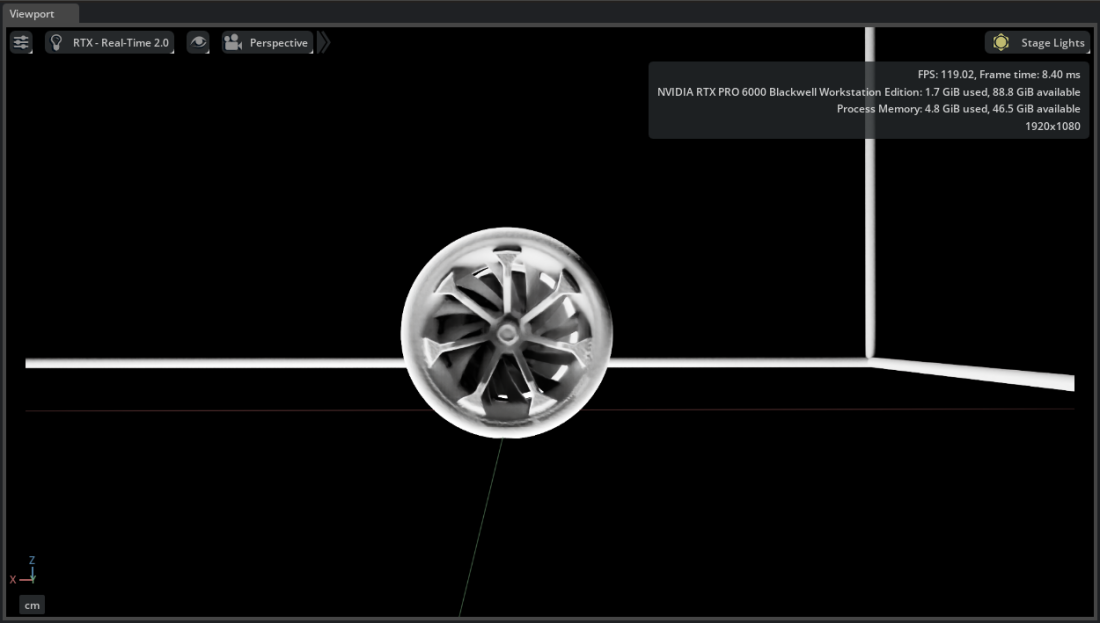
Faces extracts and renders the boundary of a mesh. Use it to show a simulation domain or color a surface by pressure, stress, or another field.
Right-click a dataset and select Create > CAE Operators > Faces.
To color the surface, add a field under Colors [Field Selection].
External Only extracts only the outside boundary when enabled. Disable it to include internal faces. For a polyhedral CGNS model, create Faces from its surface sections instead of extracting faces from the volume section.
Points#
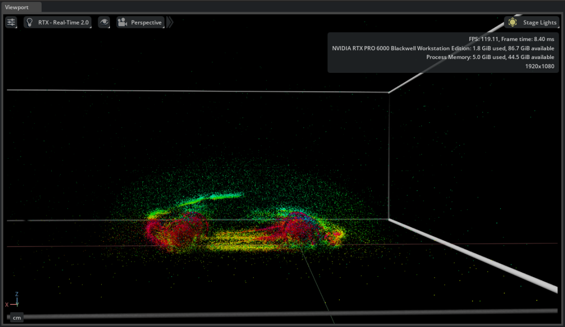
Points renders dataset vertices or point-cloud samples.
Right-click a dataset and select Create > CAE Operators > Points.
Adjust Width to set a constant point size.
Use Colors for scalar coloring or Widths to vary point size from a field.
Max Count limits the rendered samples; set it to 0 to use every point. Use Cell Points excludes isolated points when connectivity is available. Use Points for point clouds or when individual mesh nodes are more useful than a connected surface.
Glyphs#
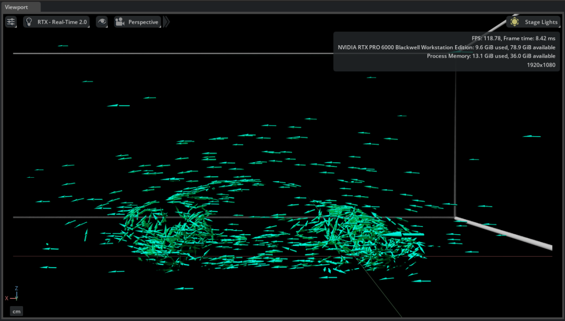
Glyphs places a repeated 3D shape at data points. Choose Sphere, Cone, Arrow, or Custom when creating the operator.
Orientations controls direction. Orientations Mode accepts Euler angles or quaternions.
Scales controls glyph size.
Colors controls scalar coloring.
Max Count limits the number of instances.
Use Cell Points excludes isolated points when connectivity is available.
Streamlines#
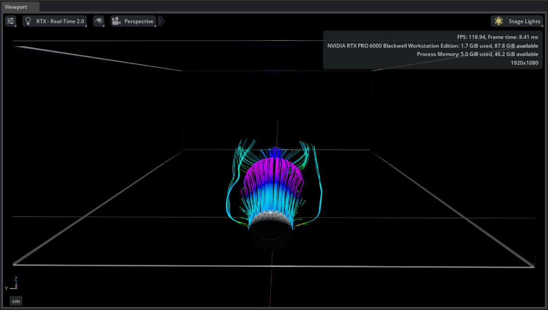
Streamlines traces paths through a vector field from one or more seed datasets.
Create and position a Unit Sphere or other seed geometry.
Right-click the volume dataset and select Create > CAE Operators > Streamlines.
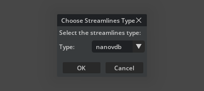
Choose standard for the native mesh or nanovdb to voxelize first.
Under Seeds [Dataset Selection], select Add Target and choose the seed source.
Under Velocities [Field Selection], add the vector field or its scalar components with Add Field.
Use Min Step Size, Max Step Size, Initial Step Size, Max Steps, Direction, Velocity Threshold, Tolerance, and Width to control integration and display.
Volume#
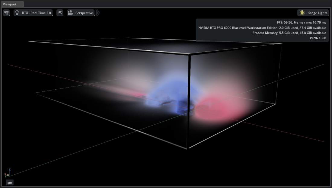
Volume renders scalar data with NVIDIA IndeX.
Right-click a dataset and select Create > CAE Operators > Volume.
Choose a representation:
nanovdb: Voxelizes the input for interactive sparse-volume rendering. It also supports point clouds.
irregular: Preserves supported unstructured cells without voxelization.
Add a scalar field under Colors [Field Selection].
Use nanovdb for most large datasets. Use irregular when preserving the supported source cells is more important than voxelized interaction. Polyhedral cells require nanovdb.
Volume Slice#
Volume Slice creates a renderer-side cross-section of an already processed NVIDIA IndeX Volume. It samples the field selected on that Volume, so configure the Volume first.
Select one Volume prim.
Right-click and select Create > CAE Sources > Volume Slice.
Choose Plane, Bi-Plane, or Tri-Plane.
Translate or rotate the resulting slice geometry to inspect the volume.
Volume Slice appears only when one Volume prim is selected. Although it is in the CAE Sources menu, it is part of the NVIDIA IndeX volume-rendering workflow and does not select a field independently. Its Colormap is initialized from the Volume’s color ramp and can be adjusted separately.
Planar Slices#
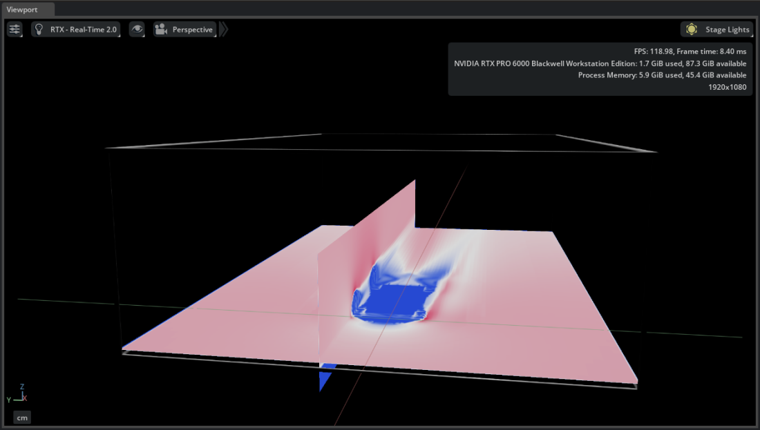
Planar Slices extracts colored triangle geometry directly from the imported dataset. It selects its own color and opacity fields, and does not require a Volume or NVIDIA IndeX.
Right-click a dataset and select Create > CAE Operators > Planar Slices.
Choose standard to slice the native mesh or nanovdb to slice a voxelized representation.
Add a scalar field under Colors [Field Selection].
Set Direction to
x,y,z,xy,xz,yz, orxyz. Usefreefor an arbitrarily oriented plane.
Translate the operator to position every plane. In free mode, rotate the prim so its local +Y axis matches the plane normal.
Use Volume Slice to inspect an existing Volume. Use Planar Slices to work directly from source data.
Iso Surface#
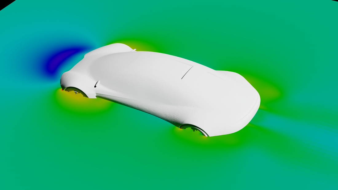
Iso Surface extracts a triangular surface where a scalar field equals an Iso Value. It supports point- and cell-associated contour fields; cell values are averaged to points before extraction.
Right-click a dataset and select Create > CAE Operators > Iso Surface.
Under Contour [Field Selection], add exactly one scalar field.
Set Iso Value to a value inside that field’s range.
Optionally add another scalar field under Colors [Field Selection].
An empty result usually means the iso-value is outside the selected field’s range or the contour does not intersect the dataset.
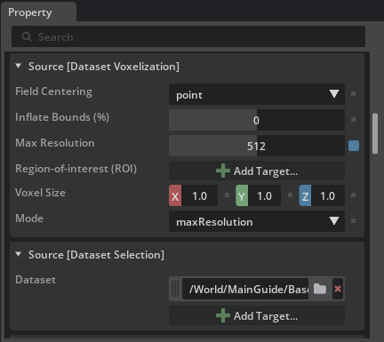
Voxelization Properties#
These properties apply when nanovdb is selected for Streamlines, Volume, or Planar Slices. Flow Dataset Injectors use the same voxelization controls. The values are stored on the operator, so they remain with the stage when it is reopened or shared.
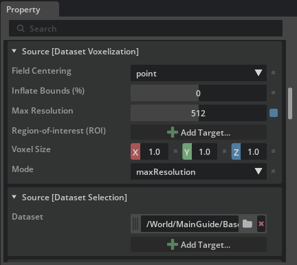
Mode: Choose whether Max Resolution or Voxel Size controls the grid.
Max Resolution: Set the voxel count along the longest axis. This is the recommended starting point when the exact data bounds are not known.
Voxel Size: Set an explicit size along each axis.
Field Centering: Sample fields at grid points or cells.
Region-of-interest (ROI): Select a Bounding Box with Add Target to limit the processed domain.
Inflate Bounds (%): Expand the data or ROI bounds before voxelization.
Dataset Subset#
Non-voxelized mesh operators can expose Source [Dataset Subset]. Select a Bounding Box under Region-of-interest (ROI), then choose how cells are included:
centroid: Keep a cell when its centroid is inside the ROI.
any: Keep a cell when any vertex is inside the ROI.
all: Keep a cell only when every vertex is inside the ROI.
Use Inflate Bounds (%) to expand the ROI before the subset is evaluated.
Try It: Visualize the Vehicle Dataset#
Continue from Try It: Create a Bounding Box and Unit Sphere.
Create Faces#
Select
body_Surface,front_wheels_Surface, andrear_wheels_Surfacein the Stage panel.Right-click and select Create > CAE Operators > Faces.
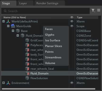
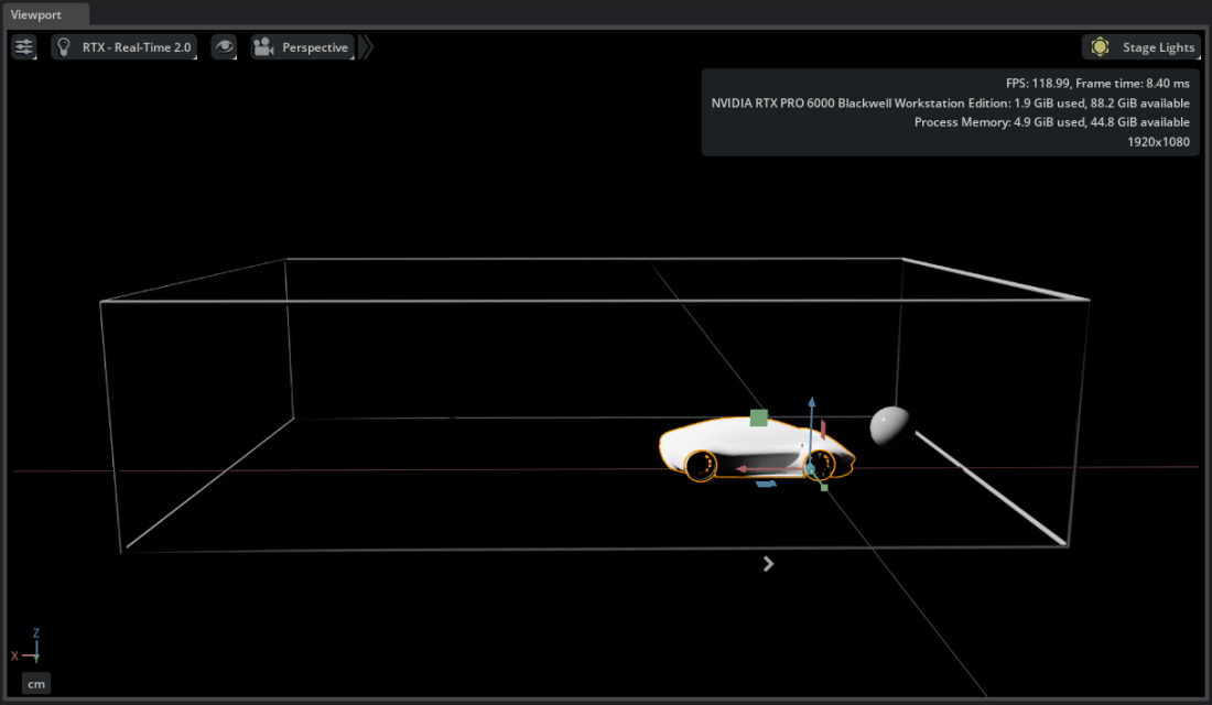
Kit-CAE creates one Faces operator for each selected surface under /World/CAE.
Create Streamlines#
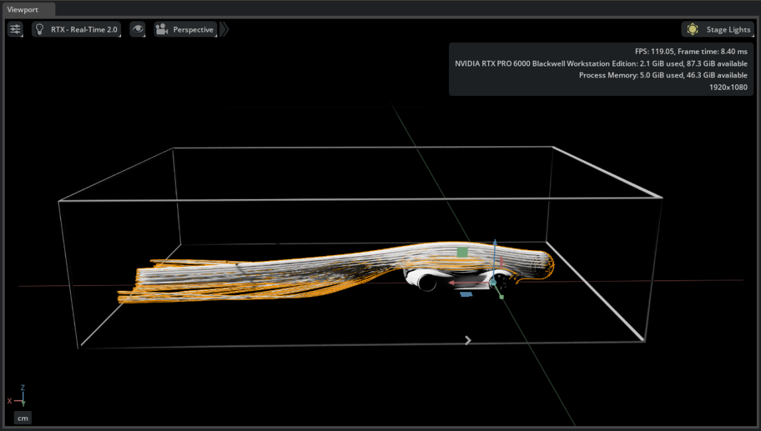
Right-click the volume dataset named
Fluid_Domainand select Create > CAE Operators > Streamlines.Choose nanovdb.
Select the new Streamlines prim and set Direction to
forward.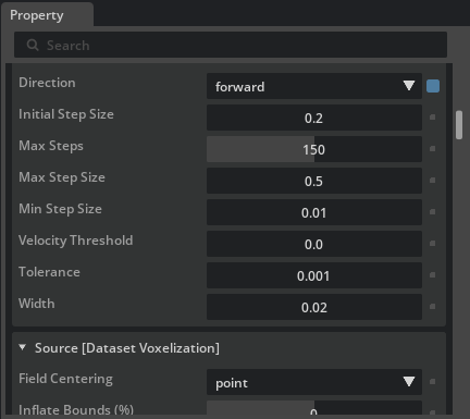
Under Seeds [Dataset Selection], select Add Target and choose the Unit Sphere.
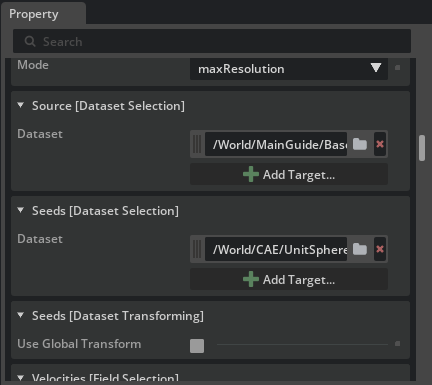
Under Velocities [Field Selection], add
Velocity_0,Velocity_1, andVelocity_2with Add Field.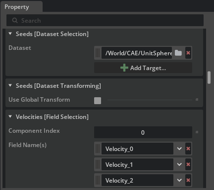
Move the Unit Sphere to explore flow paths from another region.
Create a Volume#
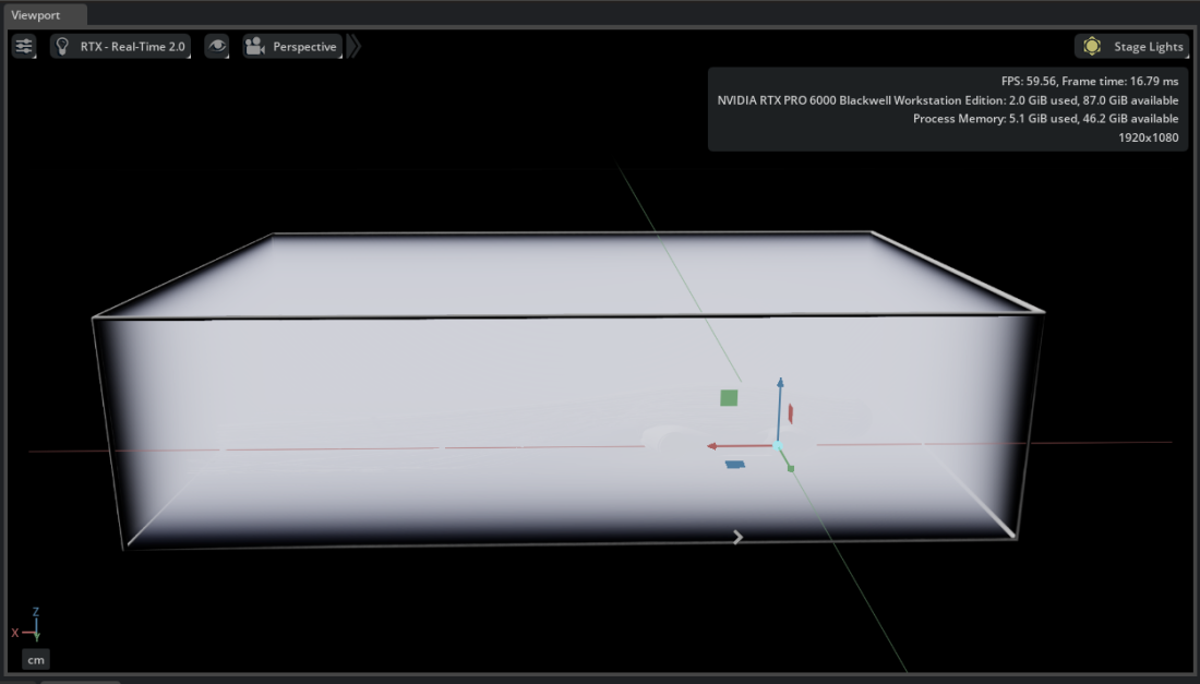
Right-click
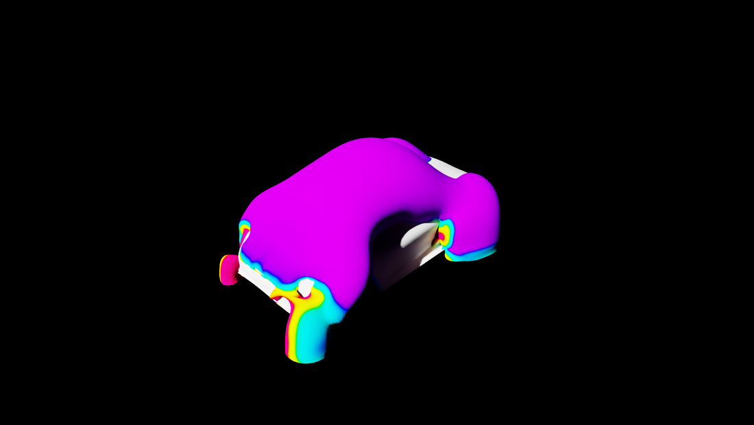
Fluid_Domainand select Create > CAE Operators > Volume. Choose nanovdb.Under Source [Dataset Voxelization], set Max Resolution to
512.
Under Colors [Field Selection], add all three velocity components and set Mode to
vector_magnitude.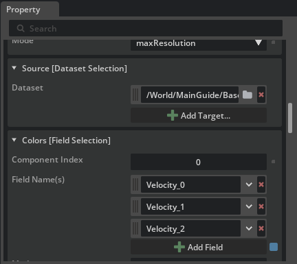
Create Planar Slices#
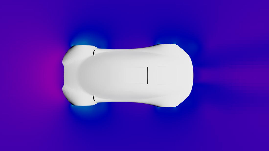
The Volume above visualizes velocity magnitude from Fluid_Domain. Create Planar Slices as a separate pressure view of that same imported dataset. The slices read Fluid_Domain directly; they do not read from or depend on the Volume.
Right-click
Fluid_Domainand select Create > CAE Operators > Planar Slices.Choose standard to slice the native CGNS mesh. The nanovdb option would voxelize the dataset before slicing it.
Under Colors [Field Selection], add
Pressure.Set Direction to
zand move the operator to approximatelyZ = 0.6. The horizontal plane intersects the pressure field at mid-body height.
Continue to Try It: Tune the Color Mapping to refine these visualizations.
Use the Stage panel visibility icon  to show or hide an operator without changing its configuration.