


Color Mapping and Rendering#
Color mapping converts scientific values into colors. Select the values on the operator, then adjust the material or Colormap that renders the result.
Select a Color Field#
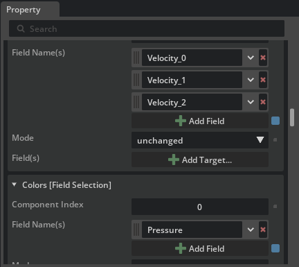
Use Colors [Field Selection] on an operator:
Select Add Field under Field Name(s).
Choose a scalar field, a vector-valued field, or several scalar components.
Set Mode:
unchangedkeeps the selected values.vector_magnitudecalculates one scalar magnitude from vector components.selected_componentuses Component Index from a vector.
Use unchanged for a scalar field such as pressure or temperature. For a vector stored as one (N, 3) array or as three separate scalar components, use vector_magnitude to color by magnitude. Use selected_component to color by one component of a vector-valued field. Adding a valid color field enables scalar coloring automatically.
Materials and Colormaps#
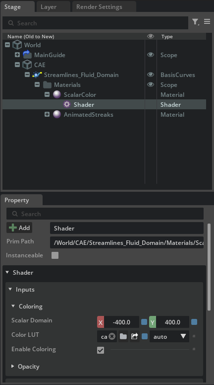
Surface operators such as Faces, Points, Glyphs, Iso Surfaces, Streamlines, and Planar Slices create an NVIDIA Material Definition Language (MDL) material below the operator. Select its Shader prim to edit:
domain: The numeric interval mapped to the lookup table
lut: The lookup-table texture
Kit-CAE includes afmhot, cividis, gist_gray, and gist_rainbow lookup-table textures.
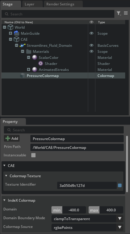
Volume and Volume Slice operators use a Colormap prim. Its color and opacity control points define the transfer function. Domain Boundary Mode controls values outside the domain:
clampToEdgeuses the nearest endpoint color.clampToTransparentmakes out-of-range values transparent.
You can also create a reusable Colormap with Create > CAE Sources > Colormap.
Control Automatic Rescaling#
Operators initialize material ranges from the selected field. Use Rescale Mode for the colors selection to control later updates:
clampsets the range to the current field range.growexpands the range when later values fall outside it.disablepreserves a manually authored range.
Set disable before authoring a fixed domain or Colormap range.
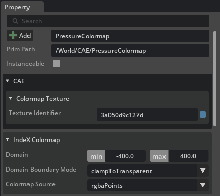
You can also lock an individual property. Set the value, right-click its field, then select Locks > Lock. Unlock it when the operator should update the value again.
Map Opacity from a Field#
Kit-CAE supports an independent opacity field on Faces, Points, Glyphs, Iso Surfaces, Streamlines, and Planar Slices.
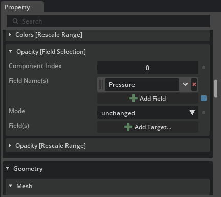
Under Opacity [Field Selection], add one scalar field with Add Field.
Select the operator’s Shader prim.
Adjust Opacity Domain, Opacity LUT, and the Opacity multiplier.
Set the opacity Rescale Mode to
disablewhen using a fixed domain.
Color and opacity can use different fields and lookup tables. A Colormap source publishes both its color ramp and the opacity values from its alpha control points.
Try It: Tune the Color Mapping#
Continue from Try It: Visualize the Vehicle Dataset.
Volume#
Select the Volume operator. Confirm that Colors contains the three velocity components and Mode is
vector_magnitude.Set the colors Rescale Mode to
disable.Expand the Volume to Material > Colormap. Set Domain to
0through30.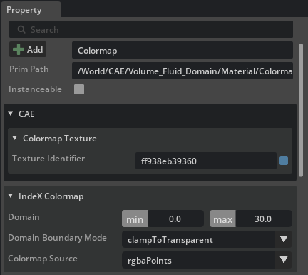
Set Domain Boundary Mode to
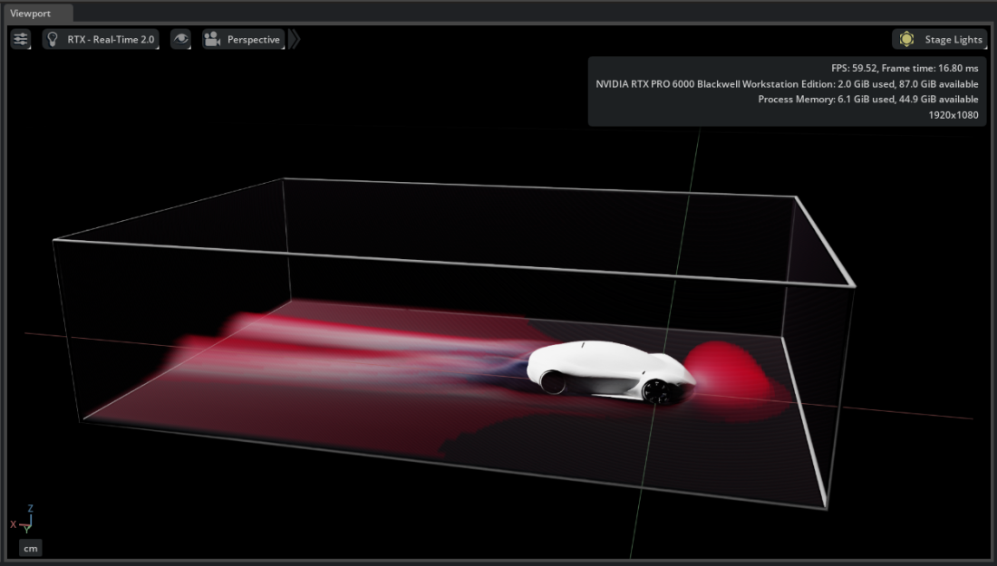
clampToTransparentand adjust the opacity control points to reveal the wake.
Planar Slices#
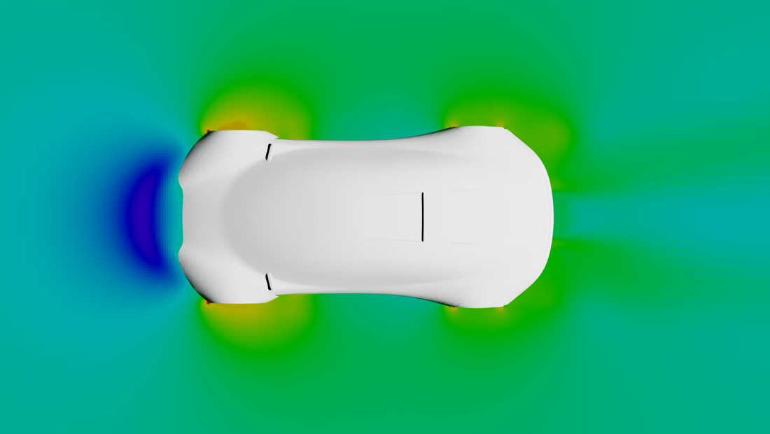
Continue with the independent Planar Slices created directly from Fluid_Domain in the previous section.
Hide the Volume and show the Planar Slices operator.
On the Planar Slices operator, confirm that Colors contains
Pressureand set the colors Rescale Mode todisable.Select Materials > UnlitScalarColor > Shader and set domain to
-400through400. Leavegist_rainbowselected or choose another lut.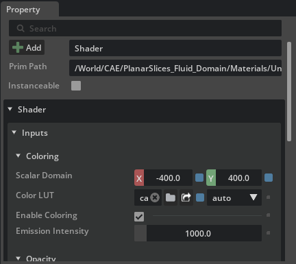
Streamlines#
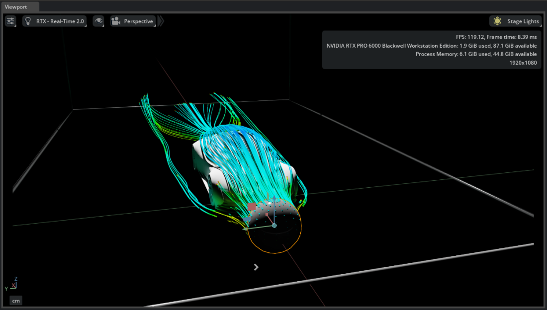
Show the Streamlines and Faces operators. Hide other visualizations.
On Streamlines, add
Pressureunder Colors [Field Selection] and leave Mode set tounchanged.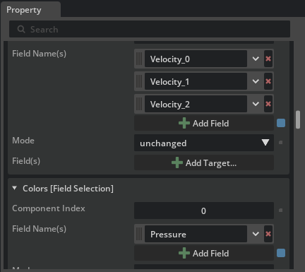
Set the colors Rescale Mode to
disable. Select Materials > ScalarColor > Shader, set domain to-400through400, and choose a lut.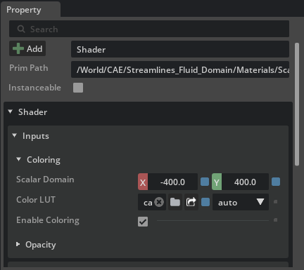
Move the Unit Sphere. Streamlines recompute from the new seed positions while the fixed color domain remains unchanged.
Try Field-Driven Opacity#
Hide Streamlines and show the Planar Slices operator again.
Under Opacity [Field Selection], add
Velocity_0,Velocity_1, andVelocity_2. Set Mode tovector_magnitudeand the opacity Rescale Mode todisable.On Materials > UnlitScalarColor > Shader, set Opacity Domain to
0through30. Use Opacity LUT to control how values within that range fade, and use Opacity as an overall multiplier.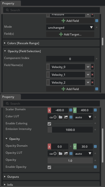
Color continues to use Pressure and its -400 through 400 domain. Opacity now uses velocity magnitude and its independent 0 through 30 domain.