Multi-Domain Simulation#
This example imports two solver outputs into the same USD stage: a volumetric pressure field represented as a point cloud around a wing, and bending stress on the wing surface. Both datasets share a common time range. Scrubbing the timeline animates both in sync, showing the pressure field in the flow volume alongside the structural stress response on the wing itself.
The two datasets use different formats (CGNS and EnSight). Kit-CAE imports both without conversion and without requiring that they come from the same solver or file format.
Note
This example requires sample data. If you have not already downloaded it, see Examples for the download link.
Dataset#
The data is derived from unsteady URANS CFD results on the BSCW (Benchmark Supercritical Wing) at M = 0.74, Re = 4.49 × 10⁶, computed under prescribed pitch/plunge motion.
File |
Format |
Field |
Description |
|---|---|---|---|
|
CGNS |
Cp |
Pressure coefficient at 4,991 volume nodes (point cloud around the wing) |
|
EnSight Gold |
BendingStress |
Bending stress on the wing surface (derived from the original surface pressure) |
Time: 101 time steps
Source attribution and license details are included with the downloaded data.
Import the Data#
Kit-CAE reads directly from each solver’s native format. In this example you import an EnSight Gold file (structural) and a CGNS file (CFD) into the same USD stage without converting either one.
Note
This walkthrough assumes you have already built Kit-CAE. If not, see Get Started for setup instructions.
Launch Kit-CAE.
On Linux:
./repo.sh launch -n omni.cae.kit
On Windows:
repo.bat launch -n omni.cae.kit
Import the Structural Data#
Click File > Import and navigate to:
{path to}/kit_cae_user_guide_data/examples/03_multi-domainSelect
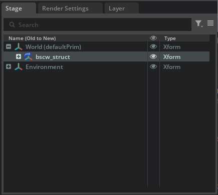
bscw_struct.case. Check Import to Stage and click Import.The
/World/bscw_structprim appears in the Stage panel.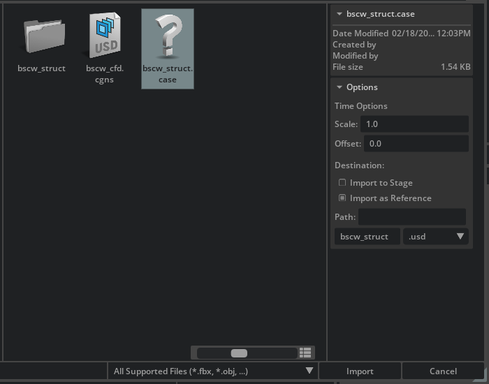
Import the CFD Data#
Click File > Import again and select
bscw_cfd.cgnsfrom the same folder.Check Import to Stage and click Import.
The
/World/bscw_cfdprim appears in the Stage panel alongside the structural data.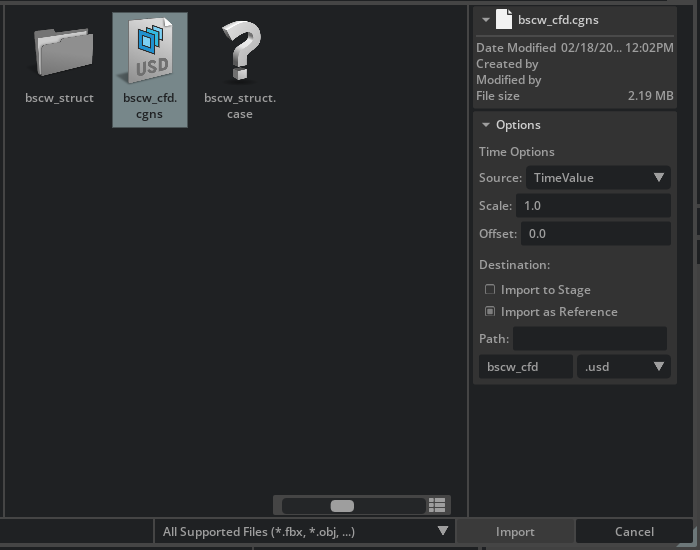

Note
Nothing appears in the viewport yet. Both datasets are loaded into the stage, but you have not created any visual representations.
Visualize Wing Movement#
Start by creating a surface representation of the wing from the structural dataset.
In the Stage panel, expand
bscw_structto/World/bscw_struct/bscw_struct_case/wing_surface.Right-click
wing_surfaceand select Create > CAE Operations > Faces.A new prim (
/World/CAE/Faces_wing_surface) appears in the Stage panel and a gray wing mesh appears in the viewport.Press the Play button on the left sidebar (or press Space) to animate the simulation. You can also drag the timeline to scrub through individual frames.

Note
The first time you play or scrub through a transient dataset, each frame must be cached before it will play back smoothly in the viewport. Scrubbing the full timeline is the most efficient way to build this cache. Subsequent playback will be smooth.
Tip
Press F with an object selected to focus the camera on it.
Visualize Volume Results#
Next, create a volume representation of the CFD pressure field around the wing.
Hide the wing surface by clicking the eye icon next to
/World/CAE/Faces_wing_surfacein the Stage panel.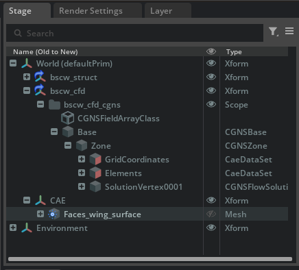
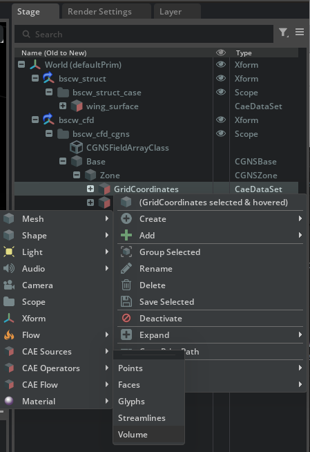
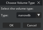
Expand the CFD dataset to
/World/bscw_cfd/bscw_cfd_cgns/Base/Zone/GridCoordinates. Right-clickGridCoordinatesand select Create > CAE Operations > Volume.When prompted to choose a volume type, select nanovdb.
Nothing appears in the viewport yet because no field has been assigned.
Select
/World/CAE/Volume_GridCoordinatesin the Stage panel. In the Property panel, scroll to the Source [Gaussian Splatting] section and set Radius Factor to 8.0.Still in the Property panel, scroll to Colors [Field Selection] and click Add Target. In the popup, navigate to
/World/bscw_cfd/bscw_cfd_cgns/Base/Zone/SolutionVertex0001/Cpand click Select.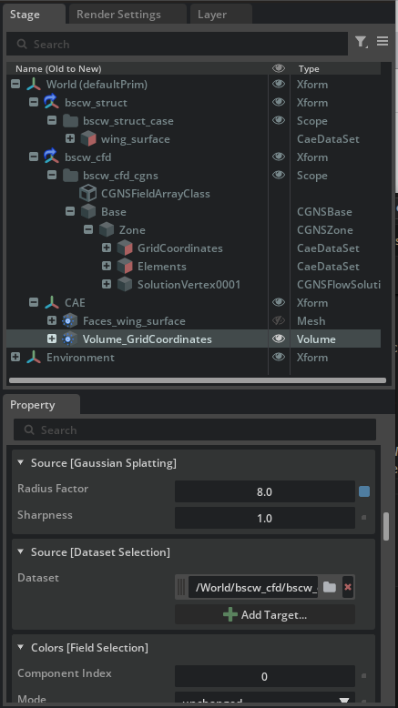


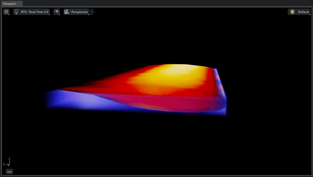
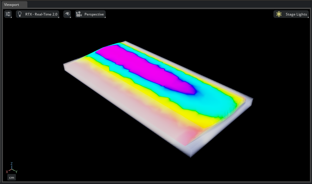
The viewport now shows the pressure coefficient field as a volume around the wing.

Bring the Domains Together#
The pressure applied by the flow field induces a stress response on the wing. In this section you combine both visualizations and color the wing by bending stress to see the structural response alongside the aerodynamic loading.
Restore visibility of the wing by clicking the eye icon next to
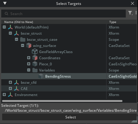
/World/CAE/Faces_wing_surfacein the Stage panel.With
/World/CAE/Faces_wing_surfaceselected, scroll to Colors [Field Selection] in the Property panel and click Add Target. In the popup, navigate to/World/bscw_struct/bscw_struct_case/wing_surface/Variables/BendingStressand click Select.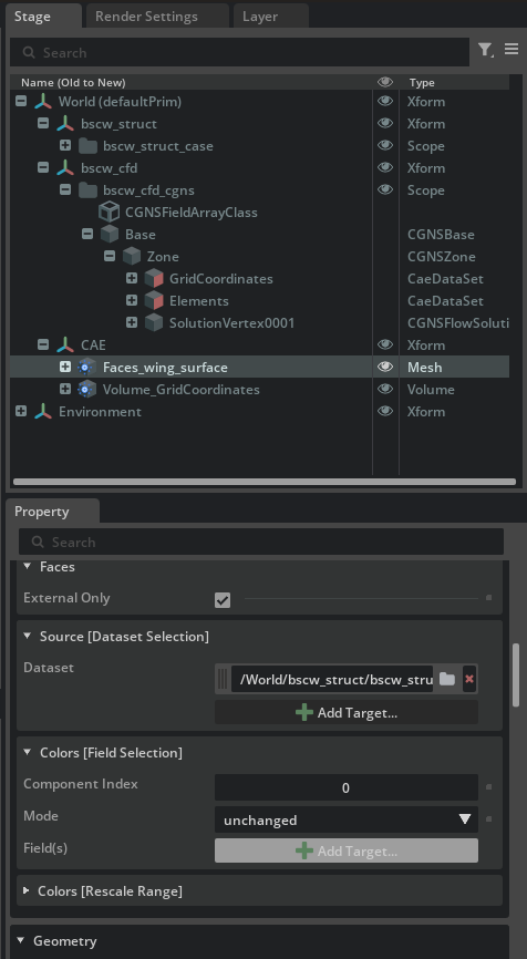
Scrub the timeline or press Play to see the bending stress on the wing and the pressure volume change together.
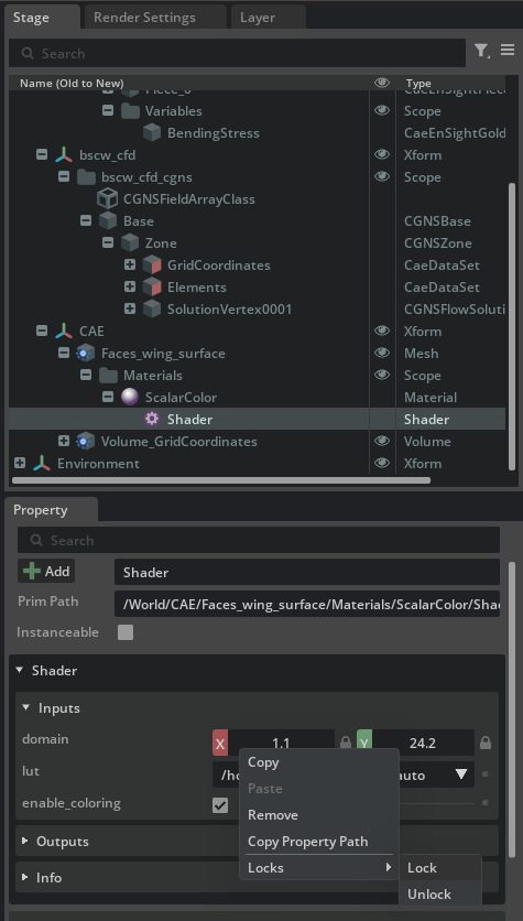
By default the color range on the wing updates at each frame. To lock it, navigate to
/World/CAE/Faces_wing_surface>Materials>ScalarColor>Shaderin the Stage panel. Right-click the domain fields, select Locks, then select Lock. Scrub or play the timeline again to confirm the range stays fixed.