


Simulation Data in Context#
This example composes a steady-state thermal simulation with a detailed NVIDIA GB300 NVL72 server-rack model. The CGNS field data and Universal Scene Description (USD) geometry remain in their native files while OpenUSD presents them in one stage.
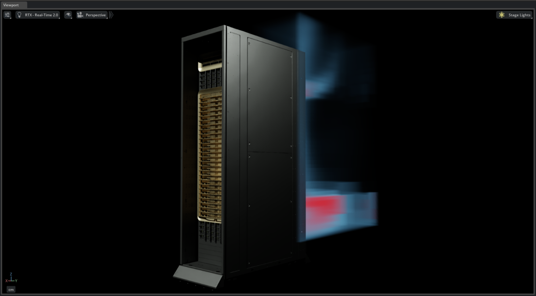
The thermal data is inspired by the type of analysis in the NVIDIA Omniverse™ Blueprint for AI Factory Digital Twins. It covers the region near one rack and retains the influence of the surrounding environment.
Note
This example requires the sample data described in Examples. If you have not built Kit-CAE, see Get Started first.
Dataset#
Use the files in:
{path to}/kit_cae_user_guide_data/examples/02_simulation-data-in-context
compute_thermal.cgnscontains a cell-associatedTemperaturefield on approximately 71,500 nodes and 57,100 hexahedral elements.GB300.usdcontains the GB300 NVL72 server-rack geometry.
Import the Data#
Launch Kit-CAE.
Linux:
./repo.sh launch -n omni.cae.kitWindows:
repo.bat launch -n omni.cae.kitSelect File > Open and open
GB300.usd. The rack appears in the Viewport.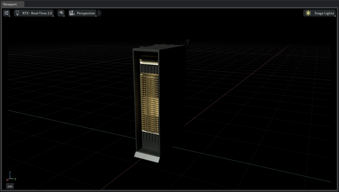
Select File > Import, select
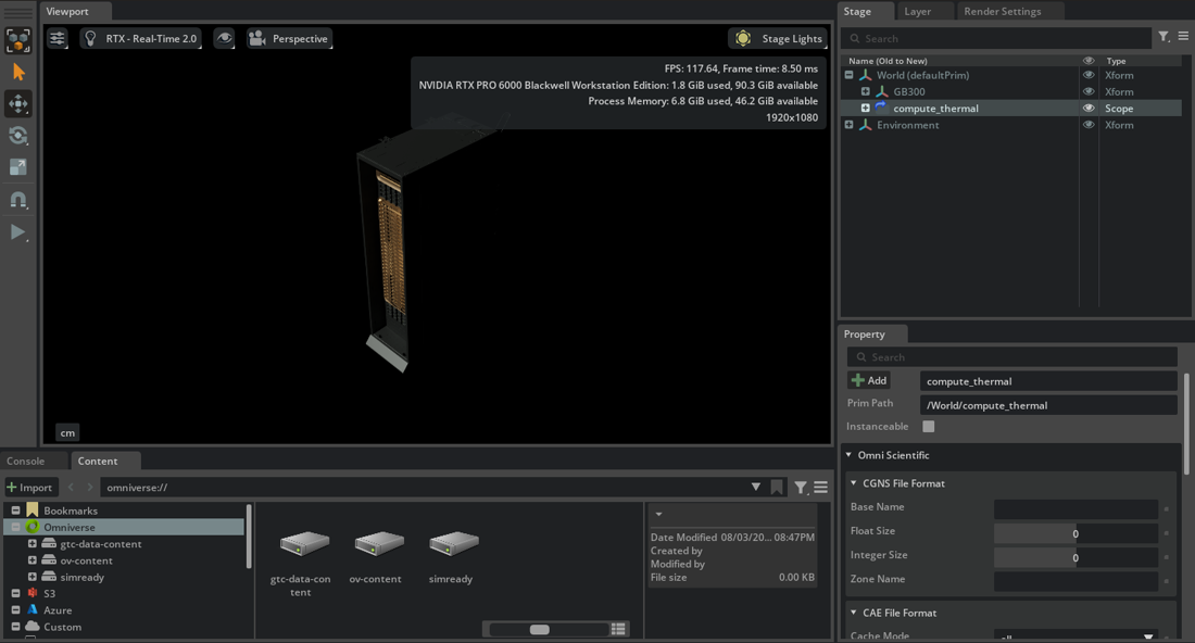
compute_thermal.cgns, enable Import to Stage, and select Import.
The imported CGNS hierarchy appears in the Stage panel. Nothing new is visible until you create an operator.
Create a Region of Interest#
Expand the thermal data to
Base > Zone > Elements.Right-click
Elementsand select Create > CAE Sources > Bounding Box.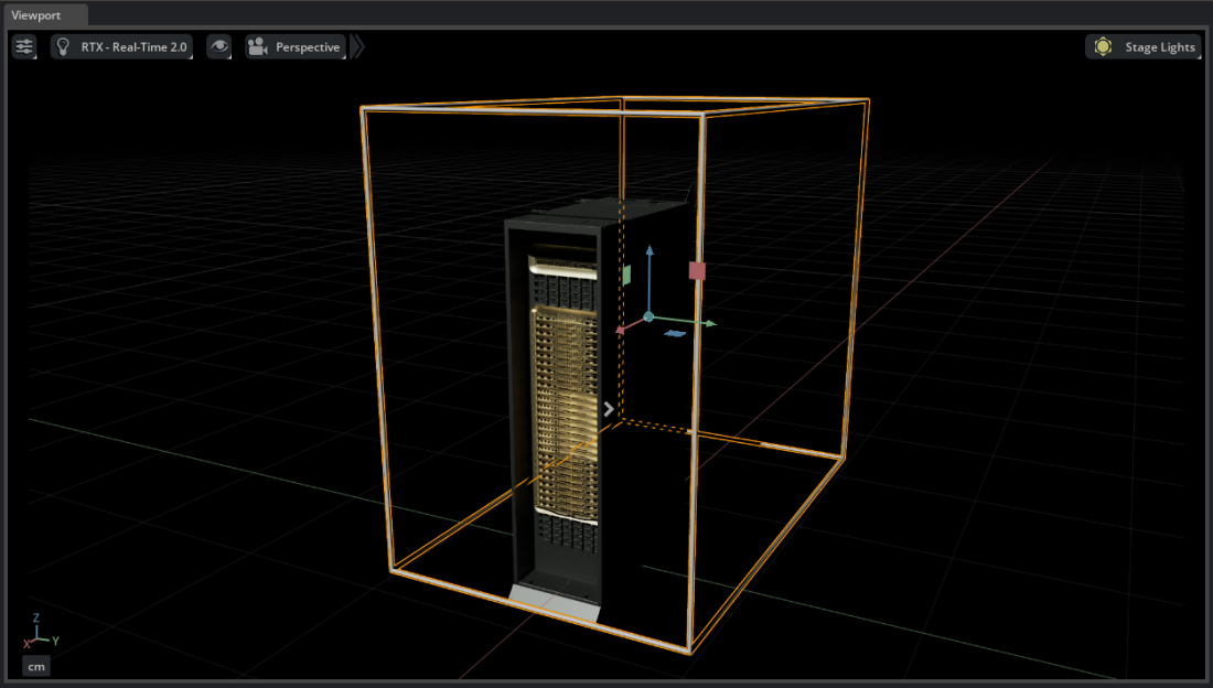
Duplicate the Bounding Box with Ctrl+D.
Press R to scale the duplicate and W to translate it. Fit it around the hot-aisle region directly behind the rack.
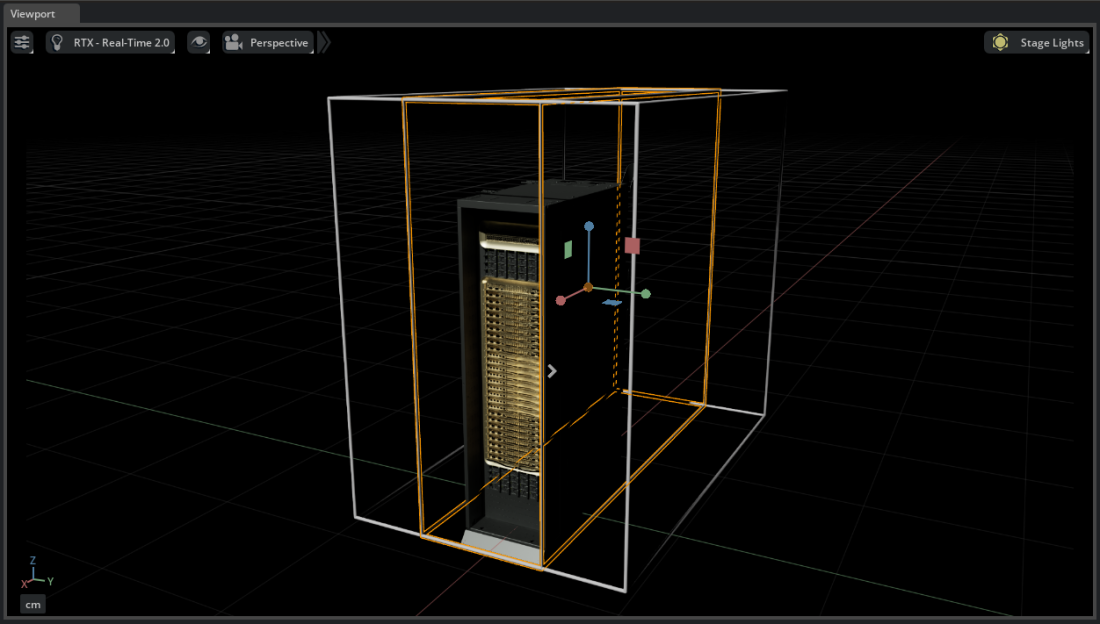
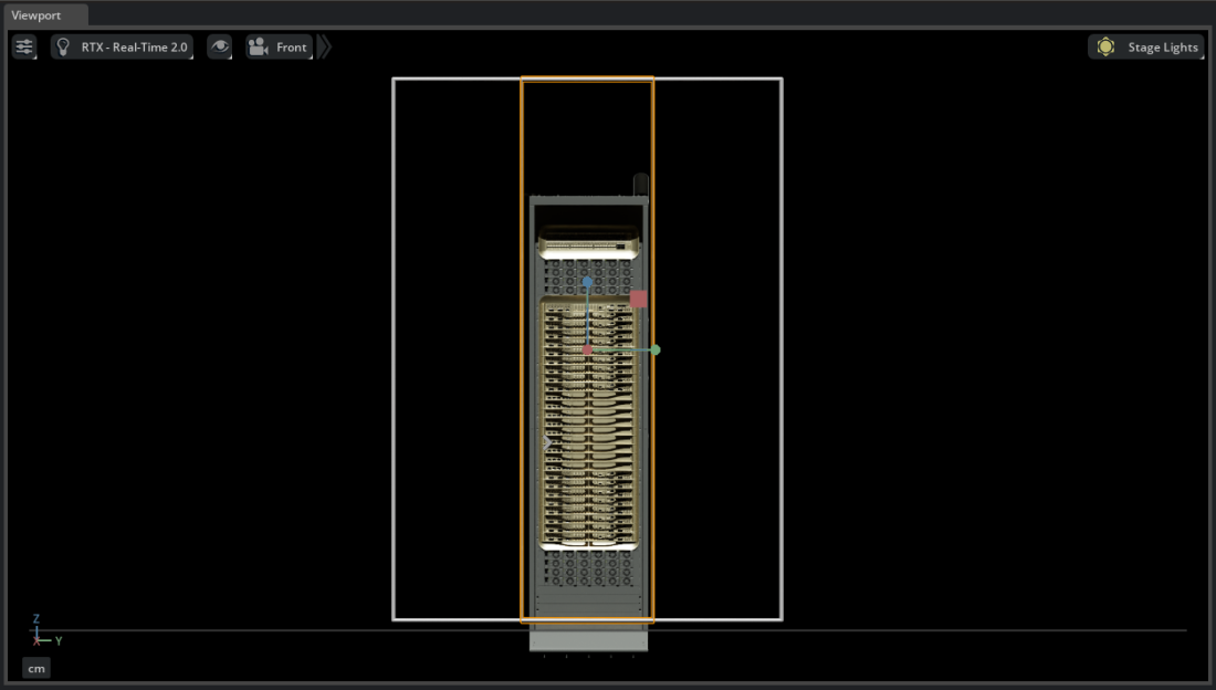
The boxes are standalone USD prims after creation. The full box remains a reference for the simulation extent, and the smaller box becomes the region of interest.
Create the Thermal Volume#
Right-click
Elementsand select Create > CAE Operators > Volume. Choose nanovdb.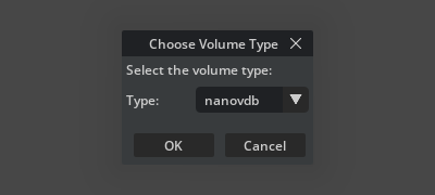
Under Source [Dataset Voxelization], select Add Target for Region-of-interest (ROI) and choose the smaller Bounding Box.
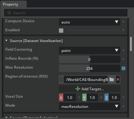
Set Max Resolution to
256. Increase it later if the region needs more detail.Under Colors [Field Selection], use Add Field to select
Temperature.The thermal field appears around the rack with the default coloring.
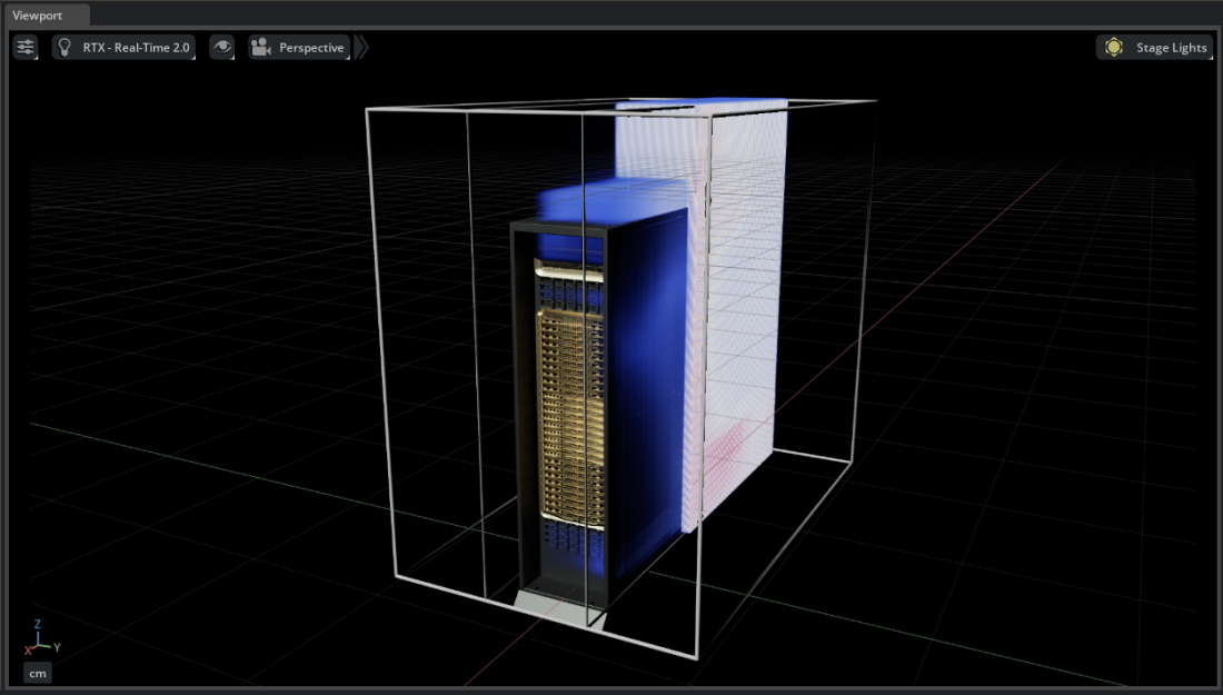
Set the colors Rescale Mode to
disable.Expand Material > Colormap and set the domain to approximately
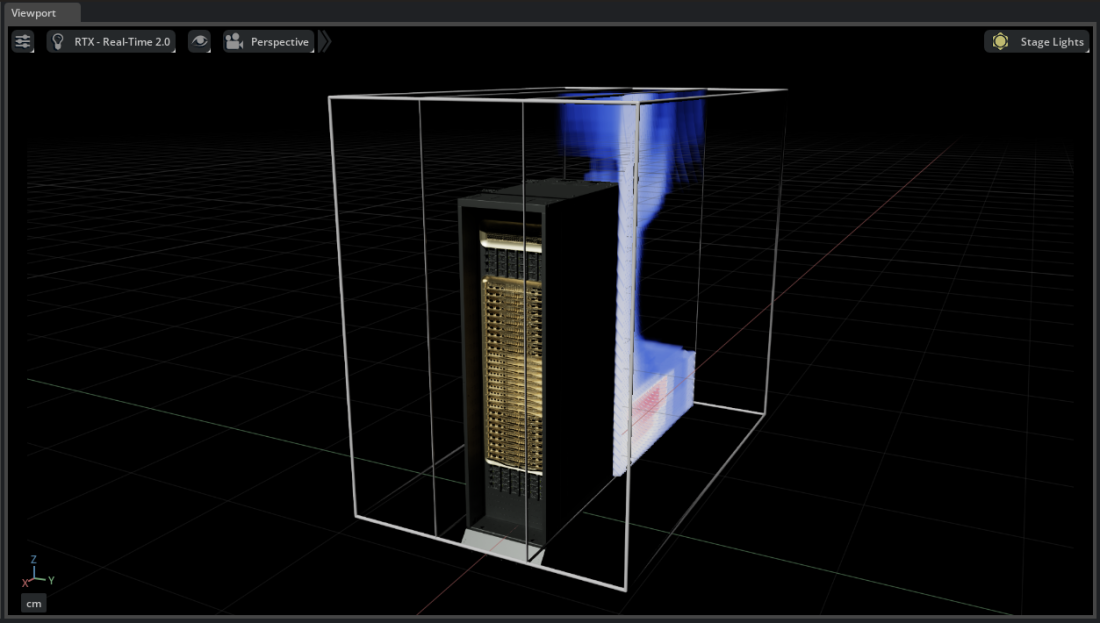
31through37to focus on the hotter air near the rack. Adjust the transfer function for the desired transparency.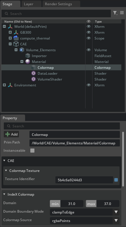
Toggle the rack visibility to inspect the field alone, then show it again to interpret the thermal result in context.
Note
irregular volume mode preserves supported unstructured cells without voxelization. Use it when cell-level detail is more important than interactive resampling performance.