Flow Visualization#
CAE Flow provides particle-based animated flow visualization. It uses NVIDIA Flow, a GPU-accelerated particle simulation and volume rendering engine, to animate particles along paths derived from velocity fields. Use Flow when you want an intuitive, animated view of how fluid moves through the domain. It produces a smoke-like effect that reveals flow direction, recirculation, and turbulence patterns. Flow is ideal for exploring complex 3D flow structures and communicating results to non-technical stakeholders. For more precise visualization of flow patterns, use the Streamlines operator instead.
CAE Flow is separate from the operator system. To access it, right-click a dataset prim in the Stage panel and navigate to Create > CAE Flow.
Create a Flow Environment#
The flow environment is the container for all flow visualization elements. Flow simulations can run on multiple layers; when the layer prompt appears, use layer 0 unless you have a specific reason to separate layers.
In the Stage panel, right-click on a dataset node.
Navigate to Create > CAE Flow > Environment.
A
FlowSimulateprim is created.
Create a Fuel Injector Sphere#
The fuel injector sphere controls where flow particles are emitted. Like the Unit Sphere used for streamlines, you can move it around the domain to explore flow behavior from different positions.
Right-click on the dataset node and select Create > CAE Flow > Fuel Injector Sphere.
A new emitter sphere prim is created under
/World/CAE/.
Create a DataSet Injector#
The dataset injector connects the flow visualization to your simulation data. It defines which fields drive the particle behavior.
Right-click on the dataset node and select Create > CAE Flow > DataSet Injector.
A new injector prim is created.
In the injector’s properties, configure the data targets:
Next to Velocity, click Add Target and select the velocity field components.
Next to Temperature, click Add Target and select a scalar field
Starting the Flow#
To see the flow animation, either:
Check Force Simulate on the
FlowSimulateprim in the Property panel, orPress the Play button on the timeline.
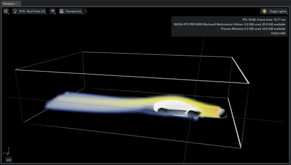
Try It: Animate Flow Around the Vehicle#
In the previous Try It you tuned the color mapping. Now create an animated flow visualization using the same vehicle dataset.
Hide all operators and sources from previous steps. Show only the Faces operators so you can see the vehicle body for context.
Right-click
/World/auto_aero_solver_result/auto_aero_solver_result_cgns/Base/Fluid_Domain/Fluid_Domainand select Create > CAE Flow > Environment. When prompted to select a layer, use 0.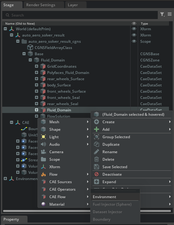
Right-click
Fluid_Domainagain and select Create > CAE Flow > Fuel Injector Sphere.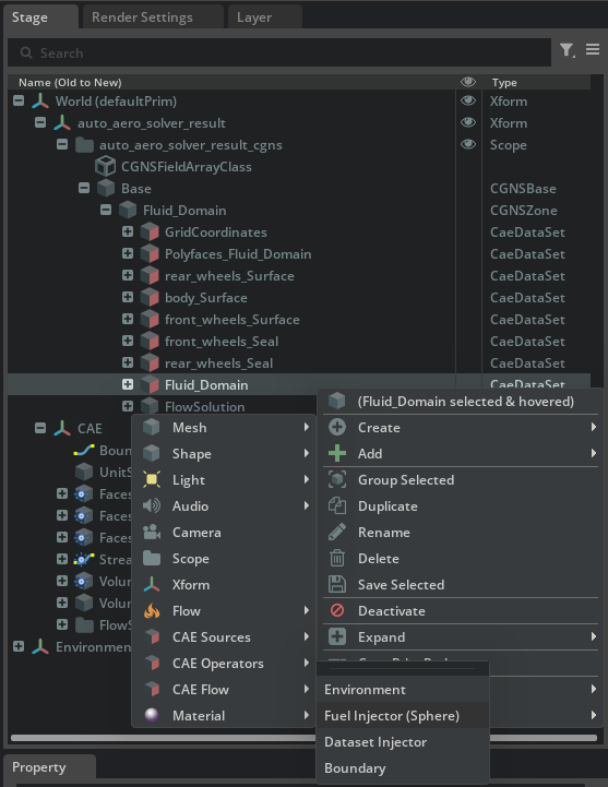
Right-click
Fluid_Domainagain and select Create > CAE Flow > DataSet Injector.
Select
/World/CAE/FlowSimulation_L0/DatasetInjector_Fluid_Domainin the Stage panel. In the Property panel, scroll to the Dataset [Voxelization] section and set Inflate Bounds (%) to 100. This expands the voxelization region to prevent flow particles from escaping the area of interest.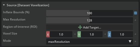
Still in the injector’s properties, scroll to Velocity and click Add Target. Shift-select
Velocity_0,Velocity_1, andVelocity_2fromFlowSolution.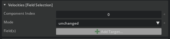
To start the flow animation, select the
FlowSimulateprim and check Force Simulate in the Property panel, or press Play on the timeline.
Tip
Select the fuel injector sphere and move it to a different position. The flow particles emit from the new location, letting you explore flow behavior interactively.