Articulations#
Articulations provide an alternative, and often superior approach to simulating mechanisms composed of jointed rigid bodies. Typically, you achieve higher simulation fidelity with articulations as they have zero joint error by design, and can handle larger mass ratios between the jointed bodies. PhysX simulates articulations in reduced-coordinates, where the configuration of the articulation is determined by its root body and the joint angles instead of the world pose of each body involved.
You can often turn jointed rigid bodies into an articulation given that they do not contain unsupported joints, see the Joint Table, and ensuring that loops are resolved appropriately. In order to enable articulation simulation on jointed rigid bodies, apply the UsdPhysics.ArticulationRootAPI component to the appropriate primitive, see USD Hierarchy / Articulation Root.
In the following, we often use the term (articulation) link for a rigid body that is part of an articulation.
Note
If you encounter stability issues with articulations in your robot simulations, please refer to the Articulation and Robot Simulation Stability Guide.
Articulation Tree Structure#
Articulations must have a tree structure in terms of the rigid-body links and the joints between them (loops are possible, however). The tree structure is created solely by the Body 0 and Body 1 relationships of the joints connecting the articulation links (i.e. rigid bodies) - the USD hierarchy has no impact on the articulation structure other than during parsing, see below. Therefore, you may organize the joints and links in the stage tree as you see fit.
Here are two example articulations: A ragdoll and a robotic arm.
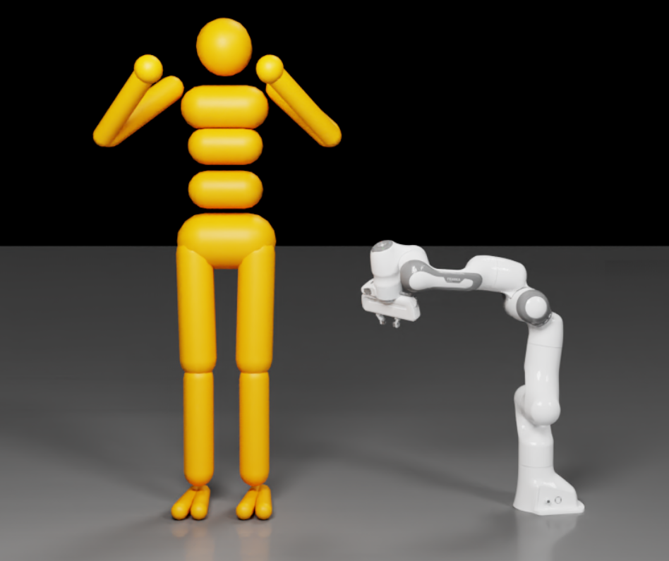
The tree structure for the arm is straightforward: The root is at the base on the ground plane, and revolute joints connect the different links up to the manipulator, where the tree has its only branch to connect the two gripper parts to the end-effector with prismatic (i.e. linear) joints.
For the ragdoll, we can choose any link, i.e. limb as the root and the resulting structure is always a tree. For example, we can choose the head to be the root, and connect the torso to it with a spherical joint, which in turn uses spherical joints to attach the arms, and so on.
While in practice, the root can be placed on any link for a floating-base articulation, it is a good rule of thumb to choose a central node such that traversal distances to the leaf nodes of the articulation are reduced. The heuristic for root-node determination described in Create an Articulation Based on Topology typically leads to the selection of central links. Of course, the application may require setting the root to a specific link, e.g. a quadruped torso, because control algorithms are designed around this topology.
Note
An implication of the articulation algorithm operating on reduced coordinates is that contrary to non-articulation jointed rigid bodies, setting poses and velocities on non-root links is not supported and triggers a warning in the console. For further differences and limitations, please see Articulation Limitations and Differences.
Floating and Fixed-Base#
There is a key difference between the two articulation examples: The ragdoll is a floating articulation which means the root (e.g. the head) and therefore the entire robot may move freely in space.
The robot arm is a fixed-base articulation: Its base, i.e. root link is fixed to the world frame.
USD Hierarchy / Articulation Root#
You should consider the USD hierarchy when you apply the UsdPhysics.ArticulationRootAPI component to a prim such that one or more articulations are created.
The rules are as follows:
For a fixed-base articulation, add the Root API either to:
the fixed joint that connects the articulation base to the world, or
an ancestor of the fixed joint in the USD hierarchy. See more information in Create an Articulation Based on Topology.
In the robotic-arm example above, we connect the robot’s base to the world frame using a fixed joint, and then could, for example, apply the root component to this joint.
Note that there is no need to specify the joint frames of the fixed joint since its joint frames are ignored; the main purpose of the fixed joint is to specify the root link. Further note that any joint type supported by articulations may be used as a joint for the root link to the world frame. However, it is recommended that you use a fixed joint, because it best expresses the intention.
For a floating-base articulation, add the Articulation Root component either to:
the rigid-body link that shall be the root, or
an ancestor of the root link in the USD hierarchy. See more information in Create an Articulation Based on Topology.
In the ragdoll example, we could, for example, apply the root component to the head link.
Create a Floating-Base Articulation#
The following Python snippet creates a single dynamic rigid body and converts it to an articulation link that is the root link of a floating-base articulation. The script also sets initial pose and velocity of the root link, which is only possible on root links if articulations are used.
The snippet may be extended to add further links and joints using the USD schema introduced in sections Rigid Bodies, Colliders, and Joints.
from pxr import Usd, UsdGeom, UsdPhysics, Gf, PhysxSchema
import omni.usd

# Create a stage
omni.usd.get_context().new_stage()
stage  = omni.usd.get_context().get_stage()

# Define the root Xform (transformable object)
rootxform = UsdGeom.Xform.Define(stage, "/World")

rigidBodyPath = "/World/rigidBody"

# Initial pose and velocity
rigidBodyStartPosition = Gf.Vec3f(0, 0, 0)
rigidBodyStartRotation = Gf.Quatf(1.0)
rigidBodyStartLinVelocity = Gf.Vec3f(0, 10, 0)
rigidBodyStartAngVelocity = Gf.Vec3f(0, 0, 10)

# Create the rigid body
rigidBodyXform = UsdGeom.Xform.Define(stage, rigidBodyPath)
rigidBodyXform.AddTranslateOp().Set(rigidBodyStartPosition)
rigidBodyXform.AddOrientOp().Set(rigidBodyStartRotation)
rigidBodyPrim = rigidBodyXform.GetPrim()

# Apply the rigid body api and set the body's initial state.
rigidBodyAPI = UsdPhysics.RigidBodyAPI.Apply(rigidBodyPrim)
rigidBodyAPI.CreateRigidBodyEnabledAttr(True)
rigidBodyAPI.CreateVelocityAttr(rigidBodyStartLinVelocity)
rigidBodyAPI.CreateAngularVelocityAttr(rigidBodyStartAngVelocity)

# Auto-compute the mass properties of the rigid body
massAPI = UsdPhysics.MassAPI.Apply(rigidBodyPrim)
massAPI.CreateMassAttr(2.0)

# Apply the articulation api to the rigid body.
# rigidBodyPrim is now the root link of a floating
# articulation that has a single link.
UsdPhysics.ArticulationRootAPI.Apply(rigidBodyPrim)
Create a Fixed-Base Articulation#
The following snippet creates a fixed-base articulation with two links coupled by a revolute joint.
from pxr import Usd, UsdGeom, UsdPhysics, Gf, PhysxSchema
import omni.usd

# Create a stage
omni.usd.get_context().new_stage()
stage  = omni.usd.get_context().get_stage()

# Define the root Xform (transformable object)
rootxform = UsdGeom.Xform.Define(stage, "/World")

rigidBodyPaths = ["/World/rigidBody0", "/World/rigidBody1"]
revoluteJointPath = "/World/revoluteJoint"
fixedJointPath = "/World/fixedJoint"

# The initial pose of the root link.
rootLinkStartPosition = Gf.Vec3f(0, 0, 0)
rootLinkStartRotation = Gf.Quatf(1.0)
# The joint frames of the revolute joint coupling
# the two links of the articulation.
revoluteJointlocalPositions = [Gf.Vec3f(0.0, 10.0, 0.0), Gf.Vec3f(0.0, 0.0, 0.0)]
revoluteJointLocalRotations = [Gf.Quatf(1.0), Gf.Quatf(1.0)]

# body0 is chosen to be the root link.
rootLinkId = 0
rigidBodyXforms = [None] * 2

for i in range(2):

    # Create the rigid body
    rigidBodyXform = UsdGeom.Xform.Define(stage, rigidBodyPaths[i])
    rigidBodyXforms[i] = rigidBodyXform
    rigidBodyPrim = rigidBodyXform.GetPrim()
    rigidBodyAPI = UsdPhysics.RigidBodyAPI.Apply(rigidBodyPrim)
    rigidBodyAPI.CreateRigidBodyEnabledAttr(True)
    massAPI = UsdPhysics.MassAPI.Apply(rigidBodyPrim)
    massAPI.CreateMassAttr(2.0)


# Create a revolute joint between the two rigid body prims
revoluteJoint = UsdPhysics.RevoluteJoint.Define(stage, revoluteJointPath)
revoluteJoint.CreateAxisAttr(UsdPhysics.Tokens.y)
revoluteJoint.CreateBody0Rel().AddTarget(rigidBodyPaths[0])
revoluteJoint.CreateBody1Rel().AddTarget(rigidBodyPaths[1])
revoluteJoint.CreateLocalPos0Attr().Set(revoluteJointlocalPositions[0])
revoluteJoint.CreateLocalRot0Attr().Set(revoluteJointLocalRotations[0])
revoluteJoint.CreateLocalPos1Attr().Set(revoluteJointlocalPositions[1])
revoluteJoint.CreateLocalRot1Attr().Set(revoluteJointLocalRotations[1])

# Create a fixed joint between the root link and the world.
# Mark the fixed joint as the root. This will create a fixed
# base articulation with body0 as the root link.
fixedJoint = UsdPhysics.FixedJoint.Define(stage, fixedJointPath)
fixedJoint.CreateBody0Rel().AddTarget(rigidBodyPaths[rootLinkId])
UsdPhysics.ArticulationRootAPI.Apply(fixedJoint.GetPrim())

# Set the initial pose of the root link
rigidBodyXforms[rootLinkId].AddTranslateOp().Set(rootLinkStartPosition)
rigidBodyXforms[rootLinkId].AddOrientOp().Set(rootLinkStartRotation)
Create an Articulation Based on Topology#
When the articulation root is not directly applied to a fixed joint or rigid body, the simulator attempts to determine the articulation type and topology automatically.
- The automation process works as follows:
Traverse the hierarchy below the articulation root.
Create topologies, which are graphs based on the traversed bodies and joints connecting them.
For each topology, apply a deterministic algorithm to select the articulation root:
If any joint to the world is found, the topology (articulation) is considered fixed-base. The articulation root link is the body connected to the world with this joint.
If no world joint is found, the topology is considered floating-base. In this case, the articulation root is set to the graph node (articulation link) with minimal eccentricity.
Note that with this automation, it’s not possible to know the articulation root beforehand. As a result applying poses and velocities to the articulation root is not feasible unless the root is identified after parsing.
JointStateAPI for Set and Get of Joint Position And Velocity#
Each degree of freedom of an articulated joint has position and velocity attributes. These attributes may be queried or modified by applying PhysxSchema.JointStateAPI to the corresponding joint prim. This is a feature unique to articulated joints.
The PhysxSchema.JointStateAPI can be used to set initial position and velocity of the articulation joint. In the absence of the API, the simulation initializes the joint positions and velocities to zero.
The following Python snippet may be added to the snippet in section Create a Fixed-Base Articulation to set the initial position and velocity of the revolute joint:
jointStateAPI = PhysxSchema.JointStateAPI.Apply(revoluteJoint.GetPrim(), UsdPhysics.Tokens.angular)
jointStateAPI.CreatePositionAttr(45.0)
jointStateAPI.CreateVelocityAttr(180.0)
The position and velocity of the degree of freedom permitted by the revolute joint may be queried as follows:
jointPosition = jointStateAPI.GetPositionAttr().Get()
jointVelocity = jointStateAPI.GetVelocityAttr().Get()
Tokens such as UsdPhysics.Tokens.linear and UsdPhysics.Tokens.rotX are used to specify the degree of freedom whose state will be queried or modified.
For example, a prismatic joint would use the token UsdPhysics.Tokens.linear, while a spherical joint would use UsdPhysics.Tokens.rotX, UsdPhysics.Tokens.rotY, or UsdPhysics.Tokens.rotZ, as appropriate.
Note
For performance in reinforcement learning or other simulation workloads, you may enable the physics Fabric extension (see enabling Fabric). The above USD access to the joint state will no longer work in that case, but you can use the Tensor API ArticulationView instead that directly accesses PhysX data.
Articulation Joint Drive and Performance Envelope#
A drive, operating analogous to a PD controller, may be added to a joint. This is defined on a per-axis basis.
It is possible to define drive’s performance envelope, which acts as a static model that constrains the behavior of an articulated joint. This can be achieved by applying a multiple-apply PhysxDrivePerformanceEnvelopeAPI per joint axis. The following snippet demonstrates how to apply and configure this API on a revolute joint:
from omni.physx.bindings._physx import (
    PERF_ENV_API,
    PERF_ENV_ATTR_MAX_ACTUATOR_VELOCITY_ANGULAR,
    PERF_ENV_ATTR_VELOCITY_DEPENDENT_RESISTANCE_ANGULAR,
    PERF_ENV_ATTR_SPEED_EFFORT_GRADIENT_ANGULAR,
)

# Assume we have a revolute joint already created
# Apply drive API for the angular axis
driveAPI = UsdPhysics.DriveAPI.Apply(jointPrim, UsdPhysics.Tokens.angular)
driveAPI.CreateMaxForceAttr().Set(100.0)

# Apply performance envelope API for the angular axis
jointPrim.ApplyAPI(PERF_ENV_API, UsdPhysics.Tokens.angular)
jointPrim.CreateAttribute(PERF_ENV_ATTR_MAX_ACTUATOR_VELOCITY_ANGULAR, Sdf.ValueTypeNames.Float).Set(180.0)
jointPrim.CreateAttribute(PERF_ENV_ATTR_VELOCITY_DEPENDENT_RESISTANCE_ANGULAR, Sdf.ValueTypeNames.Float).Set(0.5)
jointPrim.CreateAttribute(PERF_ENV_ATTR_SPEED_EFFORT_GRADIENT_ANGULAR, Sdf.ValueTypeNames.Float).Set(2.0)
PhysX enforces operation within the envelope using:
Effort constraint:
\[|driveEffort| \leq maxEffort - velocityDependentResistance \cdot |jointVelocity|\]
Velocity constraint:
\[|jointVelocity| \leq maxActuatorVelocity - speedEffortGradient \cdot |driveEffort|\]
Where:
maxEffortcorresponds to the maximum force for linear joints or maximum torque for rotational joints and is configured using the maxForce attribute of the DriveAPI.velocityDependentResistancerepresents resistance that scales with velocity.speedEffortGradientrepresents how actuator speed capability decreases with applied effort.maxActuatorVelocityis the maximum achievable velocity for actuated joints.
These constraints define a feasible operating region in the (joint velocity, drive effort) plane.
Units (from PhysxDrivePerformanceEnvelopeAPI schema):
Linear joints:
maxForce: force [N]velocityDependentResistance: force × second / distancespeedEffortGradient: distance / second / forcemaxActuatorVelocity: distance / second
Angular joints:
maxForce: torque [Nm]velocityDependentResistance: torque × second / degreesspeedEffortGradient: degrees / second / torquemaxActuatorVelocity: degrees / second
The accompanying document Drive Performance Envelope describes deriving the performance envelope parameters from a typical motor datasheet.
Note
driveEffortrepresents the sum of:Internal drive effort (from PD controller)
User-defined joint effort
For the PhysxDrivePerformanceEnvelopeAPI to take effect, the PhysicsDriveAPI must also be defined for the same axis, as the maxForce parameter from PhysicsDriveAPI is utilized by the performance envelope.
Legacy behavior is achieved by not applying the PhysxDrivePerformanceEnvelopeAPI.
Differentiate between PhysxDrivePerformanceEnvelopeAPI:
maxActuatorVelocityand PhysxJointAxisAPI(PhysxJointAPI):maxJointVelocity. While the former is used for clamping the drive effort, the latter is used for clamping the joint velocity itself.
Articulation Joint Friction#
Joint friction is applied to an articulation joint when non-zero friction parameters are specified.
The updated friction model combines Coulomb friction (static and dynamic) with viscous friction. The behavior is as follows:
For each joint degree of freedom, the system evaluates whether the joint can be brought to rest using static friction alone. This is determined by comparing the impulse required to stop the joint (based on its current velocity) to the static friction impulse, which is computed from the
staticFrictionEffortparameter.If the static friction impulse is sufficient, the joint is held at rest along that axis.
If not, dynamic friction is applied to slow the joint down. This dynamic friction consists of:
A constant term derived from the
dynamicFrictionEffortparameter.A velocity-dependent term, calculated as the product of
viscousFrictionCoefficientand the joint velocity.
Users can customize this friction behavior per axis using PhysxJointAxisAPI. In addition, this API allows for setting the maximum joint velocity and armature per axis. The following snippet demonstrates how to apply and configure this API on a revolute joint:
from omni.physx.bindings._physx import (
    JOINT_AXIS_API,
    JOINT_AXIS_ATTR_STATIC_FRICTION_EFFORT_ANGULAR,
    JOINT_AXIS_ATTR_DYNAMIC_FRICTION_EFFORT_ANGULAR,
    JOINT_AXIS_ATTR_VISCOUS_FRICTION_COEFFICIENT_ANGULAR,
    JOINT_AXIS_ATTR_ARMATURE_ANGULAR,
    JOINT_AXIS_ATTR_MAX_JOINT_VELOCITY_ANGULAR,
)

# Assume we have a revolute joint already created
# Apply joint axis API for the angular axis
jointPrim.ApplyAPI(JOINT_AXIS_API, UsdPhysics.Tokens.angular)

jointPrim.CreateAttribute(JOINT_AXIS_ATTR_STATIC_FRICTION_EFFORT_ANGULAR, Sdf.ValueTypeNames.Float).Set(5.0)
jointPrim.CreateAttribute(JOINT_AXIS_ATTR_DYNAMIC_FRICTION_EFFORT_ANGULAR, Sdf.ValueTypeNames.Float).Set(3.0)
jointPrim.CreateAttribute(JOINT_AXIS_ATTR_VISCOUS_FRICTION_COEFFICIENT_ANGULAR, Sdf.ValueTypeNames.Float).Set(0.1)
jointPrim.CreateAttribute(JOINT_AXIS_ATTR_ARMATURE_ANGULAR, Sdf.ValueTypeNames.Float).Set(0.01)
jointPrim.CreateAttribute(JOINT_AXIS_ATTR_MAX_JOINT_VELOCITY_ANGULAR, Sdf.ValueTypeNames.Float).Set(10.0)
Note
staticFrictionEffort must always be greater than or equal to dynamicFrictionEffort.
Units (from PhysxJointAxisAPI schema):
Linear joints:
staticFrictionEffortanddynamicFrictionEffort: force (mass × distance / second²)viscousFrictionCoefficient: force × second / distancemaxJointVelocity: distance / secondarmature: mass
Angular joints:
staticFrictionEffortanddynamicFrictionEffort: torque (mass × distance² / second²)viscousFrictionCoefficient: torque × second / degreesmaxJointVelocity: degrees / secondarmature: mass × distance²
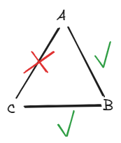
Closed Loops#
Articulation joints on their own do not support closed loops. For example, links A, B, C may be connected with articulation joints coupling A to B and B to C, but not with an articulation joint that also couples C to A. This final joint would create a closed loop of articulation joints and is not supported.
Closing loops is still possible by using a regular joint (rather than an articulation joint). This is achieved by marking the loop-closing joint as being excluded from the articulation. For the example above, this would involve marking the joint coupling C to A as excluded from the articulation, see below.
Note
Simulation of articulations with closed-loops is more challenging for the solver and you may encounter instabilities; try lowering the simulation time step, and follow other advice in Articulation and Robot Simulation Stability Guide.
Exclude Joints from Articulations#
You most often exclude joints from an articulation when breaking closed loops; but you may also use it to connect a swappable manipulator to a robot arm, i.e. to connect two articulations to each other using a fixed joint.
The snippet creates four links arranged at the corners of a square in the x-y plane. Each edge of the square has a corresponding joint which results in a closed loop. This loop is broken by excluding the last joint from the articulation. An additional joint is added to make the articulation fixed-base.
from pxr import Usd, UsdGeom, UsdPhysics, Gf, PhysxSchema
import omni.usd

# Create a stage
omni.usd.get_context().new_stage()
stage  = omni.usd.get_context().get_stage()

# Define the root Xform (transformable object)
rootxform = UsdGeom.Xform.Define(stage, "/World")

rootLinkfixedJointPath = "/World/rootLinkfixedJoint"
rigidBodyPaths = ["/World/rigidBody0", "/World/rigidBody1", "/World/rigidBody2", "/World/rigidBody3"]
rigidBodyBoxPaths = ["/World/rigidBody0/box", "/World/rigidBody1/box", "/World/rigidBody2/box", "/World/rigidBody3/box"]
rigidBodyStartPositions = [Gf.Vec3f(0, 0, 0), Gf.Vec3f(0, 10, 0), Gf.Vec3f(10, 10, 0), Gf.Vec3f(10, 0, 0)]
fixedJointPaths = ["/World/fixedJoint0", "/World/fixedJoint1", "/World/fixedJoint2", "/World/fixedJoint3"]
fixedJointBodyPairs = [[0, 1], [1,2], [2,3], [3,0]]

# The joint frames of the revolute joint coupling
# the two links of the articulation.
fixedJointlocalPositions0 = [Gf.Vec3f(0.0, 10.0, 0.0), Gf.Vec3f(10.0, 0.0, 0.0), Gf.Vec3f(0.0, -10.0, 0.0), Gf.Vec3f(-10.0, 0.0, 0.0)]
fixedJointlocalPositions1 = [Gf.Vec3f(0.0, 0.0, 0.0), Gf.Vec3f(0.0, 0.0, 0.0), Gf.Vec3f(0.0, 0.0, 0.0), Gf.Vec3f(0.0, 0.0, 0.0)]
fixedJointLocalRotations0 = [Gf.Quatf(1.0), Gf.Quatf(1.0), Gf.Quatf(1.0), Gf.Quatf(1.0)]
fixedJointLocalRotations1 = [Gf.Quatf(1.0), Gf.Quatf(1.0), Gf.Quatf(1.0), Gf.Quatf(1.0)]

for i in range(4):

    # Create the rigid body
    rigidBodyXform = UsdGeom.Xform.Define(stage, rigidBodyPaths[i])
    rigidBodyXform.AddTranslateOp().Set(rigidBodyStartPositions[i])
    rigidBodyPrim = rigidBodyXform.GetPrim()
    rigidBodyAPI = UsdPhysics.RigidBodyAPI.Apply(rigidBodyPrim)
    rigidBodyAPI.CreateRigidBodyEnabledAttr(True)
    massAPI = UsdPhysics.MassAPI.Apply(rigidBodyPrim)
    massAPI.CreateMassAttr(2.0)

for i in range(4):

    fixedJoint = UsdPhysics.FixedJoint.Define(stage, fixedJointPaths[i])
    body0Index = fixedJointBodyPairs[i][0]
    body1Index = fixedJointBodyPairs[i][1]
    fixedJoint.CreateBody0Rel().AddTarget(rigidBodyPaths[body0Index])
    fixedJoint.CreateBody1Rel().AddTarget(rigidBodyPaths[body1Index])
    fixedJoint.CreateLocalPos0Attr().Set(fixedJointlocalPositions0[body0Index])
    fixedJoint.CreateLocalRot0Attr().Set(fixedJointLocalRotations0[body0Index])
    fixedJoint.CreateLocalPos1Attr().Set(fixedJointlocalPositions1[body1Index])
    fixedJoint.CreateLocalRot1Attr().Set(fixedJointLocalRotations1[body1Index])
    if i==3:
        fixedJoint.CreateExcludeFromArticulationAttr(True)

# Create a fixed joint to the world and define it
# as the articulation root
rootLinkFixedJoint = UsdPhysics.FixedJoint.Define(stage, rootLinkfixedJointPath)
rootLinkFixedJoint.CreateBody0Rel().AddTarget(rigidBodyPaths[0])
UsdPhysics.ArticulationRootAPI.Apply(rootLinkFixedJoint.GetPrim())
Articulation Mimic Joints#
Mimic joints allow the position of two degrees of freedom of the same articulation to be coupled with a linear relationship.
For example, you can use mimic joints to create
a gear joint by coupling two revolute joints, or
a rack-and-pinion-joint by coupling a prismatic and revolute joint.
Note that when simulating articulations, it is recommended that you use mimic joints instead of the Meta Joints implementations of the gear and rack-and-pinion joints. Mimic joints are articulation-specific and fully GPU accelerated.
Mimic joints are characterized by a gear ratio \(G\) and an offset \(\gamma\) such that:
with \(q_A\) and \(q_B\) denoting the positions of the two degrees of freedom coupled by the mimic joint.
Note
Mimic joints only support revolute joints with limits applied. The limits may have any value. For example, setting the limit to a very large value could create a situation where the limit is never exceeded.
Mimic joints only support articulation joints.
The following Python snippet creates a mimic joint that implements a gear-joint relationship. The mimic joint couples the two revolute joint positions of joint0 and joint1. Then, joint0 is initialized to an angular speed of 800 degrees per second, while joint1 is initialized to zero angular speed. The mimic joint with gear ratio five will then pull joint1 along as the simulation progresses.
from pxr import Usd, UsdGeom, UsdPhysics, Gf, PhysxSchema, Sdf
import omni.usd

# Create a stage
omni.usd.get_context().new_stage()
stage  = omni.usd.get_context().get_stage()

# Define the root Xform (transformable object)
rootxform = UsdGeom.Xform.Define(stage, "/World")

rootBodyPath = "/World/rootBody"
rootBodyFixedJointPath = "/World/rootBodyFixedJoint"

rigidBodyPaths = ["/World/rigidBody0", "/World/rigidBody1"]
rigidBodySpherePaths = ["/World/rigidBody/sphere", "/World/rigidBody/sphere"]
sphereRadii = [5, 5]
revoluteJointPaths = ["/World/revoluteJoint0", "/World/revoluteJoint1"]
revoluteJointBody0Positions = [Gf.Vec3f(-5, 0, 0), Gf.Vec3f(5, 0, 0)]

# Create the root body
rootBodyXform = UsdGeom.Xform.Define(stage, rootBodyPath)
rootBodyXform.AddTranslateOp().Set(Gf.Vec3f(0.0))
rootBodyXform.AddOrientOp().Set(Gf.Quatf(1.0))
rootBodyPrim = rootBodyXform.GetPrim()
rigidBodyAPI = UsdPhysics.RigidBodyAPI.Apply(rootBodyPrim)
rigidBodyAPI.CreateRigidBodyEnabledAttr(True)

# Create two siblings (body0 and body1) as children of the root.
# Create an inbound revolute joint (joint0 and joint1) for each child.
for i in range(2):

    # Create a rigid body
    rigidBodyXform = UsdGeom.Xform.Define(stage, rigidBodyPaths[i])
    rigidBodyPrim = rigidBodyXform.GetPrim()
    rigidBodyAPI = UsdPhysics.RigidBodyAPI.Apply(rigidBodyPrim)
    rigidBodyAPI.CreateRigidBodyEnabledAttr(True)
    massAPI = UsdPhysics.MassAPI.Apply(rigidBodyPrim)
    massAPI.CreateDensityAttr(2.0)

    # Add a sphere collider
    sphereGeom = UsdGeom.Sphere.Define(stage, rigidBodySpherePaths[i])
    sphereGeom.CreateRadiusAttr(sphereRadii[i])
    sphereGeom.AddTranslateOp().Set(Gf.Vec3f(0.0))
    sphereGeom.AddOrientOp().Set(Gf.Quatf(1.0))
    spherePrim = sphereGeom.GetPrim()
    UsdPhysics.CollisionAPI.Apply(spherePrim)

    # Create a revolute joint between the root link and the rigid body
    revoluteJoint = UsdPhysics.RevoluteJoint.Define(stage, revoluteJointPaths[i])
    revoluteJoint.CreateBody0Rel().AddTarget(rootBodyPath)
    revoluteJoint.CreateBody1Rel().AddTarget(rigidBodyPaths[i])
    revoluteJoint.CreateAxisAttr(UsdPhysics.Tokens.z)
    revoluteJoint.CreateLocalPos0Attr().Set(revoluteJointBodyPositions[i])
    revoluteJoint.CreateLowerLimitAttr(-9000.0)
    revoluteJoint.CreateUpperLimitAttr(9000.0)

# Create a fixed joint between the root body and the world.
# Mark the fixed joint as the root. This will create a fixed
# base articulation with body0 as the root link.
fixedJoint = UsdPhysics.FixedJoint.Define(stage, rootLinkFixedJointPath)
fixedJoint.CreateBody0Rel().AddTarget(rigidBodyPaths[0])
UsdPhysics.ArticulationRootAPI.Apply(fixedJoint.GetPrim())

jointPrim0 = stage.GetPrimAtPath(revoluteJointPaths[0])

# Apply a joint speed to one of the revolute joints
jointStateAPI = PhysxSchema.JointStateAPI.Apply(jointPrim0, UsdPhysics.Tokens.angular)
jointStateAPI.CreatePositionAttr(0.0)
jointStateAPI.CreateVelocityAttr(800.0)

# Create a mimic joint
mimicJointAPI = PhysxSchema.PhysxMimicJointAPI.Apply(jointPrim0, UsdPhysics.Tokens.rotZ)
mimicJointAPI.GetReferenceJointRel().AddTarget(revoluteJointPaths[1])
mimicJointAPI.GetReferenceJointAxisAttr().Set(UsdPhysics.Tokens.rotZ)
mimicJointAPI.GetGearingAttr().Set(5.0)
mimicJointAPI.GetOffsetAttr().Set(0.0)
Articulation Mimic Joint Compliance#
Mimic joints support compliance, as discussed here in the PhysX SDK guide. In the absence of compliance, mimic joints apply the impulses necessary to instantaneously maintain the mimic joint equation. This can lead to instability in the event that another sub-system is pushing back equally hard to break the mimic joint constraint.
Gripping scenarios may exhibit mimic joint instability when finger joints are “passively” actuated via a mimic joint connected to a driven joint. This scenario is especially prone to instability when the driven joint is configured to be very stiff (i.e. high position gain) compared to the typically small masses and inertia of finger links: When the finger tip is in contact with an object, the mimic joint will be a constraint competing with the hard contact which may cause stability issues.
One solution to the numerical issues arising from the competing constraints is to add compliance to the mimic joints. Mimic joint compliance is achieved with two parameters that model compliance as a spring-damper: natural frequency and damping ratio.
The following python script may be added to the script in section Articulation Mimic Joints to add compliance to a mimic joint:
# Set the compliance attributes of the mimic joint
mimicJointAPI.GetNaturalFrequencyAttr().Set(100.0)
mimicJointAPI.GetDampingRatioAttr().Set(1.2)
Tuning a Compliant Mimic Joint#
A metric that helps tuning compliance is the product of simulation timestep and natural frequency. Larger product values are more likely to lead to instability, while smaller product values are more likely to lead to stability. If the product of simulation timestep and natural frequency is many orders of magnitude greater than 1, there is no effective compliance, and you may just as well avoid configuring compliance.
A good starting point for the product of natural frequency and simulation timestep is 1. This might lead to the mimic joint appearing sluggish. Increase the natural frequency until the sluggishness is reduced to an acceptable or even imperceptible level but not so great that the compliance has no effect.
Increasing the number of position iterations with the TGS solver reduces the effective simulation timestep. This is particularly true when the behavior of the articulation is not dominated by collision response.
Joints such as gear and rack-and-pinion joints are rarely underdamped. Avoid damping ratios less than 1 to avoid oscillations arising from underdamping. Avoid values much greater than 1 to avoid sluggish approaches to the equilibrium state of the mimic joint.
Note that increasing the number of position iterations and/or reducing the simulation timestep incurs a performance penalty. For recovering some performance, see also the hints in Reduce Simulation Timestep for Complex Systems and Closed Loops.
Articulation Tendons#
Tendons create constraints within articulations. There are two types: Fixed and Spatial
Fixed tendons impose constraints on joint positions, while spatial tendons impose constraints on the lengths between selected links.
Fixed Tendons#
Fixed tendons couple degrees of freedom of an articulation such that the weighted sum of the coupled joint positions (the tendon length) is driven towards a specified rest length. In the event that the tendon length is outside a permitted range, the tendon length may also be driven back towards the permitted range.
The articulation joints referenced by a fixed tendon must follow the topology of the articulation. Another way of expressing this is that the sequence of articulation joints referenced by a tendon must follow the sequence of joints of the articulation. The sequence may start and end at any joint, provided each adjacent pair in the sequence share a common link.
Each articulation joint referenced by a fixed tendon has an associated gear ratio used to compute the tendon length. Moreover, each articulation joint has an associated force coefficient, which is used to scale the force applied to each joint. The force coefficients are chosen heuristically to best help the fixed tendon achieve its goal. It is recommended to set the force coefficient associated with each joint in the fixed tendon to be the reciprocal of the associated gear ratio.
The rate at which a fixed tendon achieves its target length may be increased by increasing the stiffness or limit stiffness of the fixed tendon, as appropriate. The stiffness value controls the rate at which the fixed tendon approaches the specified rest length, while the limit stiffness controls the rate at which the tendon length approaches the upper or lower bound of the permitted range from outside the permitted range. Choices of stiffness and limit stiffness allow fixed tendons to observe only limits, to observe only the rest length or to observe both.
To avoid oscillations around the target length, fixed tendons support damping. Higher damping values will lead to the tendon length asymptotically approaching the target length, while lower damping values can lead to the tendon oscillating around the target length. The damping value is used to compute a damping force that is the product of the damping value and the tendon speed, with the damping speed of the tendon computed as the weighted sum of individual joint speeds. The force coefficients are again used to compute a damping force to apply to each individual joint of the fixed tendon.
The tendon length may be amended by adding a constant offset value to the weighted sum of joint positions. This offset can be used to control or actuate joints of the articulation through the fixed tendon.
The Fixed Tendon demo found in Physics Demo Scenes provides an example of a fixed tendon. The motion of the fixed tendon is shown in the following video.
The three articulation links shown in the video are connected by two revolute joints with the red link denoting the root link of the fixed base articulation. The outbound revolute joint of the root link is driven alternately to zero and forty-five degrees. The second revolute joint connecting the two blue links does not have a drive, but is constrained to follow the position of the driven joint by virtue of the fixed tendon and its gearing.
The following Python snippet creates a simple fixed tendon that couples two degrees of freedom such that the tendon length approaches a rest length. The tendon references just two joints and enforces the rule that the sum of the two joint positions is zero:
    from pxr import Usd, UsdGeom, UsdPhysics, Gf, PhysxSchema
    import omni.usd

    # Create a stage
    omni.usd.get_context().new_stage()
    stage  = omni.usd.get_context().get_stage()

    # Define the root Xform (transformable object)
    rootxform = UsdGeom.Xform.Define(stage, "/World")

    # paths to bodies and joints
    rigidBodyPaths = ["/World/rigidBody0", "/World/rigidBody1",  "/World/rigidBody2"]
    revoluteJointPaths = ["/World/revoluteJoint01", "/World/revoluteJoint12"]
    fixedJointPath = "/World/fixedJoint"

    # The initial pose of the root link.
    rootLinkStartPosition = Gf.Vec3f(0, 0, 0)
    rootLinkStartRotation = Gf.Quatf(1.0)
    # The joint frames of the revolute joint coupling
    revoluteJointlocalPositions0 = [Gf.Vec3f(0.0, 0.0, 0.0), Gf.Vec3f(0.0, 0.0, 0.0)]
    revoluteJointLocalRotations0 = [Gf.Quatf(1.0), Gf.Quatf(1.0)]
    revoluteJointlocalPositions1 = [Gf.Vec3f(-4.0, 0.0, 0.0), Gf.Vec3f(-4.0, 0.0, 0.0)]
    revoluteJointLocalRotations1 = [Gf.Quatf(1.0), Gf.Quatf(1.0)]

    # body0 is chosen to be the root link.
    rootLinkId = 0

    # The configuration of the fixed tendon.
    # With joint positions p0,p1 and joint speeds v0,v1 we have:
    # tendonLength = gearRatios[0]*p0 + gearRatios[1]*p1 = p0 + p1
    # tendonSpeed = gearRatios[0]*v0 + gearRatios[1]*v1 = v0 + v1
    # tendonForce = (tendonLength-restLength)*stiffness - tendonSpeed*damping
    # Force applied to joint0 is tendonForce*forceCoefficients[0]
    # Force applied to joint1 is tendonForce*forceCoefficients[1]
    # For simplicity, limitStiffness is 0 allowing limits to be left at default values.
    stiffness = 10.0
    limitStiffness = 0.0
    damping = 1.0
    restLength = 0.0
    offset = 0.0
    gearRatios = [1.0, 1.0]
    forceCoefficients = [1.0, 1.0]

    # The three links of the articulation.
    rigidBodyXforms = [None] * 3
    for i in range(3):

            # Create the rigid body prim
            rigidBodyXform = UsdGeom.Xform.Define(stage, rigidBodyPaths[i])
            rigidBodyXforms[i] = rigidBodyXform
            rigidBodyPrim = rigidBodyXform.GetPrim()
            rigidBodyAPI = UsdPhysics.RigidBodyAPI.Apply(rigidBodyPrim)
            rigidBodyAPI.CreateRigidBodyEnabledAttr(True)
            massAPI = UsdPhysics.MassAPI.Apply(rigidBodyPrim)
            massAPI.CreateMassAttr(2.0)


    # Create a revolute joint between body prim0 and body prim 1
    # Create a revolute joint between body prim 1 and body prim 2
    revoluteJoints = [None] * 2
    for i in range(2):
            revoluteJoint = UsdPhysics.RevoluteJoint.Define(stage, revoluteJointPaths[i])
            revoluteJoint.CreateAxisAttr(UsdPhysics.Tokens.y)
            revoluteJoint.CreateBody0Rel().AddTarget(rigidBodyPaths[i])
            revoluteJoint.CreateBody1Rel().AddTarget(rigidBodyPaths[i+1])
            revoluteJoint.CreateLocalPos0Attr().Set(revoluteJointlocalPositions0[i])
            revoluteJoint.CreateLocalRot0Attr().Set(revoluteJointLocalRotations0[i])
            revoluteJoint.CreateLocalPos1Attr().Set(revoluteJointlocalPositions1[i])
            revoluteJoint.CreateLocalRot1Attr().Set(revoluteJointLocalRotations1[i])
            revoluteJoints[i] = revoluteJoint

    # Create a fixed joint between the root link and the world.
    # Mark the fixed joint as the root. This will create a fixed
    # base articulation with body0 as the root link.
    fixedJoint = UsdPhysics.FixedJoint.Define(stage, fixedJointPath)
    fixedJoint.CreateBody0Rel().AddTarget(rigidBodyPaths[rootLinkId])
    UsdPhysics.ArticulationRootAPI.Apply(fixedJoint.GetPrim())

    # Set the initial pose of the root link
    rigidBodyXforms[rootLinkId].AddTranslateOp().Set(rootLinkStartPosition)
    rigidBodyXforms[rootLinkId].AddOrientOp().Set(rootLinkStartRotation)

# Create a fixed tendon root and configure its properties.
fixedTendonRootApi = PhysxSchema.PhysxTendonAxisRootAPI.Apply(revoluteJoints[0].GetPrim(), "FixedTendon")
fixedTendonRootApi.CreateStiffnessAttr().Set(stiffness)
fixedTendonRootApi.CreateDampingAttr().Set(damping)
fixedTendonRootApi.CreateLimitStiffnessAttr().Set(limitStiffness)
fixedTendonRootApi.CreateRestLengthAttr().Set(restLength)
fixedTendonRootApi.CreateOffsetAttr().Set(offset)
PhysxSchema.PhysxTendonAxisAPI(revoluteJoints[0].GetPrim(), "FixedTendon").CreateGearingAttr().Set([gearRatios[0]])
PhysxSchema.PhysxTendonAxisAPI(revoluteJoints[0].GetPrim(), "FixedTendon").CreateForceCoefficientAttr().Set([forceCoefficients[0]])

# Add the 2nd joint of the articulation to the fixed tendon and configure its properties.
fixedTendonAxisApi = PhysxSchema.PhysxTendonAxisAPI.Apply(revoluteJoints[1].GetPrim(), "FixedTendon")
fixedTendonAxisApi.CreateGearingAttr().Set([gearRatios[1]])
fixedTendonAxisApi.CreateForceCoefficientAttr().Set([forceCoefficients[1]])
Spatial Tendons#
Spatial tendons create line-of-sight constraints between links of a single articulation. This allows, for example, modeling hydraulic actuators that can push and pull on links; artificial muscles in a biomimetic robot; or elastic-string-like mechanical components.
Each link of an articulation may have any number of associated tendon attachments with each having a specified offset from the relevant link. Spatial tendons are created as chains of attachments such that the total length of the tendon is the weighted sum of the distances between each pair of attachments as they are encountered along the topological chain. The tendon length may be amended by adding a constant offset value to the weighted sum of distances between attachments. This offset can be used for control and actuation of articulation links through the tendon.
The tendon length is driven towards a rest length with stiffness and damping values. In the event that the tendon length is outside a permitted range, the tendon length may also be driven back towards the permitted range with a limitStiffness value.
The rate at which a spatial tendon achieves its target length may be increased by increasing the stiffness or limit stiffness of the spatial tendon, as appropriate. The stiffness value controls the rate at which the spatial tendon approaches the specified rest length, while the limit stiffness controls the rate at which the tendon length approaches the upper or lower bound of the permitted range from outside the permitted range. Choices of stiffness and limit stiffness allow spatial tendons to observe only limits, to observe only the rest length or to observe both.
To avoid oscillations around the target length, spatial tendons support damping. Higher damping values will lead to the tendon length asymptotically approaching the target length, while lower damping values can lead to the tendon oscillating around the target length. The damping value is used to compute a damping force that is the product of the damping value and the tendon speed, with the tendon speed computed as the rate of change of the distance between the attachment pairs nearest the root and leaf of the chain.
The root and leaf attachments of a tendon are identified using PhysxTendonAttachmentRootAPI and PhysxTendonAttachmentLeafAPI. The attachments in-between are identified using PhysxTendonAttachmentAPI. By definition, PhysxTendonAttachmentRootAPI has no parent attachment, while both PhysxTendonAttachmentLeafAPI and PhysxTendonAttachmentAPI are required to have parent attachments.
Each type of attachment has an associated instance name and link. PhysxTendonAttachmentLeafAPI and PhysxTendonAttachmentAPI additionally have an associated parent attachment instance name and a path to the link of the parent attachment. If a link has multiple attachments, each of those attachments must have a different instance name to allow each of those multiple attachments to be uniquely identified. No other rules govern the naming convention of attachments.
The Spatial Tendon Actuation demo found in Physics Demo Scenes provides an example of a spatial tendon. The motion of the spatial tendon is shown in the following video.
The moving links of the two articulations are held up against gravity and actuated by tendons. The spheres are the debug visualization of the attachments that define the tendon geometry, and the blue lines visualize the line-of-sight distances that the tendons constrain using spring-damper forces.
The three different attachment-sphere colors distinguish the different types of attachments:
Root attachments (cyan) provide tendon-wide parameters such as spring-damper parameters, etc. The root attachments experience the reaction forces of the constraint forces applied to the leaf attachments.
Regular attachments (magenta) are used to route a tendon along articulation links. There is no force propagation through regular attachments, so they do not exert any forces on the links.
Leaf attachments (yellow) exert constraint forces to enforce a distance constraint on the path from the leaf to the root. A spatial tendon may branch, and, therefore, each leaf defines a sub-tendon with its own distance constraint. The leaf has sub-tendon specific parameters, such as the sub-tendon rest length and limits.
As previously stated, the tendon length of a (sub-)tendon is the sum of line-of-sight distances between the attachments on the path from a leaf to the root attachment. In this case, the tendon length is the length traversed when travelling from the cyan attachment to the magenta attachment to the yellow attachment.
The direction of the forces that are applied to roots and leaves is defined by the tendon geometry. For example, in the video above, the yellow leaf attachments apply a force to the moving links in the direction of the blue line towards the magenta middle attachment; analogously, the equal-magnitude root reaction force is also in the direction of the magenta middle attachment.
In the demo, the two tendons demonstrate two separate approaches to actuation: The front tendon moves the middle attachment while keeping the target tendon length constant, while the rear tendon changes the target tendon length. Further details such as sizing of the spring-damper parameters are presented in detail in the demo Python code. Full details on the tendon dynamics are available in the USD schema documentation of PhysxTendonAttachmentRootAPI.
The following Python snippet creates a spatial tendon with 3 links, 2 joints and 4 attachments. The attachments are configured to create a tendon with a rest length of 6 distance units and a start length of 9 distance units:
from pxr import Usd, UsdGeom, UsdPhysics, Gf, PhysxSchema
import omni.usd

# Create a stage
omni.usd.get_context().new_stage()
stage  = omni.usd.get_context().get_stage()

# Define the root Xform (transformable object)
rootxform = UsdGeom.Xform.Define(stage, "/World")

# paths to bodies and joints
rigidBodyPaths = ["/World/rigidBody0", "/World/rigidBody1",  "/World/rigidBody2"]
prismaticJointPaths = ["/World/prismaticJoint01", "/World/prismaticJoint12"]

# path to fixed joint that will help create a fixed base articulation
fixedJointPath = "/World/fixedJoint"

# The initial pose of the root link.
rootLinkStartPosition = Gf.Vec3f(0, 0, 0)
rootLinkStartRotation = Gf.Quatf(1.0)

# The start positions of prismaticJoint01 and prismaticJoint12
# These start positions give an initial tendon length of 9.0
prismaticJointStartPositions = [4.0, 5.0]

# The configuration of the spatial tendon.
stiffness = 10.0
limitStiffness = 0.0
damping = 1.0
restLength = 6.0
offset = 0.0

# body0 is chosen to be the root link.
rootLinkId = 0

# The three links of the articulation.
rigidBodyXforms = [None] * 3
for i in range(3):

    # Create a rigid body prim
    rigidBodyXform = UsdGeom.Xform.Define(stage, rigidBodyPaths[i])
    rigidBodyXforms[i] = rigidBodyXform
    rigidBodyPrim = rigidBodyXform.GetPrim()
    rigidBodyAPI = UsdPhysics.RigidBodyAPI.Apply(rigidBodyPrim)
    rigidBodyAPI.CreateRigidBodyEnabledAttr(True)
    massAPI = UsdPhysics.MassAPI.Apply(rigidBodyPrim)
    massAPI.CreateMassAttr(2.0)


# Create a prismatic joint between body prim0 and body prim 1
# Create a prismatic joint between body prim 1 and body prim 2
prismaticJoints = [None] * 2
for i in range(2):
    prismaticJoint = UsdPhysics.PrismaticJoint.Define(stage, prismaticJointPaths[i])
    prismaticJoint.CreateAxisAttr(UsdPhysics.Tokens.x)
    prismaticJoint.CreateBody0Rel().AddTarget(rigidBodyPaths[i])
    prismaticJoint.CreateBody1Rel().AddTarget(rigidBodyPaths[i+1])
    jointStateAPI = PhysxSchema.JointStateAPI.Apply(prismaticJoint.GetPrim(), UsdPhysics.Tokens.linear)
    jointStateAPI.CreatePositionAttr().Set(prismaticJointStartPositions[i])
    prismaticJoints[i] = prismaticJoint

# Create a fixed joint between the root link and the world.
# Mark the fixed joint as the root. This will create a fixed
# base articulation with body0 as the root link.
fixedJoint = UsdPhysics.FixedJoint.Define(stage, fixedJointPath)
fixedJoint.CreateBody0Rel().AddTarget(rigidBodyPaths[rootLinkId])
UsdPhysics.ArticulationRootAPI.Apply(fixedJoint.GetPrim())

# Set the initial pose of the root link
rigidBodyXforms[rootLinkId].AddTranslateOp().Set(rootLinkStartPosition)
rigidBodyXforms[rootLinkId].AddOrientOp().Set(rootLinkStartRotation)

# Create:
# a single attachment to rigidBodyXforms[0]
# two attachments to rigidBodyXforms[1]
# a single attachment to rigidBodyXforms[2]
# The attachment to rigidBodyXforms[0] will play the role of the tendon root
# The attachment to rigidBodyXforms[2] will play the role of the tendon leaf
# The attachments to rigidBodyXforms[1] complete the chain in-between the root and the leaf.
# Attachments to the same link must have different instance names.
# Attachments to different links may have the same instance name.
# In this example, the root and leaf attachment are named "SpatialTendon"
# and the two attachments to rigidBodyXforms[1] are given instance names
# "Minus" and "Plus".

# Create a spatial tendon root attached to rigidBodyXforms[0] and with name "SpatialTendon"
attachment0API = PhysxSchema.PhysxTendonAttachmentRootAPI.Apply(rigidBodyXforms[0].GetPrim(), "SpatialTendon")
attachment0API.CreateStiffnessAttr().Set(stiffness)
attachment0API.CreateDampingAttr().Set(damping)
attachment0API.CreateOffsetAttr().Set(offset)
attachment0API.CreateLimitStiffnessAttr().Set(offset)
PhysxSchema.PhysxTendonAttachmentAPI(attachment0API , "attachment0").CreateLocalPosAttr().Set(Gf.Vec3f(0.0, 0.0, 0.0))

# Create the 1st attachment to rigidBodyXforms[1] with name "Minus"
# The attachment is positioned at (-1,0,0) in the frame of rigidBodyXforms[1]
# The parent of the attachment is attachment0API
attachment1API = PhysxSchema.PhysxTendonAttachmentAPI.Apply(rigidBodyXforms[1].GetPrim(), "Minus")
attachment1API.CreateParentLinkRel().AddTarget(rigidBodyXforms[0].GetPrim().GetPath())
attachment1API.CreateParentAttachmentAttr().Set("SpatialTendon")
attachment1API.CreateGearingAttr().Set(1.0)
attachment1API.CreateLocalPosAttr().Set(Gf.Vec3f(-1.0, 0.0, 0.0))

# Create the 2nd attachment to rigidBodyXforms[1] with name "Plus"
# The attachment is positioned at (1,0,0) in the frame of rigidBodyXforms[1]
# The parent of the attachment is attachment1API
attachment2API = PhysxSchema.PhysxTendonAttachmentAPI.Apply(rigidBodyXforms[1].GetPrim(), "Plus")
attachment2API.CreateParentLinkRel().AddTarget(rigidBodyXforms[1].GetPrim().GetPath())
attachment2API.CreateParentAttachmentAttr().Set("Minus")
attachment2API.CreateGearingAttr().Set(1.0)
attachment2API.CreateLocalPosAttr().Set(Gf.Vec3f(1.0, 0.0, 0.0))

# Create an attachment attached to rigidBodyXforms[2] and with name "SpatialTendon"
# The parent of the attachment is attachment2API
attachment3API = PhysxSchema.PhysxTendonAttachmentLeafAPI.Apply(rigidBodyXforms[2].GetPrim(), "SpatialTendon")
attachment3API.CreateRestLengthAttr().Set(restLength)
PhysxSchema.PhysxTendonAttachmentAPI(attachment3API, "SpatialTendon").CreateParentLinkRel().AddTarget(rigidBodyXforms[1].GetPrim().GetPath())
PhysxSchema.PhysxTendonAttachmentAPI(attachment3API, "SpatialTendon").CreateParentAttachmentAttr().Set("Plus")
PhysxSchema.PhysxTendonAttachmentAPI(attachment3API, "SpatialTendon").CreateGearingAttr().Set(1.0)
PhysxSchema.PhysxTendonAttachmentAPI(attachment3API, "SpatialTendon").CreateLocalPosAttr().Set(Gf.Vec3f(0.0, 0.0, 0.0))
Articulation Limitations and Differences#
The following list describes further differences and limitations:
Each articulation link has a single inbound joint and any loops in the topology must be broken as described in Articulation Joint Drive and Performance Envelope.
Articulations do not support all types of USD joints, see the list here for compatibility.
Articulation joints of type
UsdPhysics.SphericalJointhave swing limits that form a pyramid rather than an elliptical cone.Articulation joints only support a single linear degree of freedom or up to three angular degrees of freedom, you should consider this limitation when a D6 Joint is to be included in an articulation.
Initial articulation joint violations are resolved before the first simulation step involving the articulation. Joint violations arising from joint-position limits persist until the simulation resolves them. See also JointStateAPI for Set and Get of Joint Position And Velocity.
Articulation joints do not support the breaking force and torque attributes associated with
UsdPhysics.Joint.Articulation joints may not be removed from the stage at run-time (after a simulation step has been performed).
Articulation joints support querying and setting velocity and position attributes of each degree of freedom of a joint with the
PhysxSchema.JointStateAPI.Articulated joints with a single degree of angular motion may accumulate a joint position greater than 360° if limits are enabled on the joint. This is true of joints that are configured with
UsdPhysics.RevoluteJointand joints that are configured withUsdPhysics.Jointand allow only angular motion around a single axis. The joint position of a revolute joint that does not have limits applied will wrap on a 360° boundary.Articulated joints configured using
UsdPhysics.JointandUsdPhysics.LimitAPIdo not support distance limits configured with theUsdPhysics.Tokens.distancetoken.Articulation joints may not be instanced, see Joint Instancing.
The
breakForceattribute ofUsdPhysics.Jointis ignored for articulation joints.Articulation joint limits are hard constraints that do not support stiffness and damping parameters in the
PhysxSchema.PhysxLimitAPI.Articulation joints without limits cannot be configured with limits after attaching the stage. If limits are required only temporarily it is recommended to initially configure the joint with unreachable high and low limits and then later update the limits so that they affect the joint’s motion. This way, the joint is effectively unlimited until required to behave as a limited joint.
Extensions and Articulations#
When you use extensions that access the underlying PhysX articulation data (e.g. Omni Physics Tensors), it is beneficial to set up articulations such that their USD and PhysX topologies are identical - only then do you get a one-to-one relationship between USD and PhysX joint parameters such as limits and drive targets. The USD physics interface must provide identical behavior for articulation and regular joints, and it may therefore swap joint limits or negate joint drive targets when parsing from USD to the PhysX articulation; this is because USD joints do not have to follow the articulation topology, e.g., it may be that the body0 relationship does not point to the parent link in the PhysX articulation, but the USD joint limit is defined in the body0 to body1 joint frame order.