OmniPVD - PhysX Visual Debugger#
Omniverse PhysX Visual Debugger (OmniPVD) allows the recording of data of a PhysX simulation for later visual and quantitative inspection. For example, you can record a rigid body box falling onto a ground plane, then replay the recording and inspect the motion of the box frame-by-frame to spot simulation issues. Besides the body transforms, the recording contains further simulation data, such as the values of the linear and angular velocity of the box at each frame.
OmniPVD consist of a shared dynamic library and the Omni PhysX Visual Debugger extension. The shared dynamic library is used both by the PhysX SDK simulation engine for the recording and writing of OmniPVD binary files (OVD) and by the OmniPVD extension to read and parse OVD files.
The OmniPVD extension makes it possible to import or load a PhysX recording in OVD format, transforming it seamlessly into a cached USDA format. After the OVD file is imported you can time scrub and analyze it as a USD Stage, which is good for debugging, inspecting, and visualizing a recorded PhysX scene, but it stays a pure animation. The OmniPVD gizmos can then be applied to the imported OVD file, for the sake of different visualizations such as collision contacts, bounding box representations, velocities as well as seeing mass, and transform reference frames.
It has a dedicated timeline that is geared towards replaying simulation steps and inspecting them more precisely. Use the OVD timeline instead of the alternatives because it allows for inspection of pre- and post-simulation frames.
Loading the OmniPVD Extension#
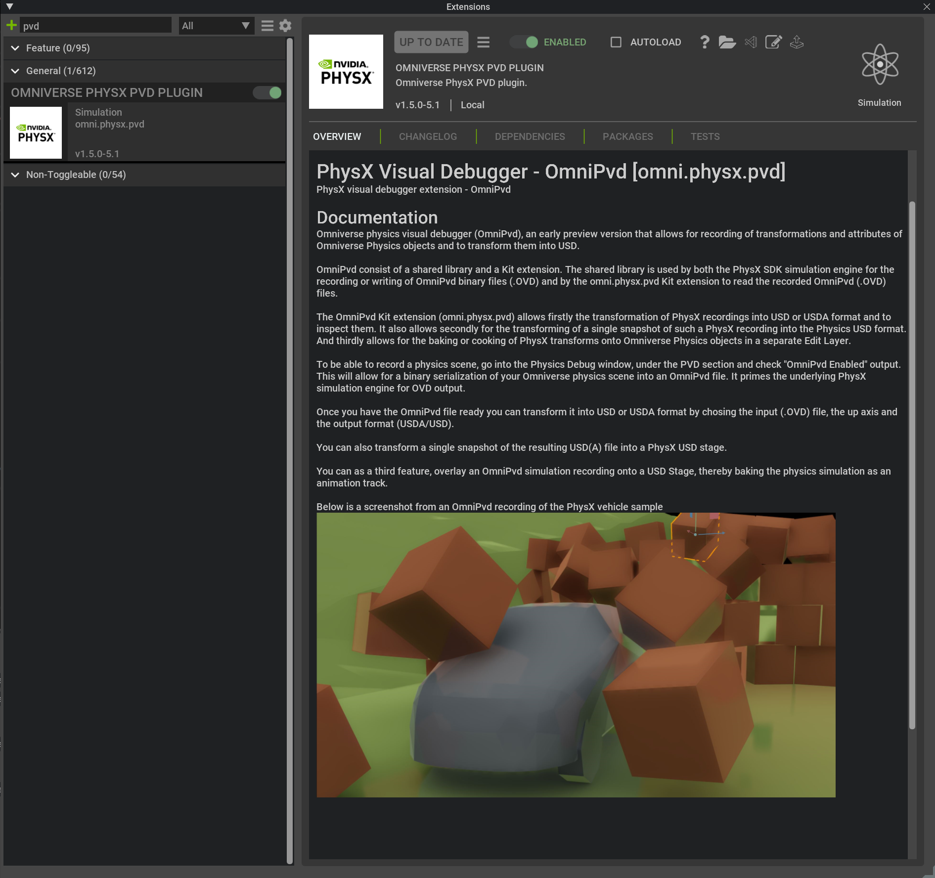
The Omni PhysX Visual Debugger extension can be found in the extension browser by searching for “pvd”. Make sure to click on the slider ENABLED, to move it into its rightmost position shown as green, to have it be activated and visible.
Recording a PhysX Simulation from the OmniPhysics Debug Window#
To record a PhysX scene in the OVD format:
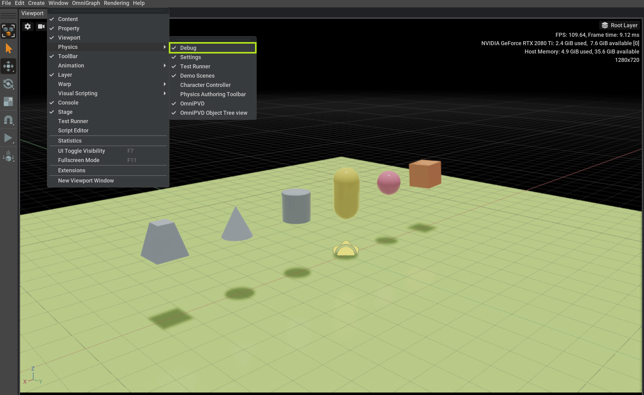
Make sure that the OmniPhysics Debug window is enabled and visible or that the OmniPVD extension window is visible, as will be discussed below. This can be done by going into the menu Window > Physics > Debug window and making sure it is marked checked.
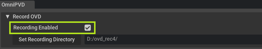
Then in the Physics Debug window in the OmniPVD section, check Recording Enabled.

Just underneath is a button called Set Recording Directory, which allows you to navigate to the desired OVD recording directory where time stamped OVD recordings will be saved.

By opening the directory of choice and by pressing Select Current, the OVD output directory is updated and set. Each time the Physics simulation is started and stopped, a new OVD recording is saved and time stamped into this directory as an
.ovdrecording.If the checkbox Recording Enabled is checked and enabled (not grayed out), as soon as the Play button is pressed, PhysX is now recording OmniPVD time stamped files into the OVD recording directory.
If the USD Stage is an OmniPVD Stage (it has OmniPVD prims) the checkbox “Recording Enabled” is grayed out, as it’s not possible to record any simulation data from an OmniPVD Prim, because it remains an animation.

Recording a Physics Simulation from the OmniPVD Window#
As was shown above you can record a physics scene from the Physics Debug window, but it’s also possible to do it from the OmniPVD extension:
Select “Recording Enabled. For example:
Select the recording directory using Set Recording Directory.

Enabling OmniPVD Recordings from the Command Line for a Headless Session#
If you need to record a PhysX simulation into OVD from a headless session:
You can enable OmniPVD recording from the command line using the following settings:
/persistent/physics/omniPvdOvdRecordingDirectory
/physics/omniPvdOutputEnabled
An example console command line, from Linux and not complete because the Stage is not defined:
bash kit/omni.app.dev.sh --no-window --/windowless=True --/persistent/physics/omniPvdOvdRecordingDirectory=/tmp/ --/physics/omniPvdOutputEnabled=true
- The order of the settings is important:
Set the output directory.
Enable the OVD output. If this order is not followed, the OVD recording will try to be written into a predefined directory, which might not exist. The writing operation will not crash but it will produce an error.
It is not required to load the OmniPVD extension to do recordings, but make sure to have the Omni PhysX extension loaded and do the recording from there. The OmniPVD extension is only necessary to import the produced OVD file.
Enabling OmniPVD Recordings from the Command Line for a Headless RL Session in IsaacLab#
IsaacLab users can record into OVD files with a special command line argument : –kit_args
./isaaclab.sh -p scripts/demos/bipeds.py --kit_args "--/persistent/physics/omniPvdOvdRecordingDirectory=/tmp/ --/physics/omniPvdOutputEnabled=true" --headless
Enabling OmniPVD Recordings via Python#
You can enable recording in a Python script. This might look like:
settings_ = carb.settings.get_settings()
settings_.set("/persistent/physics/omniPvdOvdRecordingDirectory", "/tmp/pvdout2/")
settings_.set("/physics/omniPvdOutputEnabled", True)
The order that you apply the settings is important. The same order as the console command, above, applies. The recording directory must be set first and then you can enable the output. You do not have to import the OmniPVD extension in the script to do OVD recordings. However, you must make sure to have the Omni PhysX extension imported.
OVD Recording File Name Structure#
In the OmniPVD recording settings, the OVD file names will be based on a time stamp and end in a file type of ovd.
The timestamp in the file name ensures that newer recordings do not overwrite older recordings.
If a duplicated timestamp does occur, there is a safety mechanism to ensure file names stay unique.
Loading an OVD File from the OmniPVD Window#
After a PhysX simulation is recorded into a time stamped OVD file, you can import or load it.
The loading operation automatically looks for a cached version of a corresponding USD Stage (in the Cache directory) and loads that if it exists.
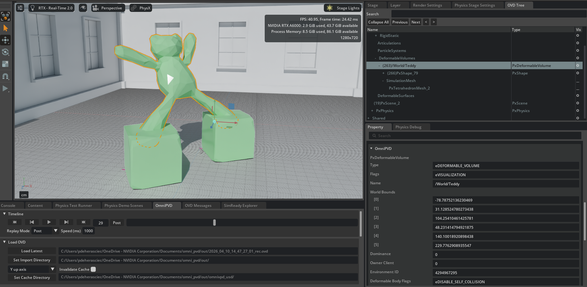
You can now explore the USD Stage of the imported OVD file, inspecting the recorded motion and data:
To import the latest OVD file in the import directory, press the Load Latest button in the file browser.
To load a specific file, see the next section on loading a file using the file import menu.
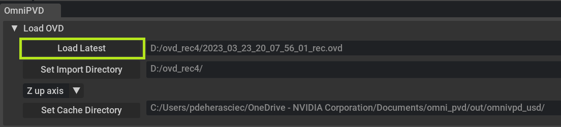
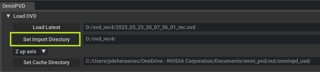
To change the directory from where to load the latest OVD file from, click Set Import Directory.
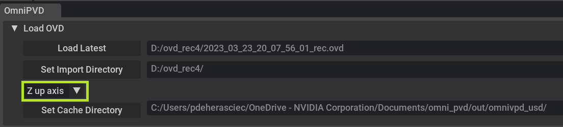
To override the up axis for the USD Stage that is automatically derived from the PhysX gravity vector, use the drop down menu for the Y or Z axis.
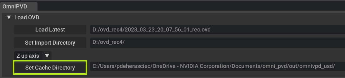
To set the cache directory where the USD Stages are stored, which are created on loading an OVD file, click Set Cache Directory. The next time the same OVD file is loaded, the USD Stage is directly loaded from there.
Loading an OVD File from the File Import Menu#
To load or import an OVD file from the menu:
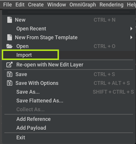
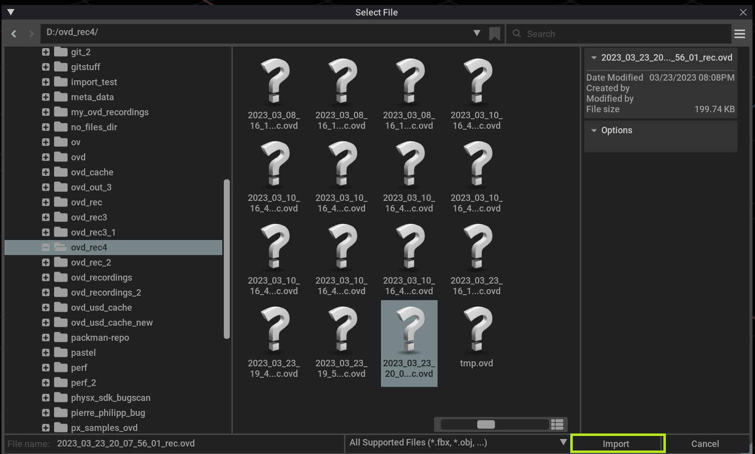
Navigate to File > Import, which opens up a file explorer dialog window.
Navigate to a specific file.
Double click or press the Import button in the explorer window to import the OVD file.
Automatic Stage Setup on OVD Import#
When an OVD file is imported, OmniPVD automatically configures the USD Stage for proper visualization:
Stage Lights: A distant light and a dome light are added to the Stage so that imported geometry is properly lit without manual setup. The distant light is positioned at a 315-degree rotation for good default illumination.
Meters Per Unit: The USD Stage metersPerUnit metadata is automatically set based on the PhysX tolerancesScale::length value recorded in the OVD file (metersPerUnit = 1 / tolerancesScale). This ensures that the scene scale matches the original simulation. The camera clipping range and global gizmo scale are also adjusted accordingly.
Recording Directory Creation: When setting the OVD recording output directory (via the /persistent/physics/omniPvdOvdRecordingDirectory setting), the directory hierarchy is automatically created if it does not exist. A trailing slash is also appended if missing to ensure the path is well-formed.
Dedicated Timeline#
The dedicated timeline, while similar to other USD animation timelines, works specifically on PhysX simulation steps in OVD files. The PhysX simulation steps can be divided into two frames, namely pre-simulation and post-simulation.
The pre-simulation frame covers PhysX user calls, such as adding a PxActor to a PxScene, various set operations, and collisions.
The post-simulation frame covers transforms, velocities, and any other parameters that were updated on PhysX objects.
Being able to inspect the simulation steps into two distinct and precise frames is valuable. For example in root cause analysis, knowing if user data was somehow out of bounds or ill defined can help you fix the issue.
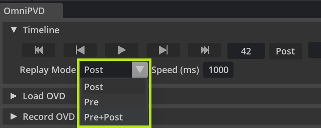
The timeline allows you to inspect the simulation in three modes, which are post-sim, pre-sim, and pre-sim + post-sim. The different modes allows you to inspect a specific type of frame or a mixed frame. They are listed in this order because post-sim is the default. Post-sim allows you to inspect all operations that happened up to and including the post-simulation step, therefore having the view of all operations that happened in a simulation step.
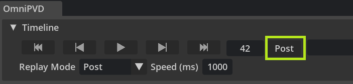
At any time you can determine the type of simulation frame you are in by inspecting the Pre or Post button. The button functions both as an indicator and as a switch from one mode to the other.
Note
Contact gizmos are only visualized for pre-sim frames. Make sure to be either in pre-sim or pre-sim + post-sim frame mode. You can also temporarily flip the frame mode to the Pre mode, by clicking on frame type button which shows as Pre or Post as below.
Independent of the simulation replay mode that you have selected, you can at any time use the Pre or Post button to switch back and forth between the frame types in a simulation step. For example, if you are in the pre-sim mode but momentarily want to inspect the post-simulation frame of the simulation step.
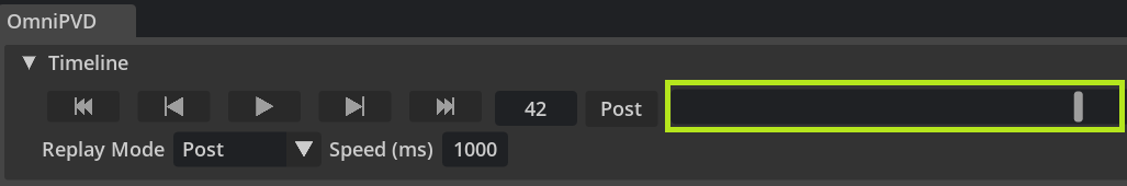
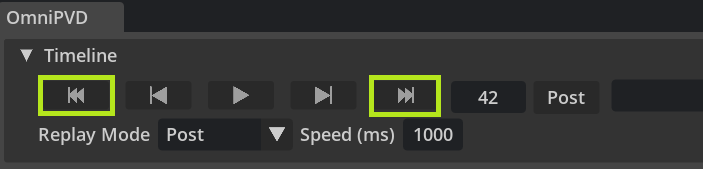
The timeline scrubber field allows you to drag the mouse to change the simulation step or frame. If the mode is pre or post, the scrubber moves in increments of a full simulation step. If it’s in pre+post mode, then the scrubbing can be adjusted to any pre- and post-simulation frame. The timeline scrubber field is highlighted below:
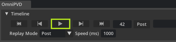
A timeline must also be able to playback an OVD recording. To playback the OVD recording there is the play button. The play button becomes a pause button as soon as the OVD recording is being played back. During play mode, the timeline shows each simulation frame. If the play mode is engaged, after the OVD recording reaches the end, pressing the play button again, moves the frame to the first one. See the play button placement below:
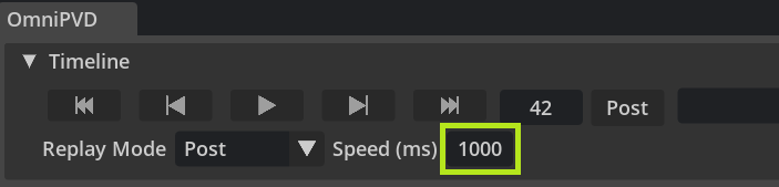
The wait time indicator/input button, is used to set the milliseconds to wait in between simulation steps or frames during the play mode. For example, if you input 50, then the timeline will wait 50 milliseconds before advancing to the next frame. It will not skip frames if the frame takes longer to load and display. The frame will take as long as it needs to load and display, then the timeline will wait the indicated amount of milliseconds, before proceeding to the next frame. No frames are skipped, however, if the mode is pre or post, only pre or post simulation frames will be played back.
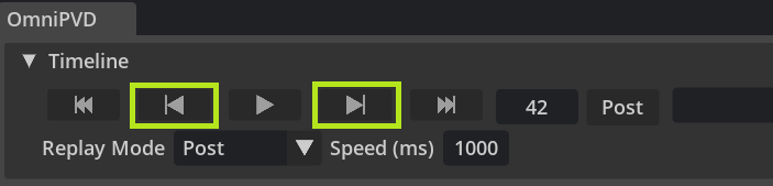
There is also the option to advance precisely one simulation step or frame (if the replay mode is pre+post), in the backwards direction or the forward direction by using the previous frame or next frame buttons. This is good for when you want to know exactly when a parameter changed. For example, inspecting a simulation frame by frame.
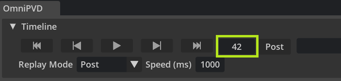
To indicate the simulation step you are in, as well as to give the option to jump to a specific frame, there is a step indicator/input button. You can input the step value with an integer (using the keyboard). The value also changes depending on the scrubbed value or if the play state is initiated.
It will not show an increase or decrease if you change the Pre/Post frame because the simulation step stays the same.
If you ARE interested in going to the start or the end of the OVD recording you can use the first or last buttons.
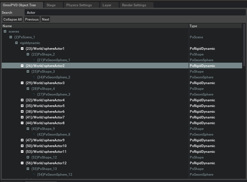
Object Tree and Property Widget#
The Object Tree features include:
Objects can have names derived from the OmniPVD object name (a string set at the object creation call), a PhysX actor name, or a combination of the OmniPVD class name and a unique identifier. The names do not have to be displayed with the USD Prim names (which have to follow strict SDF path rules).
Objects have the OmniPVD class displayed in the class column, not the USD Prim type.
The Object Tree search bar differs from the USD Stage search bar in the following ways:
The search bar expands the matching objects (based on their OVDTree name and UID) and allows for iterating through the results using the Prev/Next buttons. Results are not displayed in a flat list.
It’s possible to collapse the view and only display the root objects in the tree.
Every search result expands the existing expansion of the OVD Tree elements. For example, if you found something with a certain search string and then you found something else, both these searches (and any upcoming ones) are added to the expansions.
The Object Tree has three columns:
Name — displays the name with a UID prefix. Names can come from the OmniPVD object name, a PhysX actor name, or a combination of OmniPVD class name and unique identifier.
Visibility toggle (unlabeled column) — an eye icon toggle that controls whether a prim (and its descendants) is visible in the viewport. Clicking the eye icon sets the USD
purposeattribute toguide(hidden) ordefault(visible). Hidden prims stay hidden across frame changes, which is useful for isolating specific objects in complex scenes.Type — the OmniPVD class name (e.g.,
PxRigidDynamic,PxDeformableVolume), not the USD Prim type.
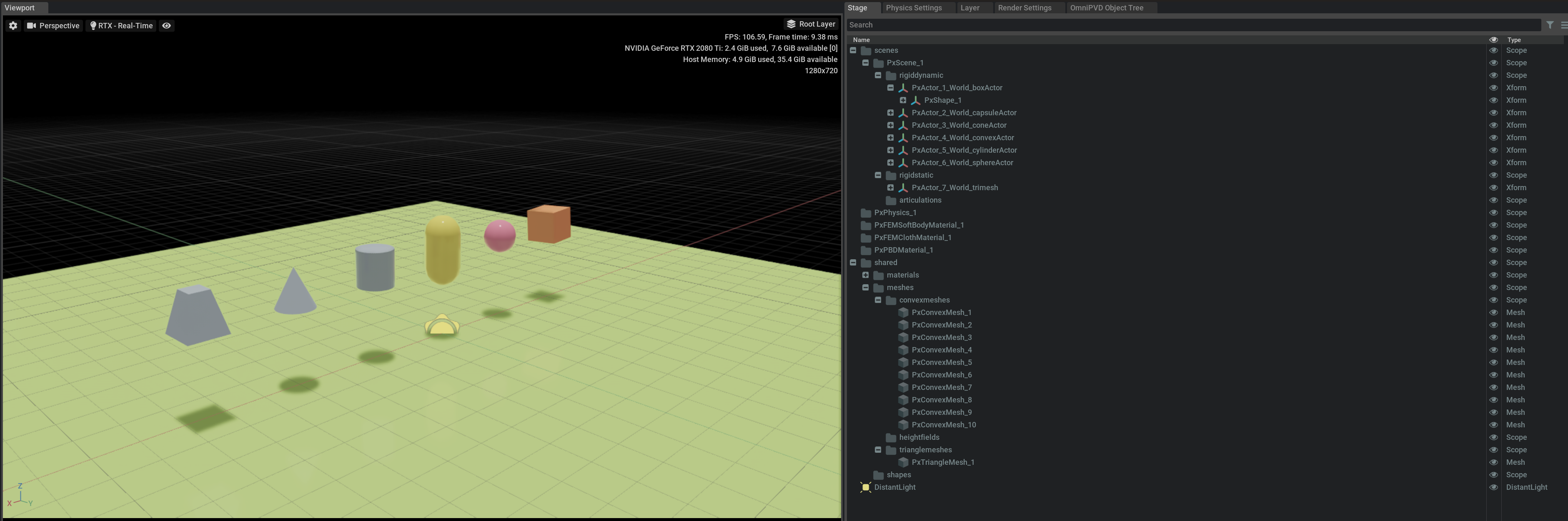
When an OVD file is imported, a cached Stage file is created. The USD hierarchy in the resulting file starts with a scene, then lists the different object classes that have populated each scene. These include dynamic rigid bodies, static rigid bodies, articulations, deformable volumes, deformable surfaces, particle systems, and their associated materials (routed to a shared Materials branch).
For deformable volumes, collision and simulation meshes are represented as separate selectable prims, allowing independent inspection of each mesh. Per-frame positions and velocities are stored on mesh objects for frame-by-frame analysis. Using the visibility toggle, individual meshes can be hidden to isolate the collision or simulation mesh in the viewport.
For each body, there is an actor or articulation link with accompanying shapes and geometries. Each USD Prim has a set of custom USD attributes, which can be explored in detail and if they change over time, can be scrubbed through the animation to see how they are updated.
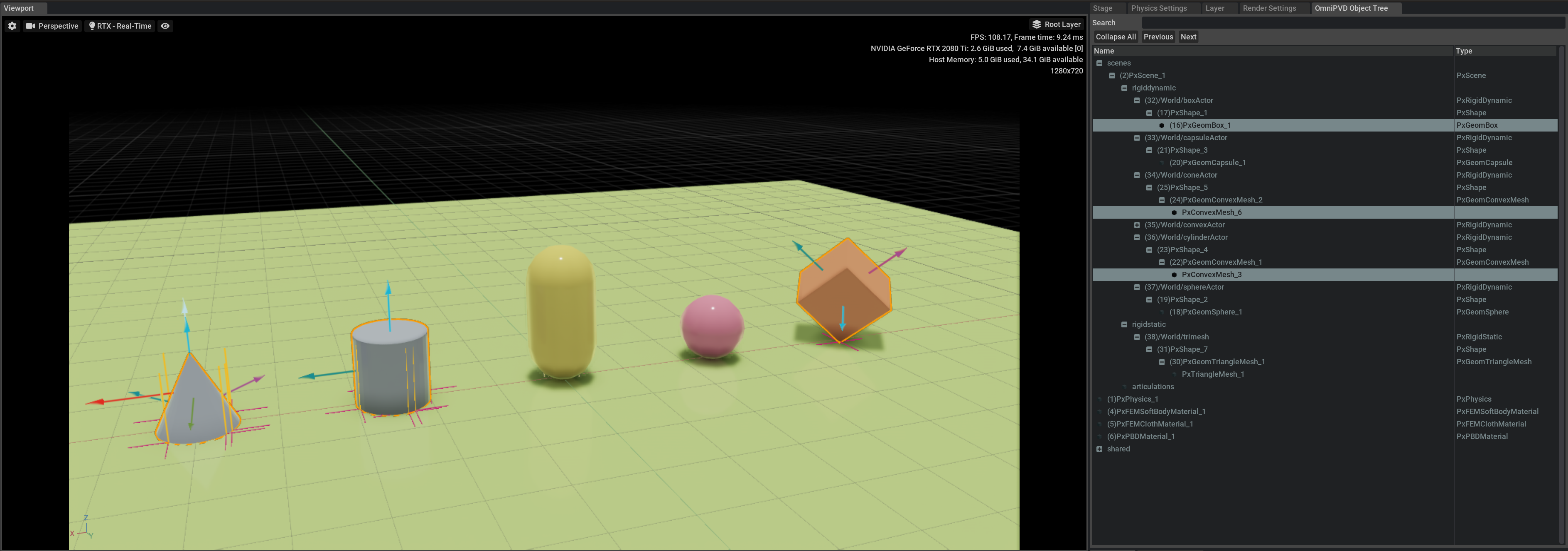
Another view of the Stage is in the OmniPVD Object Tree.
A Unique Identifier (UID) is prepended to all the objects, which is connected to the moment an object was created. It follows the creation/removal of objects, so only the objects that are active in the PhysX engine at that specific frame (defined by the timeline interface scrubber) are displayed in the tree. This is to have a more precise visualization of what was actually simulated in the frame.
Selection in the viewport selects the Prim geometries, but makes sure that the selection affects the owning PhysX classes that are above the geometries in the OVD Tree. This is to make sure that selection is a smooth and intuitive operation and does not break the existing interaction paradigm of the USD Stage.
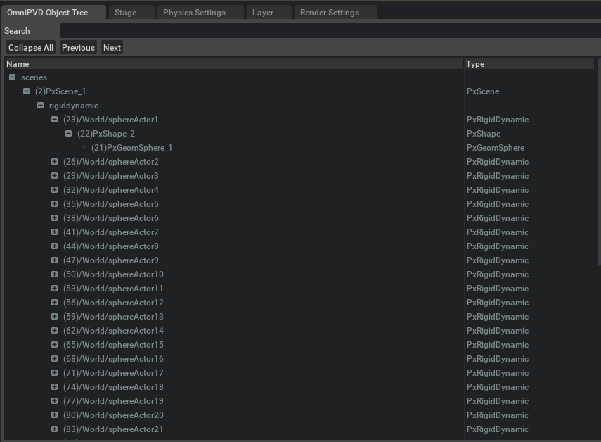
You can also search in the names of the OmniPVD objects or the UID and you get the resulting searches expanded and colored, with the possibility to walk through the results using the Next and Prev buttons. If you have done many searches, each search continues to expand the nodes, which can result in the expansion of all nodes. The Collapse All button collapses all expanded nodes of the tree.
Note
The search bar in the USD Stage only allows for search in the Prim path and Prim name.
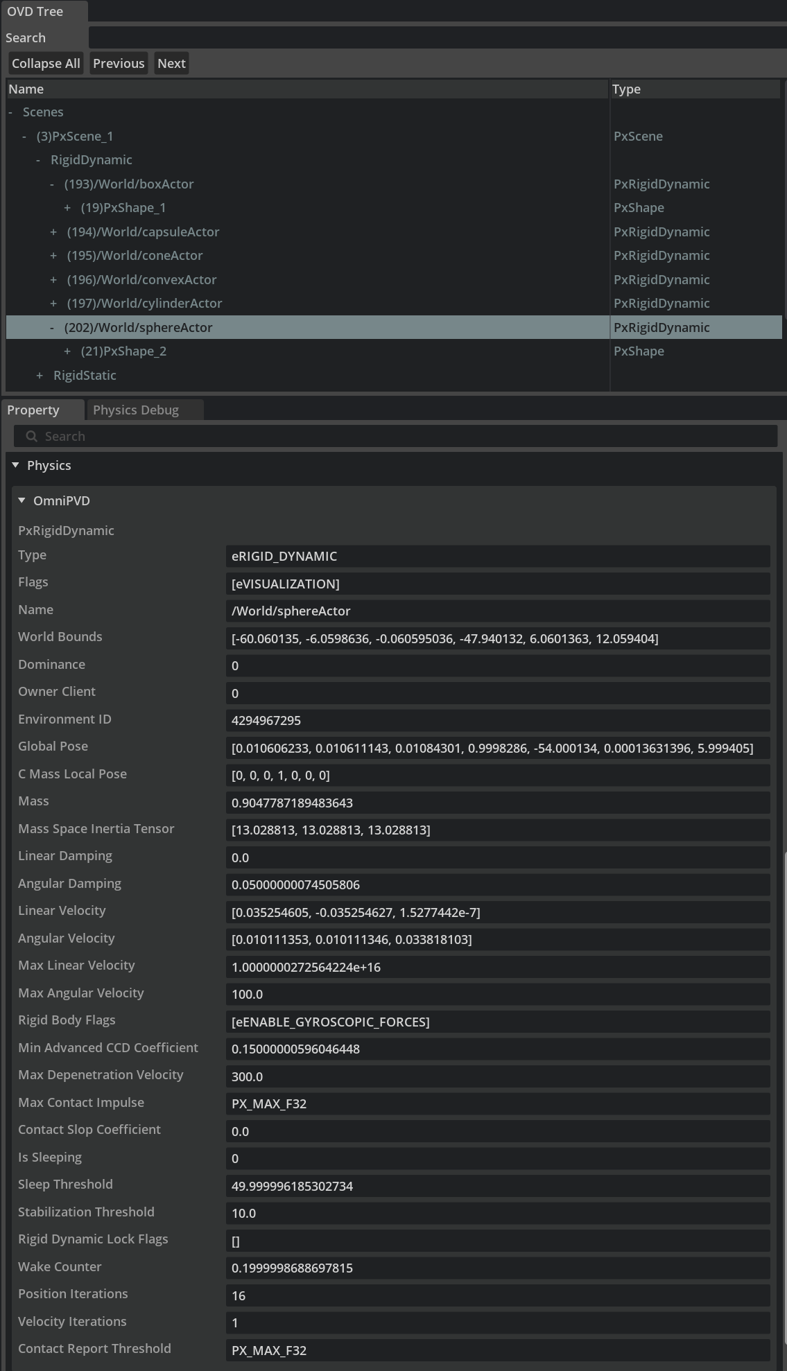
Below the Object Tree, is the Property window and inside the Physics widget lives the OmniPVD Property widget, which displays the OmniPVD attributes in a pretty printed form. The attributes in the widget get updated with the timeline changes in the USD Stage.
For attributes that contain arrays (such as unique list attributes), the Property widget provides paginated display with the following controls:
Previous page (
<) and Next page (>) buttons to navigate through pagesPageIndex — an editable field showing the current 0-based page index
PageSize — an editable field controlling how many elements are displayed per page (max 100)
NbrPages — read-only total page count
NbrElements — read-only total element count
The Property widget also provides reference navigation using < and > buttons (up to 50 entries in the history). Clicking a reference attribute navigates to the referenced prim and updates the Property widget. Scroll position is preserved when navigating between attributes on the same prim.
Object Hierarchies, Attributes and Units in OmniPVD are Based on PhysX#
In the above section on the Object Tree you can see how OmniPVD displays object hierarchies, attributes, names and units which are a reflection of the recorded underlying PhysX simulation stream.
There might be objects that are only present in the OVD recorded PhysX stream, that have no direct mapping to for example the OmniPhysics USD Schema classes and structures.
Object Color Coding#
OmniPVD assigns a primvars:displayColor to each object based on its type and simulation state. This color coding makes it easy to visually distinguish object types and their sleeping/awake state in the viewport:
Object Type |
Active |
Sleeping |
|---|---|---|
Rigid Static |
Light gray |
|
Rigid Dynamic |
Light pastel green |
Dark green |
Rigid Dynamic (Kinematic) |
Light pastel blue |
Dark blue |
Articulation |
Light pastel green |
|
Deformable Volume / Surface |
Light pastel green |
Dark green |
The color changes are animated over time — as objects fall asleep or wake up during the recording, their display color updates at the corresponding simulation frame.
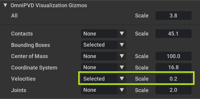
Visualization Gizmos#
The gizmos sub-window is located below the OmniPVD recording sub-window in the OmniPVD tab.
There are several ways to augment the imported OVD file with OmniPVD gizmos. Each gizmo type can be set to None, All, or Selected from the drop down menus below. Each type has an individual scale value, and a global All scale multiplier applies on top. The combined scale for any gizmo is the product of the global scale and its individual scale.
Selection is multi-directional between the viewport, the Stage, and the OmniPVD Object Tree. Selection can be done from the viewport, which also ends up selecting them in the Stage and OmniPVD Object Tree windows.
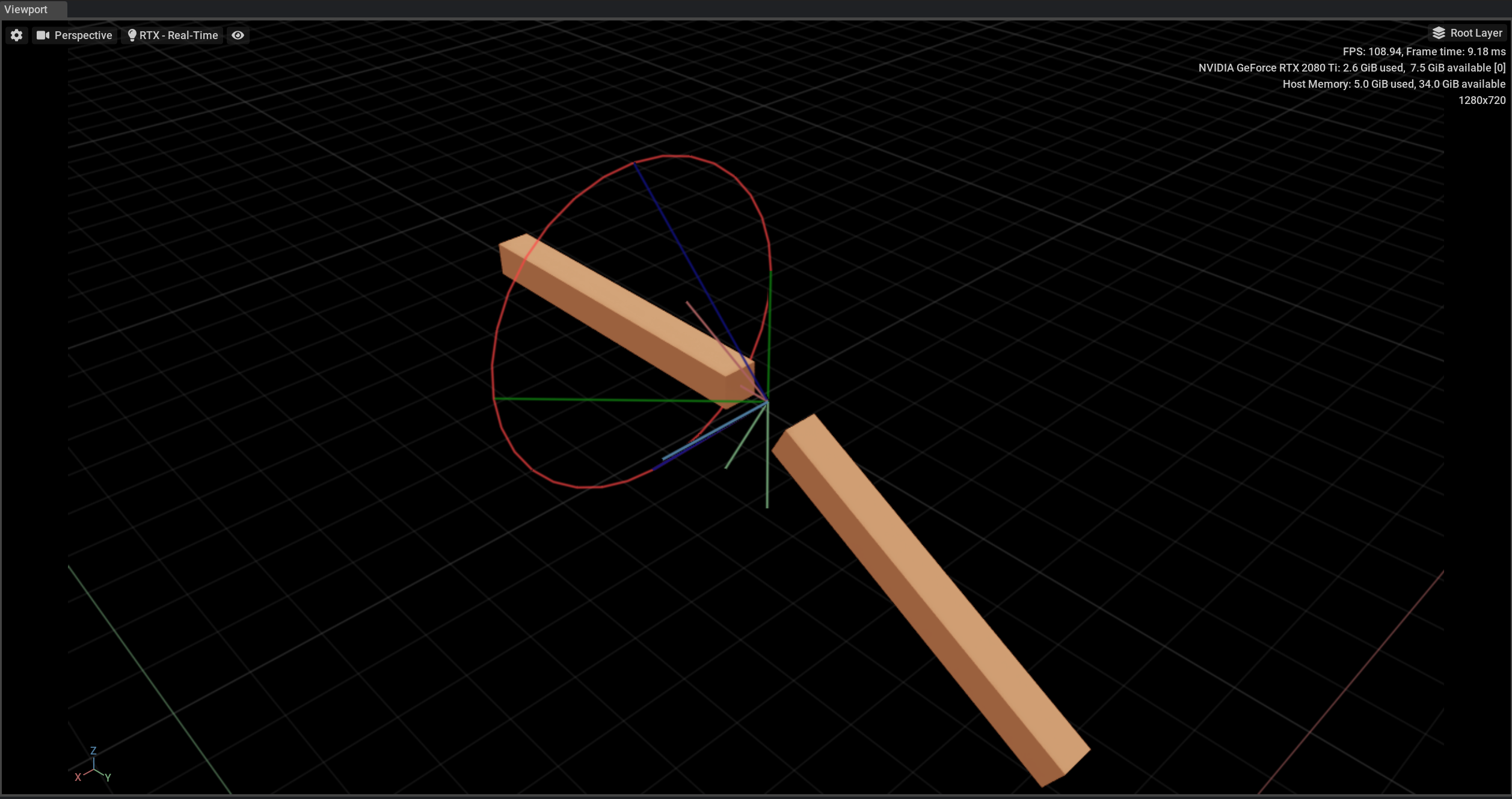
It’s for example possible to see bounding boxes, which are the same axis aligned bounding boxes, that PhysX uses internally to delineate the actors.
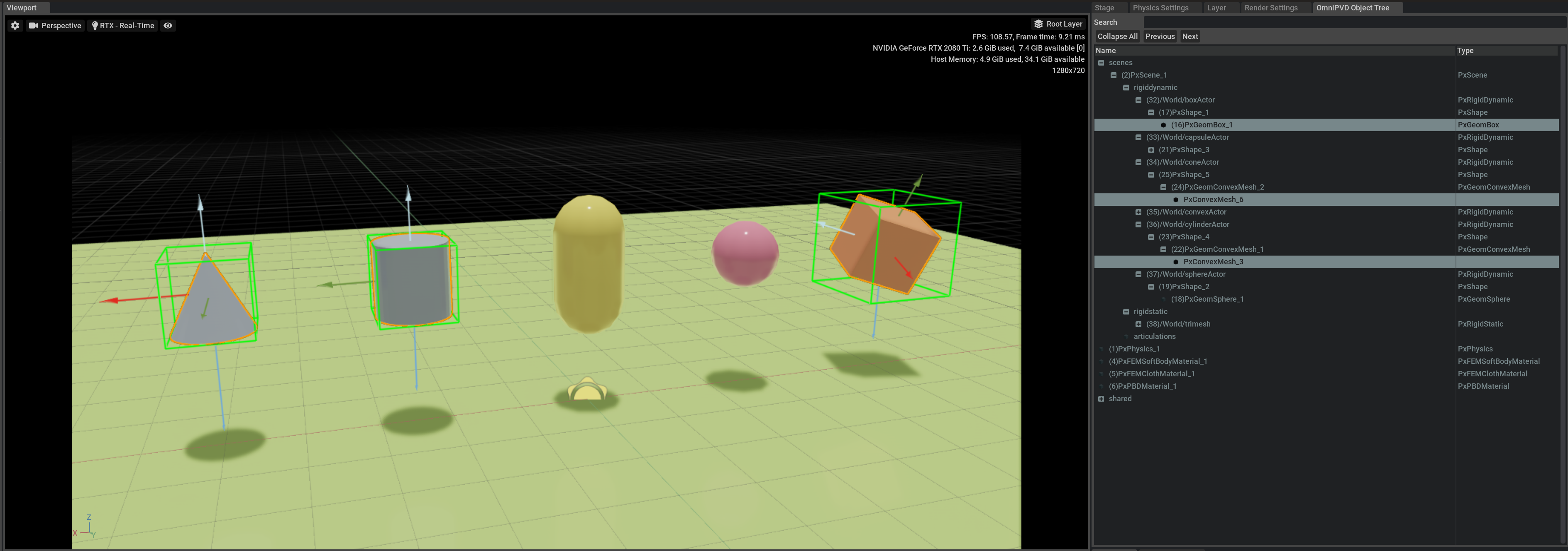
The contacts with the reference frame along with the mass reference frame are shown for the selected actors below.
Note
If the contacts don’t show up you might not be in the correct simulation frame mode, see Pre-Simulation Frame Type
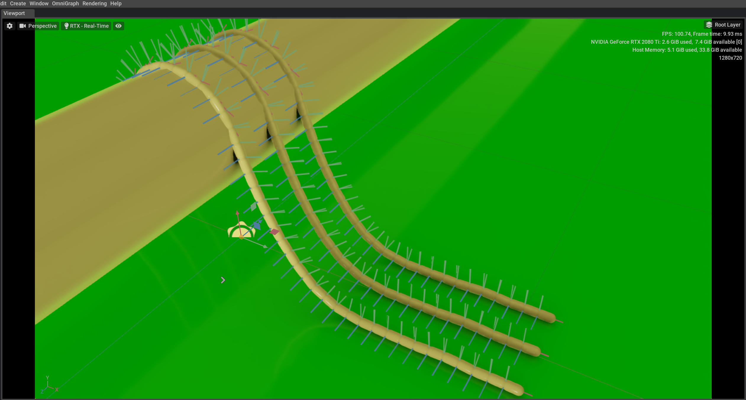
You can also view joints (such as D6, distance, gear, prismatic, rack and pinion). For example, this rope made out of D6 joints:
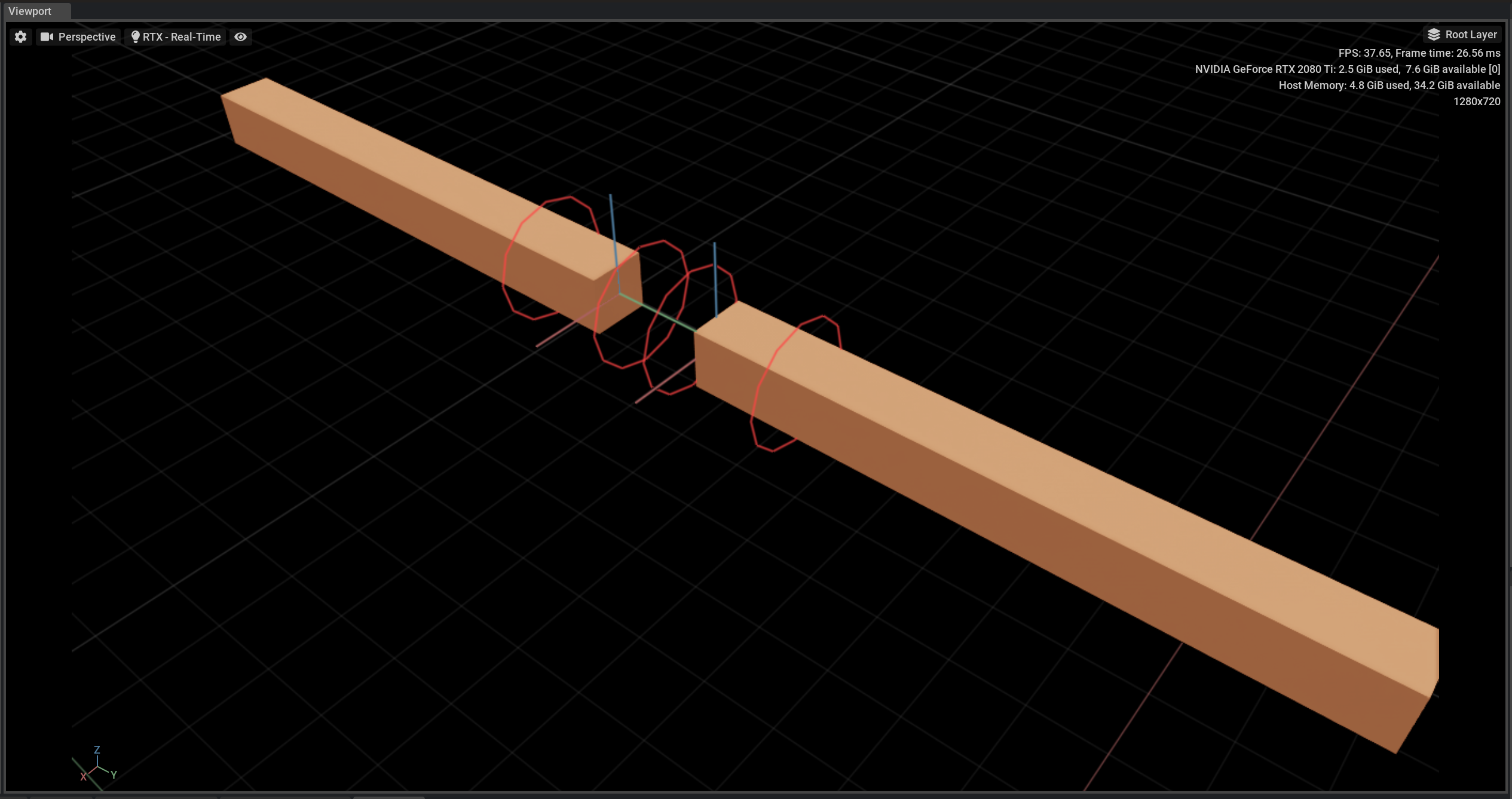
Or this distance joint:
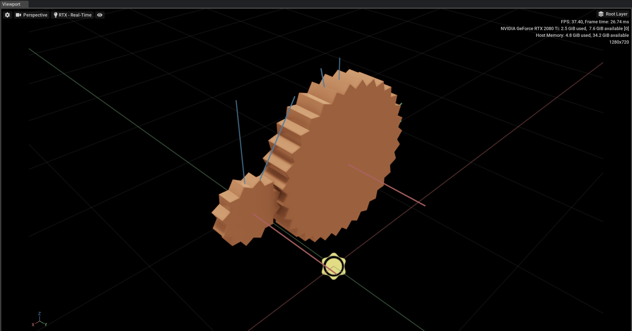
Or this gear joint:
Or this spherical joint:
Using these gizmos you increase the ability to drill down into debug data.
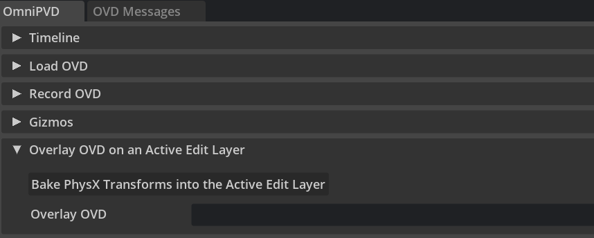
Overlaying an OmniPVD OVD File onto a USD Stage - Physics Baking#
OmniPVD supports baking PhysX simulation data onto USD Stage objects through the ovd_to_usd_over_with_layer_creation Python API exposed through the omni.physx.pvd interface. This allows the reading of a physics recording in OVD format and the baking of the transforms of objects onto Omniverse Physics objects in a separate Edit Layer, replacing the simulated objects with a set kinematic path while still allowing other physics simulated objects (added afterwards) to interact with them.
Particle position baking is also supported for both UsdGeomPoints and UsdGeomPointInstancer prims.
Note
The old UI-based baking feature has been deprecated. Use the ovd_to_usd_over_with_layer_creation API instead.
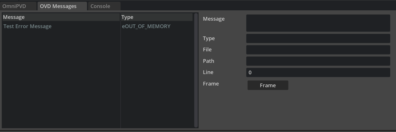
OVD Messages#
The OmniPVD API allows users to send messages inside of the object and attribute stream. These messages can contain arbitrary information strings, file name, line number and type. They are displayed in the “OVD Messages” tab and using the “Frame” button you can move the timeline to the frame where the error occurred.
Supported Geometry Types#
OmniPVD supports parsing and visualization of the following geometry types in OVD files:
Standard geometries: sphere, capsule, box, plane, convex mesh, triangle mesh, height field, tetrahedron mesh, custom geometry
Convex core geometries:
PxConvexCoreCylinder,PxConvexCoreCone,PxConvexCoreBox,PxConvexCoreEllipsoid,PxConvexCoreSegment,PxConvexCorePoint
Note
OVD files recorded with older versions that used PxCustomGeometryExtCylinderCallbacks and PxCustomGeometryExtConeCallbacks are still supported for backwards compatibility.
Direct GPU API Recording#
Data that is set via the Direct GPU API is recorded in OVD files. The following attributes are captured:
PxRigidBody: global pose, linear velocity, angular velocity, force, torque
PxArticulationJointReducedCoordinate: joint position, joint velocity, joint force, joint target velocity, joint target position
PxArticulationLink: root global pose
Simulation results when running with Direct GPU API enabled are also recorded. Note that this comes with a performance penalty.
OmniPVD Known Limitations#
At the moment, recording of simulation runs starts as soon as the simulation starts, meaning there is no way to delay, pause, or start the recording from a specific frame or simulation time. The recording starts when the simulation starts and stops when the simulation stops.
The recording system is constrained to write OVD files to disk, which must then be imported by the OmniPVD extension for visualization. There is currently no live streaming of the OVD data as it’s being produced.
PhysX tendons are currently not supported.
Regarding collision visualization, the contact forces are not displayed with gizmos.