Particles#
Omni PhysX features GPU-accelerated position-based-dynamics (PBD) particle simulation that allows you to add fluids and granular media to a scene. The particle sets can interact with all other simulation objects such as articulations, and rigid/deformable bodies. This video shows the Paint Ball Emitter demo where particle fluid balls are launched onto collider plane. It is available in the Window > Simulation > Demo Scenes window.
Note
The particle cloth feature has been removed. Cloth simulation is now provided by surface deformables. See the Deformable Migration Guide for migration guidance.
The particles schema is not finalized and may change in the future.
CPU simulation of particles is not supported, so you must have GPU simulation enabled in the Setting up a USD Stage and a Physics Scene (it is enabled by default).
For more technical background of the underlying simulation, refer to Position Based Fluids by Macklin and Müller.
Simulation Components#
A particle simulation consists of a few key components:
Particle sets representing groups of particles based on Points or PointInstancer prims; see below for steps to create them.
A particle system prim that you may create with Create > Physics > Particle System.
A PBD Particle Material that you may create with Create > Physics > Physics Material, or add to an existing material using Add > Physics > PBD Material (in this menu, you may also find parameter presets for water and viscous fluid).
The particle sets are associated with a particle system, which has attributes that define simulation behavior that is common across all its particle sets. Additional simulation parameters are provided by the PBD Particle Material that is bound to the particle system as a physics material. The PBD material attributes are also shared between all particle sets associated with the particle system.
Multiple particle systems per stage are supported; however, particles in different systems cannot collide with each other.
Note
In a future version of this feature, per-object materials will be supported.
Particle System Configuration#
Many simulation parameters are attributes of the particle system or its bound PBD particle material. For information about most of these attributes, we refer to their Tool Tips. However, the various contact and rest offsets that the user should configure can be difficult to grasp from the descriptions alone, so we add further information here. First, we consider
Particle-Particle Interaction#
For solid particles, the parameters can be sketched (in 2D) as follows:
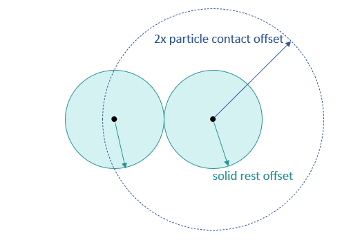
First, the size of solid particles is governed by the Solid Rest Offset parameter: Two solid particles are touching when their centers are two times Solid Rest Offset apart. The same distance also defines when fluid and solid particles are touching. In particular, the Fluid Rest Offset only affects fluid particle-particle interaction as follows:
The Fluid Rest Offset cannot be considered to be the radius of a fluid particle as with solid particles. However, the radius is used together with the particle mass to determine the rest density of the fluid that the solver uses as a target density (i.e. constraint density).
The simulation generates a neighborhood for each (fluid and solid) particle, and two particles are neighbors if their distance is less than two times the Particle Contact Offset. The solver limits the number of particles that can be in a given particle’s neighborhood via the maxNeighborhood parameter (defaults to 96). In the neighborhood of a particle, constraints are evaluated by the solver, e.g. contact constraints for solid particles, or density constraints for fluid particles.
Particle-Non Particle Interaction#
The Contact Offset and Rest Offset parameters of the particle system work analogously to the rigid- and deformable-body:
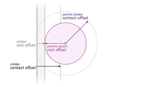
When a particle (its center) is closer to a collision geometry than the sum of the particle system’s plus the collider’s Contact Offset, contacts are generated and processed by the solver. The particle and the collider are in contact when the distance of the particle center to the collider geometry surface is equal to the sum of their Rest Offsets. Note that the Solid Rest Offset only applies to particle-particle interactions, see above, and is irrelevant for contacts with non-particle-object interactions.
Offset Autocomputation#
By default, the particle system offsets are computed from the Particle Contact Offset which defaults to 0.05 meters scaled to scene units. Therefore, you best change the resolution of a particle set by adjusting the Particle Contact Offset, as the other offsets follow. Since we cannot currently display the autocomputed values to the user in the UI, here are the formulas we use under the hood to compute the offsets:
Parameter |
Autocompute Value |
|---|---|
Contact Offset |
1.0 * Particle Contact Offset |
Rest Offset |
0.99 * Particle Contact Offset |
Fluid Rest Offset |
0.99 * 0.6 * Particle Contact Offset |
Solid Rest Offset |
0.99 * Particle Contact Offset |
Creating Particle Sets#
Particle sets are used to simulate fluids or granular material like sand. The particle positions are set up using either a Points or a PointInstancer prim.
You can set up the particle positions in the Points or PointInstancer using Python code, for example running a script in the Window > Script Editor, and you may refer to the Isosurface Fluid Demo for sample code. Another option is to use the Particle Sampler to create particles from meshes, see below.
After setting up the Points or PointInstancer, select Add > Physics > Particle Set in its Property Window, and configure the set in the new particle-set rollout. In particular, set up the relationship to the particle system that the set belongs to. Most parameters defining particle behavior (i.e. dynamics) are attributes of the particle system and the PBD particle material bound to it, see Particle System Configuration.
Particle Sampler#
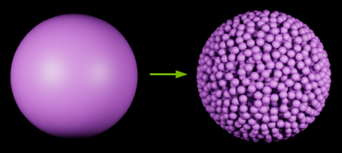
You may create Points-based particle sets by sampling the surface or volume of a source mesh. Select the source mesh, and do Add > Physics > Particle Sampler. See the note below about a current visibility issue with the created particles.
The sampler then performs the following steps:
If there is no particle system on the current stage, creates a new particle system with default settings.
Auto-computes a suitable (sampling) Particle Distance from the Fluid Rest Offset in the particle system offset values.
Checks if there is already a suitable Points prim to inject sampled particles. If not, a Points prim with a particle set component (fluid default) is created. If possible, particle set prims are shared among multiple particle samplers.
Listens to changes that may affect the sampling result and re-samples the generated points. Resampling triggers include:
setting a specific Particle Distance, or toggling Sample Inside Volume on the source-mesh Particle Sampler properties
unchecking the Fluid checkbox in the generated Points’ Particle Set properties (because the Fluid Rest Offset and Solid Rest Offset may result in different values for the auto-computed Particle Distance)
transform changes on the source mesh
You may stop the automatic resampling by either deleting the source mesh or its sampler component, or removing the relationship to the created Points in the sampler component.
Note
Due to an issue with the rendering pipeline (to be fixed), the sampled particles are not visible until you trigger an update by toggling a render-related setting of the created Points, e.g. toggle the Cast Shadows checkbox in the Geometry/Mesh rollout of the Points.
Note
Particle Set lifetime management: Deleting a sampler will remove the particles this sampler generated from the prim, and if all the samplers sampling into the same prim are deleted, the particle prim will also be deleted (before: particle prim stayed there.)
Note
Removing samplers while keeping sampled particles: This can be cumbersome due to the automatic lifetime management. A workaround is to duplicate the particle set prim and then remove the samplers (the original particle set prim will be removed automatically.)
Debug Visualization#
The particle debug visualization is available in the viewport show/hide options (the eye) and allows inspecting particle sets, and the various offsets of the associated particle system in particular.
Here is a slideshow of the particle-set visualization options on the Fluid Isosurface demo available in the Demo Scenes which uses Isosurface postprocessing to visualize the fluid as a solid mesh:
The particles shown in the slideshow are set to have a radius of Fluid Rest Offset, but you may change the debug-visualization particle radius to another offset in the Physics Debug Window (Window > Simulation > Debug):
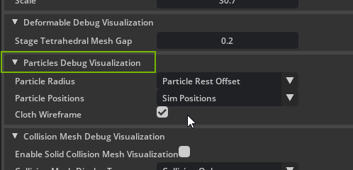
Note that Particle Rest Offset will automatically choose the correct offset (i.e. Fluid or Solid Rest Offset) based on the particle object.
Overriding Material Density#
You can change the default material density by binding a PBD Particle Material to the Setting up a USD Stage and a Physics Scene or Particle System. By default, the mass of the particle set is computed using the material density. However, the user can override this by adding a Mass component (Add > Physics > Mass) to a particle set. In summary, the order of precedence is:
Default 1000kg/m3 < Material density (Physics Scene) < Material density (Particle System) < Mass-component density < Mass-component mass
Particle-Set Mass Computation#
If the mass attribute is set, the mass of each particle in the set is computed by dividing the value of the mass attribute by the number of particles in the set.
computedMass = mass / numParticles
If the density attribute is set, the mass of each particle in the set is determined by using the density and rest offset volume. For a solid particle-set, the solid rest offset is used. For a fluid particle-set, the fluid rest offset is used.
Solid Particle Set (we assume the particle is a cube)
computedMass = 8 * solidRestOffset^3 * density
Fluid Particle Set (we assume the particle is a cube)
computedMass = 8 * fluidRestOffset^3 * density
Post-Processing for Fluid Rendering#
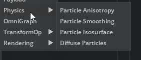
There are several particle-set post-processing features that can improve the appearance of fluid particle sets. The features only affect the render output, and have no effect on the underlying simulation, i.e. particle dynamics. You can add each component through the Add > Physics menu in the property window of the particle system:
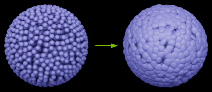
Smoothing#
As the name implies, this step smooths the particle positions depending on the user-set strength.
Anisotropy#
Anisotropy uses data computed by the solver to stretch the particle spheres into ellipsoids such that the fluid surface appears smoother. Note that only the PointInstancer prim supports nonuniform scaling, and, therefore, a Points prim is auto-converted to a PointInstancer if you add anisotropy to the particle system of a Points-based set.
Isosurface#
The isosurface post-processing component extracts a render mesh from the (fluid) particles in the particle system:
In addition to configuring the isosurface extraction in the rollout added to the particle system’s properties, you may add a render material to the particle system to control the appearance of the extracted mesh.