2.5. Add Camera and Sensors
Omniverse Isaac Sim provides a variety of sensors that can be used to sense the environment and robot’s state. In this tutorial, we will cover the simple example of attaching a camera sensor to our mock robot, a process that can be generalized to other sensors. Details regarding the camera and other types of sensors can be found in our Advance Tutorials and Sensor Extensions under Manuals.
2.5.1. Learning Objectives
This tutorial details how to
Add cameras
Attach cameras to geometries
2.5.2. Getting Started
Prerequisites
Complete the Introductory Tutorials and the previous tutorial in the GUI Tutorials, as well as the introduction to camera frames and axes.
Note
We recommend starting this tutorial using the Isaac/Samples/Rigging/MockRobot/mock_robot_rigged.usd file provided to have a standardized setup.
2.5.3. Adding Camera
To add a camera, go to the Menu Bar and select Create > Camera. A camera will appear on the stage tree, and a grey wireframe representing the camera’s view will appear on the stage. You can move and rotate the camera’s transform just like any other objects on the stage.
You can also add a camera by moving the current view in the viewport to a view of your choosing, and then go to the Camera button on the upper left hand corner of the viewport display, and select Camera > Create Camera from View. A new camera should appear on the Stage tree, as well as the list of cameras that can be selected in the Camera button.
2.5.4. Camera Inspector Extension
Once our cameras are added in the scene, we can use the Camera Inspector Extension to manage our cameras. The Camera Inspector Extension allows us to easily create multiple viewports for each camera, check camera coverage, as well as get/set camera poses in the desired frames.
2.5.4.1. Launching Extension
To open the Camera Inspector extension, go to the Menu Bar and select Isaac Utils > Workflows > Camera Inspector.
After launching the extension, we should be able to see our camera selected already in the dropdown. When we add a new camera, be sure to click the Refresh button to ensure that the extension finds this new camera.
2.5.4.2. Camera State Textbox
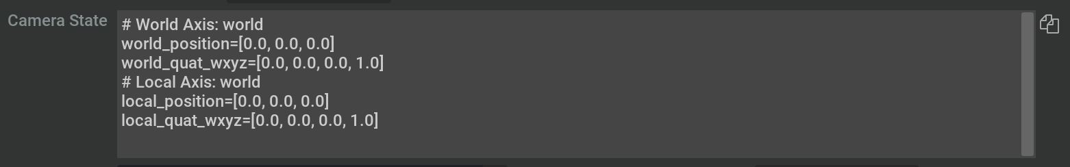
The Camera State textbox near the top of the extension provides a convenient way to copy the position and orientation of your camera directly into code. Simply click the copy icon on the right of the textbox to copy to your clipboard.
2.5.4.3. Creating Viewport
With our camera selected, we can create a new viewport for our camera. To do so, click on the ‘Create Viewport’ button to the right of the camera dropdown menu.
By default, this creates a new viewport and assigns the current selected Camera to it. We can assign different cameras to different viewports using the two dropdown menus and buttons in the extension:

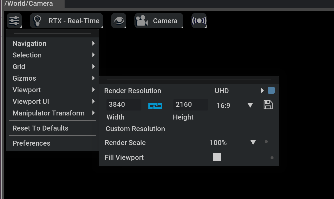
After launching our viewport, we can also change the resolution using the menu in the top left and going to Viewport. When changing the resolution, please note that Omniverse Kit only supports square pixels. This means that the resolution aspect ratio must be the same as the aperture ratio.
2.5.4.4. Camera Status Panel
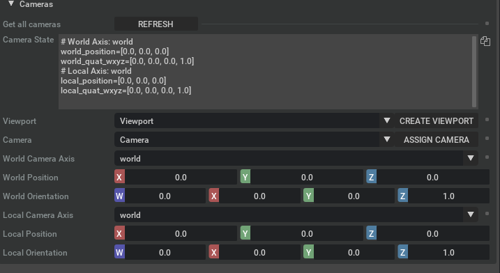
Below the camera and viewport dropdown menus is the camera status panel.
This panel displays the location and orientation of the camera in both the local coordinate system and also the world coordinate system. By default, it displays the coordinates in the World Axis. However, using the Camera Axes dropdown, this can be changed to be in the USD Axis or the ROS Axis.
The camera status panel will update automatically if the camera is moved in the stage using the gizmo. It will also update if the location or orientation of the camera is updated in the property panel.
2.5.5. Attach Camera to Robot
Let’s first rename the newly added camera to car_camera so we can keep track of it.
It would be easier to place the camera if we could see both the desired camera input stream, as well as where it is relative to the robot from an outside camera. Open up a second viewport window by going to the Menu Bar and click Window > Viewport > Viewport 2. A new viewport appears; dock it wherever you’d like.
Keep one of the viewport in Perspective camera view, and change the other one to car_camera view. Find the Cameras menu on the top edge of the viewport, and switch to Camera > car_camera. Now we can have both the view of the onboard camera, as well as an overview of the scene.
Attach the camera to the robot’s body by dragging the prim under
body. Now the camera will move together with the body. You may need to switch the camera view for the viewport again.Let’s point the camera slightly down and make it face forward so we can see the car as well as the ground. Set the camera transform translation to
x=-0.6,y=0,z=2.2, orientation tox=0,y=-80,z=-90and scale tox=1,y=1,z=1. You should see the viewport showing the onboard camera view splitting the window between the robot’s body and the ground and the relative position and orientation of the camera to the robot in the Perspective camera viewport.Press Play. The camera onboard the robot should now move with the robot.
A similar strategy is used to apply other onboard sensors.
Important
If the view of the camera is moved while displaying, it will change the camera’s properties. Instead, affix a prim to the parent with the correct offset, and then affix the camera to that new prim. Then, if the camera position is accidentally moved, it can be reset by zeroing all its position and orientation parameters relative to the prim, which cannot be easily changed.
2.5.6. Summary
In this tutorial, we learned how to use the Camera Inspector Extension. Additionally, we also learned how to add a camera to the robot.
2.5.6.1. Next Steps
Continue on to Interactive Scripting to learn how to run python APIs inside the GUI.
For rigging a more complex robot, go to Rigging Robots.
2.5.6.2. Further Reading
More about Cameras
Tutorials about using other types of sensors Using Sensors: LIDAR and Using Sensors: Generic Range Sensor,