Factory-Level USD Structuring#
Note
This guide presents opinionated recommendations for structuring USD content at factory scale. The patterns described here prioritize scalability, multi-domain reuse, and lifecycle management—requirements common to large industrial digital twins. Individual projects may warrant different approaches based on specific constraints and use cases. Please also read Asset Structure Performance Optimizations and Tradeoffs for more information on structural optimization choices.
This guide builds on OpenUSD fundamentals covered in the OpenUSD Developer certification.
This guide explains how to structure factory-scale USD content so you can scale reuse, maintain clear ownership boundaries, and support downstream simulation workflows. You learn a progressive, seven-step pattern that transforms monolithic exports into modular, instancing-friendly assemblies.
Three Pillars of Factory-Scale USD#
Digital twin projects often succeed in pilot phases but encounter challenges at scale. When data arrives from multiple tools, suppliers, and continuous updates, unstructured content becomes ungovernable. Factory-scale USD structuring rests on three fundamental pillars:
Assets
Structuring content as discrete, reusable assets enables lifecycle management—equipment revisions, supplier updates, and engineering changes propagate through the system without forcing full re-export. Assets become the unit of versioning, validation, and optimization. Domain-specific data (physics, semantics, sensors) layers onto assets non-destructively, transforming them into SimReady components.
Aggregation
Assets compose into assemblies—work cells, production lines, and complete factories. Aggregation leverages USD’s composition engine to reference and instance assets without duplication. Aggregates themselves can become assets with their own lifecycles, enabling hierarchical management from individual equipment to entire facilities.
Animation and Simulation
Proper structure enables animation and simulation workflows to interact with digital twin data through clearly defined interfaces. Animation separates from geometry, allowing scenario switching and timeline manipulation. Physics simulators, robotics environments, and AI training pipelines rely on stable prim paths and composition patterns—structure creates the contracts these tools require.
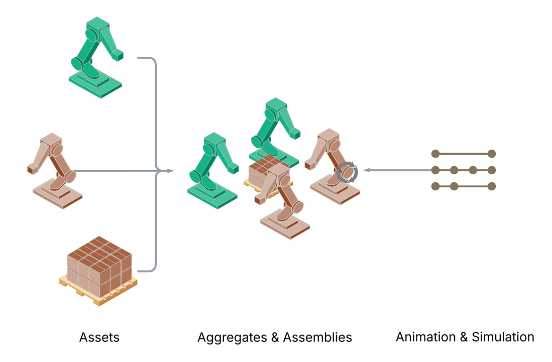
The three pillars: Assets compose into Aggregates and Assemblies, which expose interfaces for Animation and Simulation.#
Zooming In: Applying USD Structuring Concepts#
The following sections walk through a progressive structuring approach that implements these pillars. Starting from an assumed “monolithic export” (a single USD layer representing an entire factory), each step transforms the content into a composition-driven assembly—built from reusable component assets, shared material libraries, and externalized animation layers.
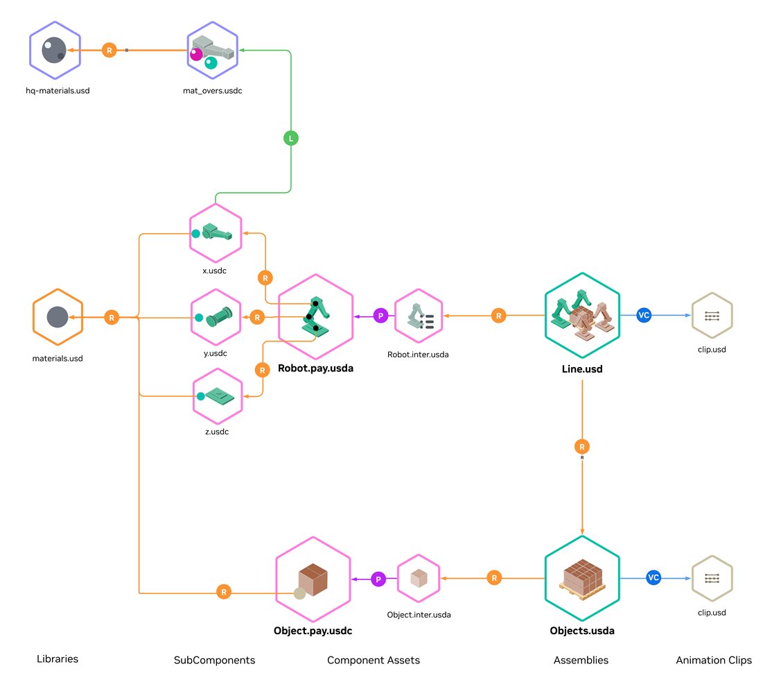
The target: a structured factory assembly composed from reusable component assets, material libraries, and animation layers.#
Diagram Legend: The diagrams in this guide use the following notation for USD composition arcs:
R — Reference
P — Payload
VC — Value Clips (metadata)
L — Sublayer
Step 1: Separate Animation#

Animation layered on top of geometry as value clips, enabling reuse and timeline manipulation.#
The first step is to separate animation from the main stage. Animation should be authored separately from geometry and assembly structure.
Key practices
Value clips — Separate baked animation into value clips.
External authoring — Author animation in external processes and bind at assembly time.
Targeted binding — Apply clips to individual references or payloads rather than the entire stage.
Why It Matters
Scenario switching — Swap clips to visualize different production scenarios without modifying geometry.
Timeline control — Loop, reverse, or time-stretch animations independently of the scene.
Independent optimization — Tune animation and geometry detail levels separately.
Asset replacement — Upgrade assets without re-authoring motion data (provided hierarchies match).
For more information on animation workflows, see the VFI Animation Workflow and Supporting Scripts section.
Step 2: Identify Asset Boundaries#

Component asset referenced into a factory assembly stage.#
See also
With animation separated, the next step is identifying where to draw asset boundaries. Assets should align with real-world units that are versioned, sourced, or updated independently.
Key factors for drawing boundaries
Lifecycle and Ownership
Content with different update cycles or ownership should be separate assets. Consider: Who updates this content, and how often?Equipment
Robots, conveyors, machines, and fixtures typically map to individual component assets. Each can be versioned and replaced without affecting the rest of the factory.Facility Sections
Work cells, production lines, or building zones can be grouped as assembly assets that reference equipment components.Shared Resources
Material libraries, animation clips, and sensor configurations are assets in their own right—referenced by multiple equipment or facility assets.Instancing Potential
Repeated elements (identical robots, racks, fixtures) benefit from being defined as discrete assets that can be instanced. Assets that appear multiple times should share a common definition.Validation and Optimization Scope
Structure defines the granularity at which validation and optimization can operate. Assets that require independent geometry repair, decimation, or material consolidation should be separated. Once assetized, these operations can run in parallel across the asset library.Selective Loading
Large facility sections or heavy equipment benefit from payload boundaries that enable selective loading. Content that users may want to load or unload independently should be a separate asset.
Tip
For Pipeline and Converter Developers
Effective structuring begins upstream. Work with content authors to define asset boundaries in the source application—converters cannot infer boundaries that do not exist in the source data.
Converters and export pipelines should preserve metadata that enables downstream structuring—even when full assetization is not performed at conversion time. Useful breadcrumbs include:
Meaningful Kind Hierarchy
Assign USDkindvalues (component,subcomponent,assembly) to reflect the logical structure of the source data. See Model Hierarchy and Organizing Prim Hierarchy.Asset Info Attributes
PopulateassetInfowith identifiers, version strings, or PLM tracking data that link USD prims back to their source definitions.Custom Attributes for Unmapped Data
Data that cannot be mapped to existing OpenUSD schemas (part numbers, supplier codes, classification tags) should be authored as custom attributes with clear vendor prefixes (e.g.myCompany:partNumber) rather than discarded.Deduplication and assetization granularity
When identifying asset boundaries, detect and eliminate duplicate geometry, materials or textures during or after export. Deduplication directly informs the right level of granularity—assets that share identical geometry and materials should reference the same subcomponent rather than carrying redundant copies. This is often the highest-impact cleanup step before instancing can take effect.
This metadata enables automated restructuring tools to identify asset boundaries, match repeated geometry for instancing, and trace content back to authoritative sources.
For more on building export pipelines, see Data Exchange, Conceptual Data Mapping, and the USD Exchange SDK.
Why It Matters
Asset boundaries define the units of change management in your digital twin. Well-drawn boundaries transform a static export into a living asset library that evolves with your facility—enabling independent versioning, parallel team workflows, granular validation, and instancing.
Step 3 (Optional): Interface/Payload Layering#

Component asset structure: Robot.inter.usda (interface layer) references Robot.pay.usdc (payload with geometry).#
This pattern is optional and is most useful in larger assemblies that benefit from selective loading and stable public composition targets.
Once asset boundaries are identified, assets can be structured with a clear separation between public interface data and heavier content. A component asset is a reusable unit (for example, a robot or conveyor).
Key practices
Interface Layer — Defines the public surface of the asset (
kind,assetInfo,extent hints,variant sets). It remains available when payloads are unloaded.Payload — Contains heavy geometry and internal hierarchy. Enables selective loading.
Granularity tradeoff — Finer asset/layer boundaries can improve lifecycle and selective-loading control, but they can also increase layer count and open/stat latency. For deployment-time tradeoffs, see Asset Structure Performance Optimizations and Tradeoffs.
For detailed guidance, see Asset Interface and Reference/Payload Pattern.
Tip
Pre-structured assets—such as a SimReady Prop asset or an Isaac Sim Robot asset—can be referenced directly at component boundaries without further restructuring.
Why It Matters
Selective loading — Navigate entire facilities while keeping heavy geometry unloaded.
Stable composition targets — Interface provides consistent prim paths even as payload internals evolve.
Memory efficiency — Load only what you need; unload distant assets without losing scene graph presence.
Faster iteration — Modify asset internals without invalidating upstream references.
Step 4: Enable Instancing#

Robot component composed from instanced rigid subcomponents (x.usdc, y.usdc, z.usdc) assembled through the payload layer.#
See also
With assets structured as discrete references, instancing can now be applied. Instancing is a core requirement for scalable factory scenes, but it must be applied with care. For background, see What is Instancing?
In OpenUSD, instances are immutable—attribute opinions (including animation) cannot be applied on prims inside an instance. As a result, instancing granularity must follow opinion authoring granularity.
Key practices
No whole-asset instancing for articulated objects — The entire robot cannot be instanced if its parts need animation.
Instance at rigid-body level — Instance each animatable rigid body (individual links), including geometry and materials.
Reassemble through references — Combine instanced subcomponents into the full component.
Choose internal vs external referencing — External referencing allows for maximum reuse of subcomponents across components, but it can substantially increase layer count. Internal referencing keeps layer count low, but doesn’t facilitate sharing of subcomponents between components.
For implementation details, see Authoring Scene Graph Instancing.
Why It Matters
Memory reduction — Hundreds of identical robots share geometry in GPU memory.
Render performance — Instanced draws are orders of magnitude faster than unique submissions.
Animation compatibility — Instancing at rigid-body level preserves joint animation while sharing geometry.
Consistent updates — Fix a mesh defect one time, and every instance reflects the change.
Step 5: Organize Materials into Libraries#

Canonical material libraries referenced and instanced across factory components.#
See also
Materials should be treated as reusable assets in the same way as geometry.
Key practices
Shared libraries — Define canonical materials in shared material libraries.
Interface exposure — Lift shader attributes into material interfaces.
Reference, do not duplicate — Reference and instance materials rather than duplicating them.
Binding with geometry — Let material bindings travel with subcomponents where appropriate.
Why It Matters
Consistency — All “safety yellow” surfaces match across equipment from different suppliers.
Efficient updates — Adjust a prototype one time, and the change propagates everywhere.
Reduced shader compilation — Shared materials compile one time, improving load times.
Design iteration — Swap material libraries without touching asset files.
Step 6: Layer Domain-Specific Data#
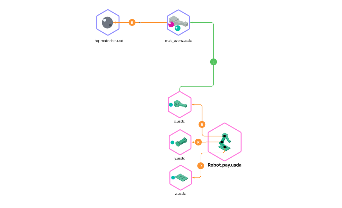
Domain-specific layers (here: material specialization) applied as edit layers on top of structured assets.#
Well-structured assets enable downstream workstreams to layer domain-specific data through USD composition—without modifying source assets.
Key practices
Dedicated layers per domain — Each team authors in their own layer file.
Target stable prim paths — Layer onto interface prims that will not change as payloads evolve.
Non-destructive composition — Override attributes, and do not modify source assets.
Common examples include material specialization, physics properties, sensor definitions, and semantic labels.
Tip
This layering step is where structured assets become simulation-ready. By adding physics properties, semantic labels, and sensor definitions, assets meet SimReady specifications.
Why It Matters
Parallel team workflows — Simulation, perception, and visualization teams work independently.
Non-destructive iteration — Experiment without risk to base geometry.
Clear ownership — Each layer has a responsible team; changes are traceable.
SimReady transformation — Progressively enrich assets to meet simulation requirements.
Step 7: Object Handling#

Object handling structure: Objects.usda contains the Point Instancer referencing Object.inter.usda (interface) which payloads Object.pay.usdc (prototype geometry). Animation is driven through value clips (clip.usd).#
Object handling—also called movable objects or material flow—addresses how production parts move through a factory over time. OpenUSD has no native mechanism for dynamic re-parenting, making this a data modeling challenge.
Why It Matters
Object handling is often what stakeholders want to see first—products moving through the line proves the digital twin is alive. Point Instancers handle millions of products with minimal overhead, can be driven by simulation or recorded data, and decouple flow animation from equipment assets.
Point Instancers for Object Handling#
A factory may handle thousands or millions of identical objects simultaneously. In OpenUSD, this repetition is modeled most effectively with Point Instancers.
Recommendation: Represent large populations of movable products with Point Instancers and drive motion over time, rather than duplicating product prims, swapping visibility, or attempting to dynamically restructure the prim hierarchy.
A Point Instancer is a USD prim that efficiently renders many copies of prototype geometry at different positions, orientations, and scales. Instead of creating thousands of individual prims, a single Point Instancer holds arrays of transforms and references one or more prototype prims. The renderer draws the prototype at each transform location, achieving massive scene populations with minimal scene graph overhead. Transforms can be animated per-frame, enabling object handling visualization without hierarchy changes. For implementation details, see Authoring Point Instancing.
Key Attributes
Positions, Orientations, Scales
Arrays with one entry per instance slot, time-sampled to animate movement. Products flow through the factory as these values change each frame.InvisibleIds
Array of instance indices hidden at each frame. This handles products entering and exiting the scene.Instance Pooling
The number of instance slots can be less than the total number of products over time. When one product exits and another enters nearby, they share the same slot—reducing instance count while maintaining visual continuity.
Alternative Approaches#
Different scenarios call for different representations.
Physics Joints and Constraints
Use when the carried/attached relationship must be physically simulated (gripping with contact constraints, physically meaningful coupling). Tradeoff: heavier runtime semantics, not appropriate for millions of kinematically moving flow items.
Referenced Prims
Use when each movable object needs richer authored structure, individual identity, or unique overrides (annotations, per-object variations). Tradeoff: for high counts, becomes expensive (scene graph size, load time, memory). Handoff logic may tempt fragile re-parenting or visibility tricks.
Common Pitfalls#
Warning
Over-Structuring Beyond Useful Granularity
Very fine-grained structure increases the number of layer files and references to resolve, which can hurt startup latency. Fine-grained authoring structure is valuable for lifecycle management but may require a packaging step to consolidate layers for runtime. See Asset Structure Performance Optimizations and Tradeoffs for that packaging step.
Treating Instancing as Optional Optimization
At factory scale, repetition dominates scene size. Design instancing into asset structure from the start rather than attempting to add it later.
Expecting Instancing Without Composition Boundaries
OpenUSD instancing requires composition arcs. First create repeatable references and payloads through modular asset structure, then apply instancing at those boundaries.
Discovering Instance Immutability Too Late
Descendants of instanced prims become read-only. Choose instance boundaries based on where edits (animation) must land. When edits target sub-parts, instance at deeper granularity or use refinement patterns.
Mapping CAD Structure Directly to Instance Boundaries
USD instancing differs from CAD instancing. Instancing an entire articulated asset blocks edits to joints, visibility, or annotations. Instance rigid subcomponents and reassemble through references.
Baking Animation Into the Main Stage
Coupling motion with structure amplifies edit targeting problems. Externalize time-varying data into clips and layers, binding through composition at valid authoring targets.
Choose Suitable USD Formats
USDZ packaging and ASCII for USD data with large arrays kills performance. Use binary USD files for layers with geometry and other “heavy data”. ASCII layers are acceptable for sparse layers such as asset interfaces. For extra performance benefits, use the corresponding USD file extension over the generic .usd extension as this will save an extra file “stat” by USD before layers are opened for composition.
Expecting Exporters to Produce Structured USD
Exporters may produce output that does not map to factory scale structuring requirements. Plan for a shared cleanup stage (validation, optimization, restructuring).
More fundamentally, assetization must begin upstream—in the source application—not just at export time. If the source tool does not distinguish assets from arbitrary geometry groups, the exporter cannot infer asset boundaries. Work with content authors to define assets in the source environment, then ensure the export pipeline preserves those definitions.
Duplicating Materials at Scale
Authoring materials per mesh or per instance creates massive material counts. Canonicalize materials into libraries and reference them as reusable assets.
Duplicating Product Assets for Object Handling
Creating multiple copies of the same part and switching visibility to fake movement. This approach does not scale and creates maintenance burden. Use Point Instancers instead.
Conclusion#
You have applied a factory-scale USD structuring pattern that separates animation, defines asset boundaries, enables instancing, and supports layered simulation workflows. This structure helps you scale updates and performance without sacrificing maintainability.
Downloadable sample assets that conform to this guide are planned. For now, the USDA snippets in VFI Asset Structure Examples serve as the reference implementation.
For concrete layer snippets that map to each step, see VFI Asset Structure Examples. For deployment-time packaging tradeoffs, see Asset Structure Performance Optimizations and Tradeoffs.