USD Structure and Assembly#
At the heart of USD is its composition engine. A virtual world in OpenUSD is represented as a composed stage.
Prims are organized hierarchically. The composition engine allows various composition arcs, such as references, payloads, and variants, to be applied to any prim in any combination, resolving the resulting scene graph in a predictable way. A significant advantage of this system is the ability for stronger opinions in certain layers to non-destructively override scene descriptions from weaker opinions in other layers. For example, changing the material color of a robot within a factory layout scene does not modify the original referenced robot asset file. Aggregate datasets, such as a work cell or a section of a production line, can themselves be aggregated into larger datasets, ultimately forming the complete factory digital twin. This hands-on section demonstrates the foundation of scalable digital twin workflows. The manual assembly operations shown here translate directly to automated pipelines suitable for processing hundreds of components—the VFI Samples repository provides programmatic implementations.
Example#
In a factory digital twin with 500 identical robots, effective use of instancing requires selecting the correct structural granularity.
Rather than instancing the entire robot articulation, each robot instance maintains its own non-instanceable articulation root and joint hierarchy to support independent animation, control, and physics simulation. Instancing is instead applied at the component and link level, where rigid geometry, mass properties, and visual detail are identical across robots.
In practice this means:
Each robot has a unique articulation root and joint structure.
Individual robot links reference shared link assets (for example,
Link_A.usd) withinstanceable = true.Repeated subcomponents such as fasteners, housings, and sensors are also instanceable.
OpenUSD creates prototypes for these shared link and component sub-hierarchies.
All robots share link-level prototypes in memory while maintaining independent joint state and simulation behavior.
Traversal and memory cost scale with the number of unique link and component prototypes, not with the total number of robots.
For more information about this approach, see: Isaac Sim Asset Structure <https://docs.isaacsim.omniverse.nvidia.com/5.1.0/robot_setup/asset_structure.html>
The wheel assembly example in this section can leverage instancing for bolt components—each bolt would reference Bolt.usd with proper Xform-parent structure for mesh prims, enabling shared geometry while maintaining independent instance-root transforms for positioning around the wheel.
Trade-offs: Instancing substantially reduces memory footprint and evaluation cost but imposes stricter asset design requirements and limits post-import flexibility. Assets must be structured with instancing in mind from the start; retrofitting existing assets typically requires restructuring hierarchy, normalizing composition, and reassessing relationship placement.
Further reading
For restructuring large, monolithic factory stages into scalable, composition-driven assemblies, see Factory-Level USD Structuring.
Aggregation#
Let’s take the individual pieces that we have set up and aggregate them into a wheel USD file.
Create a new file: File -> New From Stage Template -> Empty.
Select the World prim. In the Property panel, set its Kind to component.
To be able to see better, change the light mode from Stage Lights to Grey Sky.
From the Content Browser, drag and drop all the parts onto the World prim.
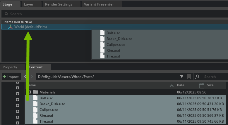
Save the file to the root of the Wheel directory and name it
Wheel.usd.
We will manually position the components. At facility scale, PLM data is typically written to CSV or JSON to be parsed and automated via Python. This progressive approach—manual operations for learning, programmatic operations for scale—reflects real-world adoption patterns.
The VFI Samples repository provides production-ready implementations of these workflows, demonstrating:
Automated component positioning from configuration data.
Validation-driven optimization (quality gates automatically select presets based on detected issues).
Payload-based assembly creation suitable for continuous integration pipelines.
These automated workflows implement the same composition patterns shown in this tutorial, enabling teams to scale from pilot projects to platform capabilities. This will be demonstrated in the workflow iteration cycle automation section.
Select the
/World/Brake_Disk/Disk_Brake_1021Xform. Before you move it, switch to the Layer panel. Notice that we only have the payloads of the components and nothing else.Now, move the Xform forward on the X axis to 14.0. Do this by using the viewport transform widget: click-and-drag the red transform handle and the transform op will be created for you in the Property panel. You can also click +Add Transforms in the Property panel and type in the value - however, as of Kit 107.3.1, there is an existing defect with this method.
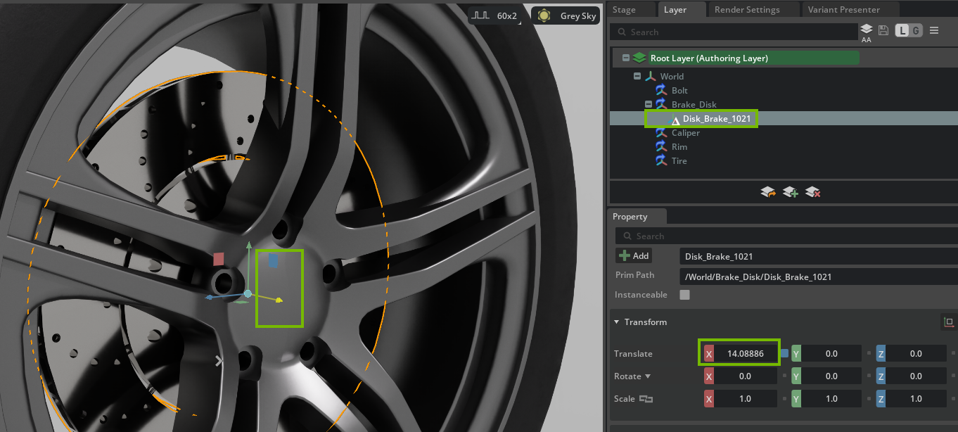
Notice how we are getting a new group in the Property window containing the Xform and a triangle in the Layer panel - this is an opinion that we have introduced by moving the disk break to a position that differs from the original location of the part.
Note
You can right mouse button (RMB) -> Delete Delta on the entry with the triangle in the Layer panel and the part will go back to its original location.
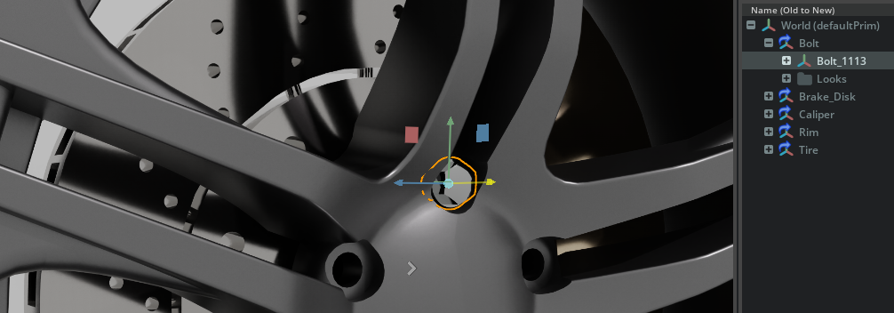
Do the same with
/World/Caliper/Caliper_8708- select it in the Stage panel and move it forward 14.0 on the X axis.For the
/World/Bolt/Bolt_1113, move it to ( X=18.0, Y=5.6, Z=0.0 ).
Next, let’s enable an extension to easily fill in the rest of the bolts, demonstrating how custom tools can extend your workflows. Alternatively, you could manually duplicate and rotate the bolts.
Go to Developer -> Extensions and search for Array Tool. Install it if not installed, then enable it. You can also set it to autoload if you want it enabled at all times.
Select the top level Bolt payload prim (
/World/Bolt), then click Tools -> Array Tool.Set count to 5, Rotate X to 72, and under options check create copies.
Click Apply (the preview shows the result).
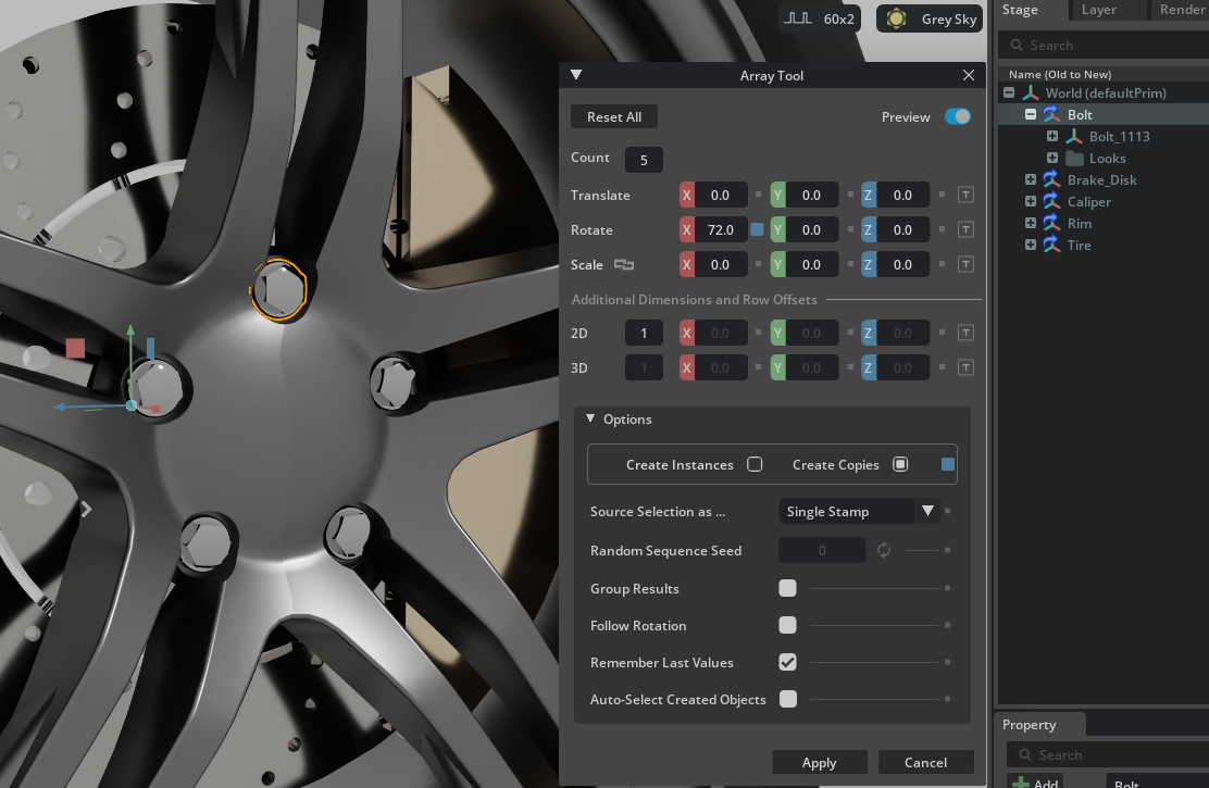
The array tool is a sample extension that demonstrates how you can enhance a workflow with custom tools to speed up iteration time.#
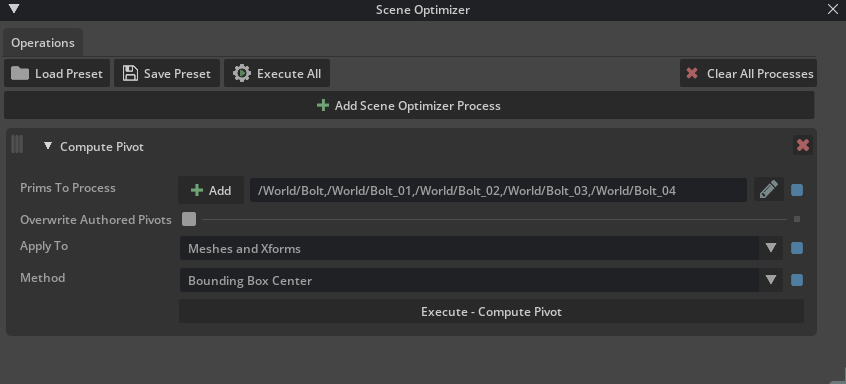
Now that we used an offset pivot for authoring, let’s fix the pivots by going to Window -> Utilities -> Scene Optimizer.
Click + Add Scene Optimizer Process -> Stage -> Compute Pivot. The processor will be added to the bottom of the stack if you have processors there already.
Set:
- Apply to Meshes and Xforms
- Method to Bounding Box Center.
- Prims To Process, select all the Bolt payloads, then click the + Add to limit the compute pivot process to the selected prims and their sub hierarchies.
- Click Execute - Compute Pivot.
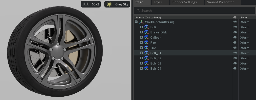
Notice how each pivot is now in the center of each respective bolt geometry.
Save the file.
We now have a component file that we can drop into a stage that can aggregate many of these wheels.
Sublayer#
Sublayers are an important concept for understanding stage transformations in OpenUSD. A stage can be built from multiple layers, including sublayers, each containing specific data or transformations such as geometry, materials, or transforms. When another layer subscribes to a sublayer, it is set up to reference or include that sublayer, so any changes made—such as updates from a new CAD conversion—are automatically reflected wherever the sublayer is used.
This approach enables efficient, automated updates throughout your pipeline. While this method offers greater flexibility, it may require additional data management to ensure these data layers remain up to date when your source data changes, for example, through re-conversion from CAD.
In the same
Wheel.usdfile, go to the Layer panel and click Create Sublayer.
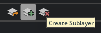
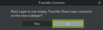
Name the sublayer file
Wheel_Merged.usdand save it to a new folder named Sublayers within the same folder whereWheel.usdis located.Select No when prompted to transfer root layer contents to a new sublayer. We want to only store transformational data in the sublayer and not all the original content.
Double-click the
Wheel_Merged.usdlayer, or right-clickWheel_Merged.usdand select Set Authoring Layer to make it the authoring layer.
Go to Scene Optimizer and click + Add Scene Optimizer Process -> Meshes -> Merge Static Meshes. The processor will be added to the bottom of the stack if you have processors there already.
Set Merge Boundary to Root Prim and click Execute - Merge Static Meshes (no prims needs to be selected).
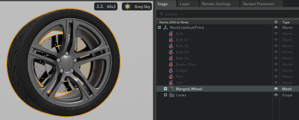
In the Stage panel, double-click on the merged mesh named “merged” and name it Merged_Wheel.
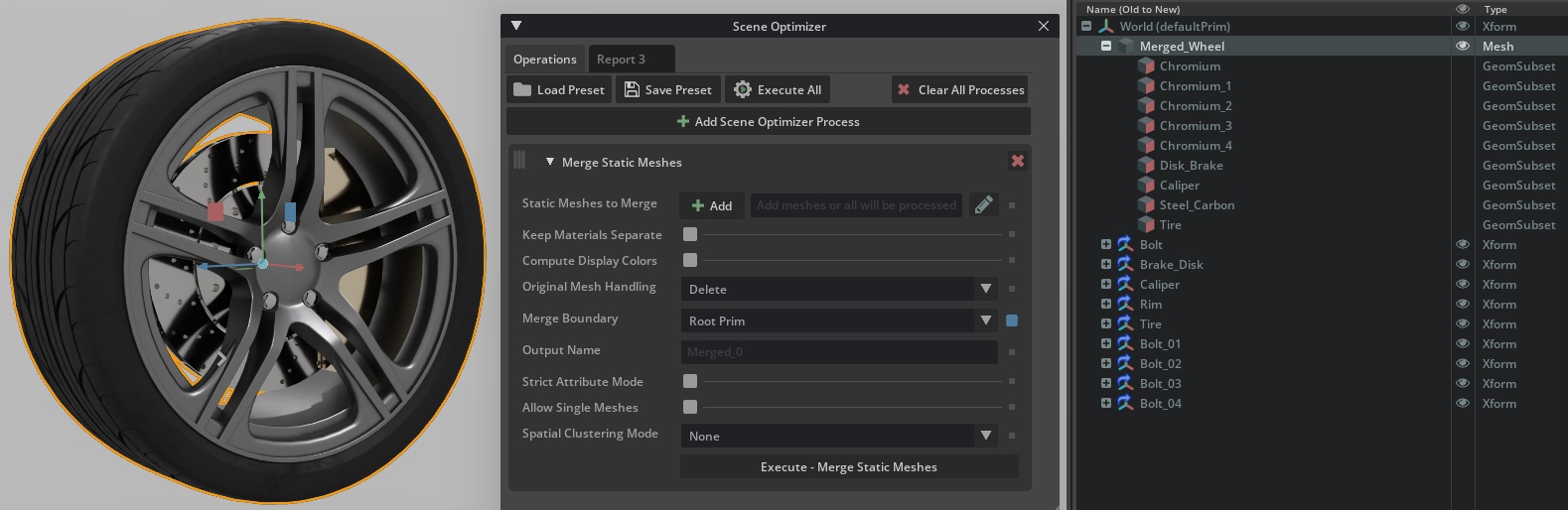
Go back to the material library we added earlier and select each GeomSubset under the Merged_Wheel prim and assign the shaders by double-clicking them from the Materials tab. For the Chromium subsets, select all of them before double clicking on the Chromium from the material library. Same thing for Caliper.
We are copying the required materials into the scope of this stage, making them directly accessible within the current USD scene file. This ensures that even after we deactivate the original payloads, the geometry in our scene will retain valid material assignments and maintain its correct appearance.When done, nothing will have changed visually, but you will have a Looks Scope under the world prim with all the materials native to this stage now.
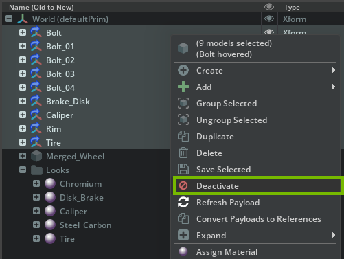
Select all the individual parts and then right-click and select Deactivate.
Go back to the Layer panel and click the Save icon to save the layer. Alternatively, right-click the Authoring Layer then click Save.
Double-click the root layer to set it back to be the authoring layer.
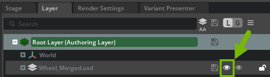
Go to the Layer panel and click the eye icon to mute the
Wheel_Mergedlayer. Inspect the stage view and notice how our original state is back.
Back in the Layer panel, click the eye icon to un-mute the layer and notice how a merged mesh is now representing the stage again.
If you remove this layer, the stage is back to its original state, and if you add the sublayer in again, you have a different representation.
This is a powerful concept that allows you to transform data in a non destructive way.
Important to note for this specific example is that if the wheel should change, you would need to re-create the sublayer, because the connection to the original data was severed when we created a new mesh representation by merging the static meshes. Because of the flexible nature of Omniverse, this can be done easily by just running scene optimizer and some Python scripts via CLI when the source data changes.
In most cases, you do not need to recreate a sublayer because it simply introduces new opinions, such as changes to properties or attributes, on existing prims by referencing their unique paths in the stage. As long as these prim paths remain unchanged, the sublayer will continue to apply its opinions correctly. This is why it is important to keep prim paths consistent when updating or iterating on your assets.