CAD Conversion Considerations#
Pre-conversion setup is key: Preparing CAD data before converting to USD is more efficient than applying post-process adjustments, which may be harder to automate.
Use chaser scripts strategically: Post-conversion scripts can automate tasks like material setup and assembly creation, but must be tailored to the target application’s workflow.
Leverage Omniverse tools: Scene Optimizer in Omniverse offers powerful options to transform data during or after conversion.
Plan for repeatable transformations: For destructive changes like mesh merging, ensure processes and mappings can be replicated automatically to support downstream digital twin workflows.
CAD to USD Organization Recommendations#
Reducing Part Count#
In CAD applications, objects are assembled from many small, individual parts. Each part would usually have one or more solid bodies. This means a product/asset may often be constructed from dozens, hundreds, or even thousands of parts.
This is usually required in mechanical engineering data as the CAD file needs to represent the product precisely, so it can be manufactured accordingly.
For many OpenUSD based use cases, however, it is more efficient to represent the asset with a smaller number of individual parts and geometries. Efficiency in this context relates to the way humans and machines alike can understand and interact with the data.
For example, a wheel may consist of dozens of parts in a CAD application; however, in OpenUSD, it is more efficient to represent the wheel with a few meshes for the rim, tire, and spokes. Consider the creation of multi bodies or merged geometries in the CAD application to achieve this.
Another potential opportunity to reduce part count is by removing internal parts which are not visible from the outside of the targeted visualized component. If that is an option, this will also have the added benefit of reducing RAM usage and speed up load times.
Tip
Consider recording a manifest of merged parts in custom attributes on the parent prim, so you can relate the USD representation back to the CAD source data.
Scene Optimizer Operations
Hierarchies Reorganization#
Related to the merging of geometries, the hierarchy of the individual asset should be considered.
In CAD applications, asset hierarchy is typically defined by how parts are assembled. In OpenUSD, it is often more useful to organize the hierarchy based on the asset’s functional features. Each prim (the basic building block in USD) on a stage is uniquely identified by its hierarchical path, which acts like a URL or URI for that prim. This path is critical because all layered composition operations in USD depend on it to correctly reference and override data.
When CAD with deep hierarchy trees get converted, the structural outcome can lead to slower traversal, increased composition cost, and reduced interactive performance. For more details, see this page.
Attempting to reorganize the hierarchy after conversion is considerably more complex and resource-intensive than preparing it beforehand. Custom Python scripts or extensions must be developed with a deep understanding of both the original CAD hierarchy and the desired functional structure. This process requires significant input from subject matter experts to accurately interpret and translate the data. As a result, post-conversion hierarchy transformation is not only more difficult to automate, but also increases the risk of errors and delays in delivering usable assets to target users.
Origins and Pivots Placement#
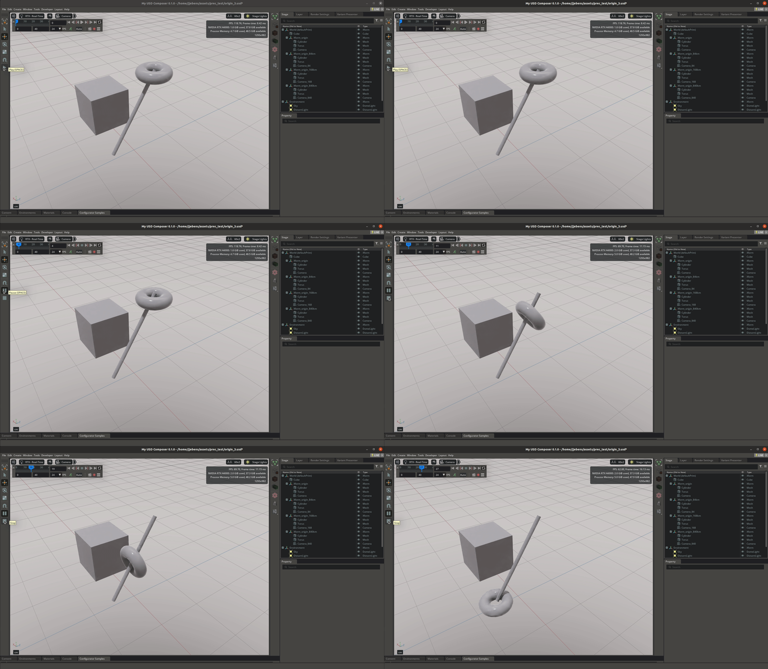
In a CAD application, the origin or the pivot point of a component is often arbitrary because the actual placement and orientation of parts within an assembly are controlled by constraints and mates (rules that define how parts fit together), rather than by the part’s own origin.
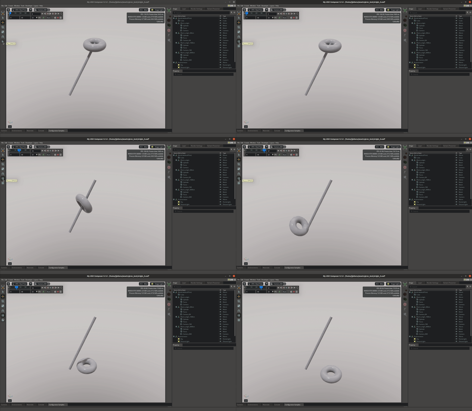
As a result, the origin may be located far from the geometry itself. When converting to OpenUSD, the component’s origin becomes the transform definition on a prim and serves as the reference point for all transformations.
It is recommended to place the origin of the part at a deliberate location, such as the center of mass or a feature of the part that may serve as the pivot for functional use.
Scene Optimizer Operations
Default Prim#
Another important aspect is the default prim which gives your assets a home path to map to when they are composed into another stage.
Scene Scale#
While working in mm scale in CAD application for manufacturing precision, keeping the same scene scale units when creating a factory digital twin is not recommended.
In USD/Kit environments, mesh vertex data is typically stored using single-precision floating-point numbers (float), whereas object transforms (position, rotation, scale) can utilize double-precision floating-point numbers (double). Single-precision floats have fewer significant digits than double-precision doubles. When objects or parts of a model are positioned at very large distances from the global origin (0,0,0) in a scene, their coordinates become very large. If the individual mesh vertices are still defined directly in these large global coordinates using floats, the limited precision of floats means that small, fine details or relative movements within that object can no longer be accurately represented.
If your entire factory digital twin is in millimeters, a 0.0001 kilometer away becomes 1,000,000 mm. If you then try to define a tiny bolt’s shape (say, details smaller than 0.1 mm) using floats at this 1,000,000 mm coordinate, the float might not have enough “slots” (significant digits) to hold both the large 1,000,000 and the tiny 0.0001 with accuracy. It effectively rounds away your fine detail which can lead to visual “jitter” or “wobbling” artifacts when you interact with or render the scene.
By setting your scene’s units to meters or centimeters, the numerical values for distances from the world origin become significantly smaller. For example, 100 meters is 100 in meters, but 100,000 in millimeters. This reduces the magnitude of the coordinates that even doubles need to handle for global placement, and more importantly, ensures that the smaller floats defining the local object geometry can do so with maximal relative precision.
The Omni Asset Validator extension contains Point Precision checkers that can warn you when the above described scenarios are detected.
For the hands on sections in this guide, a scene scale of cm and up axis Y was chosen mainly because it is the current default in Composer and it is not the same as our sample components are natively authored at.
Scene Optimizer Operations

