Asset Structure Performance Optimizations and Tradeoffs#
This page complements Factory-Level USD Structuring by focusing on performance-oriented deployment choices after a project has adopted a modular, instancing-friendly USD structure.
The guidance here highlights load-time performance (startup/open latency), runtime performance (memory footprint and interactive responsiveness), and the difference between cold and warm load behavior in real deployments.
In this guide, packaging means a deployment-time build step that combines many small USD layers into fewer, larger files while preserving scene structure and instancing behavior.
Granular authoring boundaries remain useful for reuse and instancing (memory, disk, and load efficiency), but in higher-latency environments (for example, cloud deployments), very high layer counts can increase open/stat overhead and slow startup. Packaging addresses this tradeoff by reducing layer fan-out at runtime.
Note
Case-study metrics below are anonymized and included for directional guidance.
Performance Gains (Load and Memory)#
Measured packaging choices can yield substantial gains when compared to highly disaggregated structures:
Startup: In measured scenarios, cold load improved by roughly 2–2.5× and warm load by about 4× when moving from a monolithic or highly disaggregated setup to component and subcomponent library packaging.
Memory: Process memory in the same studies dropped to about half (e.g., from ~15 GB to ~6.6 GB) when instancing was preserved and the number of layer files and references to resolve was reduced.
Layer count: Runtime layer count can be reduced from thousands to single digits for the same logical scene, reducing open/stat latency in remote or cloud environments.
The Case Study (Anonymized): Measured Impact below compares strategies; use it to set expectations and choose an approach that fits your environment.
How to Think About It#
Why This Matters#
At factory scale, teams often observe two truths at the same time:
Fine-grained boundaries and modular composition support reuse and instancing efficiency.
Very granular composition can increase the number of layer files and references the resolver must open, amplifying open/stat latency in remote or cloud environments.
The optimization goal is to keep instancing benefits while reducing composition overhead in the target runtime.
A common pattern is extraction/conversion → structuring → optimization/packaging: source extraction and conversion can produce structures that are functionally correct but not ideal for instancing or deployment. A structuring pass then introduces modular assets (per-component and per-subcomponent layers) for lifecycle and authoring benefits. Finally, an optimization pass packages those layers into runtime-oriented artifacts. The result is a “diamond” shape—narrow at source, wider during structuring, and narrower again at deployment for load performance.
Instancing Remains Foundational#
Instancing remains a baseline requirement: shared geometry and prototypes reduce memory and enable consistent updates. Instance boundaries must still align with where opinions are authored when optimizing for runtime. See Asset Modularity and Instancing (Learn OpenUSD) and Authoring Scene Graph Instancing (Learn OpenUSD).
Three-Phase Pipeline Pattern#
Treat optimization as a repeatable pipeline with distinct phases. Structuring and packaging are complementary: structuring improves modularity and instancing behavior, while packaging produces deployment artifacts tuned for runtime latency.
A three-phase pattern fits many programs:
Extraction and conversion phase — Source data is exported into USD. Output is often valid but may be structurally suboptimal for fine-grained instancing and deployment latency targets.
Structuring phase — Introduce modular assets, instancing-friendly boundaries, stable prim paths, and clear ownership.
Optimization and deployment phase — Package into runtime variants, benchmark cold and warm load, and choose packaging per environment. Build outputs can include:
Preserving interface/payload modularity.
Reducing indirection in selected layers.
Packaging components and subcomponents into shared library files.
Sharding when a single large library is not operationally desirable.
How to Do It: Tradeoffs by Packaging Strategy#
These are some examples of layer count reduction strategies, applied to the structure described in Factory-Level USD Structuring:
Reduced indirection (e.g., direct payload packaging) — Instead of referencing the component interface layer, the payload layer can be directly referenced from the assembly stage.
Internal subcomponent references — Place subcomponents directly in components and use internal referencing, rather than referencing them from a separate subcomponent layer.
Component and subcomponent library packaging
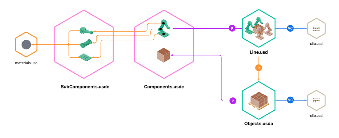
Instead of referencing components and subcomponents from many individual layers, this approach aggregates them into shared library layers and references sub-hierarchies from those libraries.
Strong reduction in the number of layer files; often the largest startup gains in remote or cloud setups where latency is a critical factor.
For concrete USDA examples of this structure (components and subcomponents in sibling library layers), see Component and Subcomponent Library Packaging.
Case Study (Anonymized): Measured Impact#
A large factory dataset was profiled across multiple packaging strategies in a cloud-oriented runtime setup. The source data had a high prim count (about 500k prims) with comparatively low geometry and texture complexity—objects were represented efficiently and not at CAD-model quality. Treat these values as directional guidance rather than a universal benchmark.
Cold and warm load timings are environment-sensitive; benchmark in your target infrastructure before finalizing packaging decisions.
Representative observed values (averages from measured ranges). ↑ indicates the best value in a column, and ↓ indicates the worst value in a column.
Strategy / tradeoff |
Cold load |
Warm load |
Process memory |
GPU memory |
Prim Count |
Layer Count |
|---|---|---|---|---|---|---|
Monolithic baseline |
2.1 min |
56 s |
15 GB ↓ |
3.7 GB ↓ |
469158 ↓ |
3664 |
Disaggregated Structure |
4 min ↓ |
1.6 min ↓ |
11.6 GB |
3.5 GB |
192479 |
11488 |
Component + subcomponent library packaging |
53 s ↑ |
15 s ↑ |
6.6 GB ↑ |
3.5 GB ↑ |
192455 ↑ |
8 ↑ |
The best-optimized variant (component + subcomponent library packaging) in this study matches the kind of gains summarized in Performance Gains (Load and Memory).
Cache Hierarchy and Cache Warming#
Measure cold and warm paths separately; latency can come from disk, network, resolver, or upstream services. Pre-warming high-demand paths is common in production. References:
Conclusion#
Use authoring structure as your source of truth and generate deployment artifacts based on measured cold and warm load behavior. See Factory-Level USD Structuring for related guidance.