RTX Lidar Sensors
Isaac Sim RTX or Raytraced Lidar supports both Solid State and Rotating Lidar configuration via a JSON config file. Each RTX Sensor must be attached to its own viewport to simulate properly.
Warning
Docking windows in the isaac-sim UI when an RTX Lidars simulation is running will likely lead to a crash. Please pause the simulation before re-docking the window.
Learning Objectives
In this example, we will
Briefly introduce how to use RTX Lidar sensors.
Create a RTX Lidar sensor.
Publish sensor data to ROS as LaserScan and PointCloud2 messages.
Use the menu shortcut to create RTX Lidar sensor publishers.
Put it all together and visualize multiple sensors in Rviz2.
Getting Started
Important
Make sure to source your ROS installation from the terminal before running Isaac Sim. If sourcing ROS is a part of your bashrc then Isaac Sim can be run directly.
Prerequisites
Completed the ROS Cameras.
ROS bridge is enabled and
roscoreis running.OPTIONAL: Explore the inner workings of RTX Lidar sensors by learning How They work, the RTX Lidar Nodes that use them, and how to get RTX Lidar Synthetic Data.
Completed the URDF Import: Turtlebot tutorial so that TurtleBot is loaded and moving around.
Adding an RTX Lidar ROS Bridge
Add a Lidar sensor to the robot. Go to Create -> Isaac -> Sensors -> RTX Lidar -> Rotating.
To place the synthetic Lidar sensor at the same place as the robot’s Lidar unit, drag the Lidar prim under /World/turtlebot3_burger/base_scan. Zero out any displacement in the Transform fields inside the Property tab. Verify that the Lidar prim now overlaps with the scanning unit of the robot.
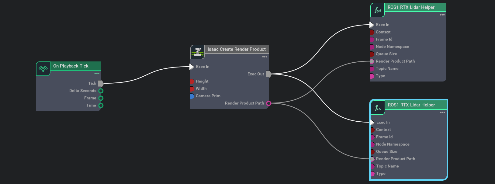
Connect the ROS bridge with the sensor output via Omnigraph Nodes. Open a visual scripting editor by going to Window -> Visual Scripting -> Action Graph. Add the following nodes to this graph:
On Playback Tick: This is the node responsible for triggering all the other nodes once Play is pressed.
Isaac Create Render Product: In the input camera target prim select the RTX Lidar created in step 2.
ROS1 RTX Lidar Helper: This node will handle publishing of the laser scan message from the rtx lidar. The input render product is obtained from the output of Isaac Create Render Product in step b.
To also publish point cloud data, add another ROS1 RTX Lidar Helper node. Under input type select
point_cloudand change the topic name topoint_cloud. This node handles publishing the point cloud from the RTX Lidar. The input render product is obtained from the output of the Isaac Create Render Product node from step b.
Once the graph has been set correctly, hit Play to begin simulation. The RTX Lidar should be sending the LaserScan and PointCloud2 messages and can be visualized in RViZ.
For RViZ visualization:
Run RViZ (
rosrun rviz rviz) in a sourced terminal.The fixed frame name in Isaac Sim for the RTX Lidar is set to sim_lidar, update the Rviz side accordingly.
Add LaserScan visualization and set topic to /scan
Add PointCloud2 visualization and set topic to /point_cloud

Running The Example
In one terminal source your ROS workspace and run roscore
In a new terminal with your ROS environment sourced, run
rviz -d <noetic_ws>/src/isaac_tutorials/rviz/rtx_lidar.rvizto start rviz and show the Lidar point cloudFinally, run the sample script
./python.sh standalone_examples/api/omni.isaac.ros_bridge/rtx_lidar.py
After the scene finishes loading, verify that you see the point cloud for the rotating Lidar sensor being simulated.
RTX Lidar Script sample
While most of the sample code is fairly generic, there are a few specific pieces needed to create and simulate the sensor.
We first need to create the RTX Lidar Sensor
_, sensor = omni.kit.commands.execute(
    "IsaacSensorCreateRtxLidar",
    path="/sensor",
    parent=None,
    config="Example_Rotary",
    translation=(0, 0, 1.0),
    orientation=Gf.Quatd(1.0, 0.0, 0.0, 0.0),
)
Here Example_Rotary defines the configuration for the Lidar sensor. Two generic configuration files (in addition to manufacturer/model-specific configurations) are provided in extsbuild/omni.sensors.nv.common/data/lidar/: Example_Rotary.json and Example_Solid_State.json.
To switch the Lidar to the example solid state configuration replace config="Example_Rotary", with config="Example_Solid_State".
Next, we need create a render product and attach this sensor to it
hydra_texture = rep.create.render_product(sensor.GetPath(), [1, 1], name="Isaac")
We can then create the post process pipeline that takes the rendered RTX Lidar data and publishes it to ROS:
writer = rep.writers.get("RtxLidar" + "ROS1PublishPointCloud")
writer.initialize(topicName="point_cloud", frameId="sim_lidar")
writer.attach([hydra_texture])
Note
You can specify an optional attributes={…} dictionary when calling activate_node_template to set node specific parameters. See the API Documentation for complete usage information.
Summary
This tutorial covered creating and using the RTX Lidar Sensor with ROS.
Adding an RTX Lidar sensor.
Adding an RTX Lidar and PointCloud ROS2 nodes.
Next Steps
Continue on to the next tutorial in our ROS Tutorials series, Add Noise to Camera.
Further Learning
Explore the inner workings of RTX Lidar sensors by learning How They work, the RTX Lidar Nodes that use them, and how to get RTX Lidar Synthetic Data.