7.1.9. Multiple Robot ROS Navigation
7.1.9.1. Learning Objectives
In this ROS sample, we are demonstrating Omniverse Isaac Sim integrated with the ROS Navigation stack to perform simultaneous multiple robot navigation.
7.1.9.2. Getting Started
Prerequisite
The ROS Navigation stack is required to run this sample. Install the ROS Navigation stack:
sudo apt-get install ros-$ROS_DISTRO-navigation
This tutorial requires
carter_2dnav,carter_description, andisaac_ros_navigation_goal. The packages are located under the directory<noetic_ws>/src/navigation/. They contain the required launch file, navigation parameters, and robot model. Complete ROS & ROS 2 Installation, make sure ROS environment is setup correctly and those packages are inside yourROS_PACKAGE_PATH.Completed ROS Navigation tutorial for a single robot.
ROS bridge is enabled and
roscoreis running before running Omniverse Isaac Sim.
7.1.9.2.1. Hospital Environment Setup:
In this scenario, an occupancy map is required. For this sample, we are generating the map of both the Hospital and Office environments using the Occupancy Map Generator extension within Omniverse Isaac Sim.
In a new stage, go to Create -> Isaac -> Environments -> Hospital.
At the upper left corner of the viewport, click on Perspective. Select Top from the dropdown menu. Select the Hospital prim and press F to zoom to selection. Adjust the camera view as needed.
Next, go to Isaac Utils -> Occupancy Map.
In the Occupancy Map extension, ensure the Origin is set to
X: 0.0, Y: 0.0, Z: 0.0. For the lower bound, setZ: 0.1. For the Upper Bound, setZ: 0.62. Keep in mind, the upper bound Z distance has been set to 0.62 meters to match the vertical distance of the lidar onboard Carter with respect to the ground.Select the Hospital prim in the stage. In the Occupancy Map extension, click on
BOUND SELECTION. The bounds of the occupancy map should be updated to incorporate the selected Hospital prim.The map parameters should now look similar to the following image:

A perimeter will be generated and it should resemble this image (Top View):

7.1.9.2.2. Office Environment Setup:
In a new stage, go to Create -> Isaac -> Environments -> Office.
At the upper left corner of the viewport, click on Perspective. Select Top from the dropdown menu. Select the Office prim and press F to zoom to selection. Adjust the camera view as needed.
Next, go to Isaac Utils -> Occupancy Map. In the Occupancy Map extension, set the map parameters to be similar to the following image:

Keep in mind, the upper bound Z distance has been set to 0.62 meters to match the vertical distance of the lidar onboard Carter with respect to the ground.
A perimeter will be generated and it should resemble this image (Top View):

Once the setup for either environments is complete, click on
CALCULATEfollowed byVISUALIZE IMAGE. A Visualization popup will appear.For Rotate Image, select 180 degrees and for Coordinate Type select
ROS Occupancy Map Parameters File (YAML). ClickRE-GENERATE IMAGE. Occupancy map parameters formatted to YAML will appear in the field below. Change the image name to your preference. Copy the full text.Create a YAML file for the occupancy map parameters called
carter_hospital_navigation.yamland place it in the map directory which is located in the samplecarter_2dnavROS package (carter_2dnav/map/carter_hospital_navigation.yaml).Insert the previously copied text in the
carter_hospital_navigation.yamlfile.
Note
For the office environment, follow the previous steps however create a YAML file called carter_office_navigation.yaml instead.
Back in the visualization tab in Omniverse Isaac Sim, click
Save Image. Set the same image name as in the map parameters and choose to save in the same directory as the map parameters file.The final saved image of the Hospital environment will look like the following:

The final saved image of the Office environment will look like the following:

An occupancy map is now ready to be used with Multiple Robot ROS Navigation!
7.1.9.4. Running Multiple Robot ROS Navigation
Load scenario:
For the hospital environment, go to Isaac Examples -> ROS -> Multi Robot Navigation -> Hospital Scene.
For the Office scenario, go to Isaac Examples -> ROS -> Multi Robot Navigation -> Office Scene.
Click on
Playto begin simulation.In a new terminal, run the ROS launch file and set the env_name parameter to either hospital or office to begin Multiple Robot Navigation with the desired environment.
roslaunch carter_2dnav multiple_robot_carter_navigation.launch env_name:=hospitalOR
roslaunch carter_2dnav multiple_robot_carter_navigation.launch env_name:=officeRViz will open and begin loading urdf models of three NVIDIA Carter robots, the global occupancy map, as well as the local costmaps of each robot.
To verify that all of the transforms are broadcasting, run the following command in a new terminal to visualize the ROS TF frame tree:
rosrun rqt_tf_tree rqt_tf_tree
The generated graph should look similar to the one shown below.
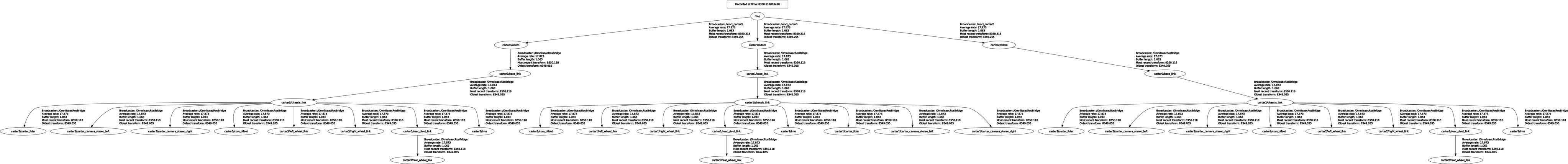
Since the positions of each robot is defined in multiple_robot_carter_navigation.launch, the robots should already be properly localized.
In RViz, click on Tool Properties -> 2D Nav Goal -> Topic, and set the topic namespace to either
/carter1,/carter2or/carter3corresponding to specific robot you wish to set the navigation goal for.Next, click on the
2D Nav Goalbutton and then click and drag at the desired location point in the map. The ROS Navigation stack will now generate a trajectory and the specified robot will start moving towards its destination! Repeat this process for every other robot.
Note
The ROS Image publishers are disabled by default to improve performance. To start publishing images, open the ROS_Cameras graph found under each of the Carter_ROS prims and enable the branch nodes as desired. To learn more see Carter_ROS OmniGraph Nodes.
7.1.9.4.1. Running in python directly
Alternatively, to load this sample environment from python directly, follow the steps outlined here.
7.1.9.5. Sending Goals Programmatically for Multiple Robots
The isaac_ros_navigation_goal ROS package can be used to set goal poses for multiple robots simultaneously. Refer to Sending Goals Programmatically to learn about the configurations and parameters of this package.
To send navigation goals to multiple robots simultaneously, setting up ROS namespaces are required. In a launch file, we can easily setup namespaces by wrapping the required params and node with the <group> tag. Refer to this page to learn more about the group tag.
Set up the namespace “carter1” by adding group tags around the parameters and node defined in
isaac_ros_navigation_goal/launch/isaac_ros_navigation_goal.launch. The resulting launch file should resemble the following:<launch> <group ns="carter1"> <param name="map_yaml_path" value="<PATH_TO_MAP_YAML>" /> <param name="iteration_count" type="int" value="3" /> <param name="goal_generator_type" type="str" value="RandomGoalGenerator" /> <param name="action_server_name" type="str" value="move_base" /> <param name="obstacle_search_distance_in_meters" type="double" value="0.2" /> <param name="goal_text_file_path" value="<PATH_TO_GOAL_TEXT_FILE>" /> <rosparam param="initial_pose">[0, 0, 0, 0, 0, 1, 0] </rosparam> <node name="set_navigation_goal" pkg="isaac_ros_navigation_goal" type="set_goal.py" output="screen"/> </group> </launch>
Remember to update the map yaml file path and the initial pose of carter1 for either the hospital or office scenario.
Note
If goal generator type is set to
RandomGoalGeneratorthen a goal text file will not be used.Duplicate the carter1 group configuration and modify them for carter2 and carter3 namespaces. The map yaml file path can be identical in all three groups. Make sure to update the initial poses of carter2 and carter3.
Note
If goal generator type is set to
GoalReaderthen a separate goal text file must be created for each namespace group.To run the newly modified launch file, use the following command:
roslaunch isaac_ros_navigation_goal isaac_ros_navigation_goal.launch
Note
Due to the higher complexity of the hospital or office scenes it may take up to 5 minutes for initial goals to be automatically set.
7.1.9.6. Summary
In this tutorial, we covered running multiple robots with the ROS navigation stack.
7.1.9.6.1. Next Steps
Go to the next tutorial Joint Control: Extension Python Scripting to learn how to move a manipulator using direct joint control.
7.1.9.6.2. Further Learning
To learn more about ROS Navigation refer to the ROS website: http://wiki.ros.org/navigation
ROS name conventions refer to the website: http://wiki.ros.org/Names.
Standalone python scripting version: Multiple Robot ROS Navigation. With this approach you have the ability to manually control the timestep and rate at which ROS components are published.