Walkthrough - Script and Graph Editor#
This file contains an example walkthrough for creating a node type definition using an AutoNode definition in the Script Editor and then constructing a graph containing a node of that type using the visual scripting Graph Editor. For other walkthrough tutorials see Walkthroughs.
This walkthrough will assume that the following extensions have been installed and are enabled in your application:
omni.graph for the core AutoNode functionality
omni.graph.ui for the OmniGraph fields in the Property Panel
omni.graph.window.generic for the visual scripting Graph Editor
omni.kit.window.script_editor for the Python Script Editor
Step 1: Open The Script Editor#
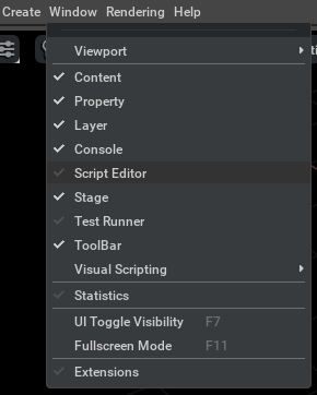
Even though you will be creating nodes through the GUI you still need to program your node type definition. The easiest way to do this is directly through the script editor, which you can access through the Window menu.
Step 2: Write The Script#
To start with you’ll need these basic imports to access the key AutoNode functionality, as well as numpy for the computation function.
# begin-step1
import numpy as np
import omni.graph.core as og
Then you can create your AutoNode definition, in this case to compute the dot product of two vectors:
Returns the fully qualified name of the new node type for easier use.
"""

@og.create_node_type
You can type directly or copy-paste into the script editor. When you’re done it should look like this:
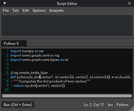
Hitting CTL-ENTER will execute the code and define your node type.
Step 3: Create A Graph#
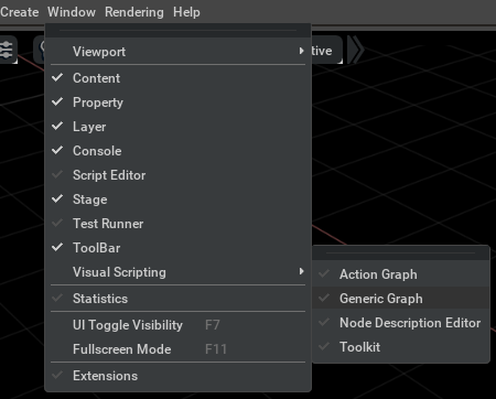
Now we will create a node of the new type by opening up the graph editor. For this example a simple push graph will do. Open up the Generic Graph editor first:
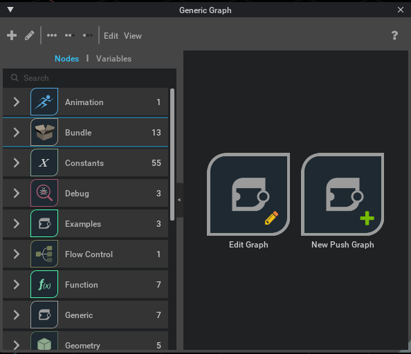
Then in the editor hit the New Push Graph option to create a graph.
Step 4: Instantiate New Node Type#
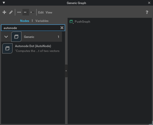
Now that you have a graph you can use the search bar for node types on the left to look for your newly created type. Use the search text “autonode” to zero in on the node type of interest.
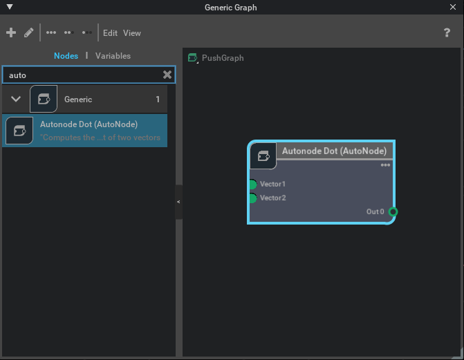
Now you can drag the node type definition onto the graph pane to instantiate a node of your new type. Notice that the names of the inputs correspond to the function arguments and the outputs are numbered, as per the description of the AutoNode function definition.
Step 5: Set Input Values#
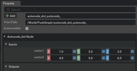
When you click on the node the property panel will open up to that node’s information. In particular you will have access to the inputs:vector1 and inputs:vector2 inputs, where you can type in some numbers. Enter the values 1.0, 2.0, 3.0 into inputs:vector1 and the values 4.0, 5.0, 6.0 into inputs:vector2.
Step 6: Check The Output#
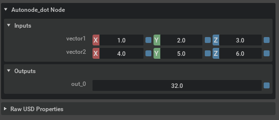
Below the inputs in the property panel you can see the output, where you’ll notice now contains the result of the dot product calculation. Everything works as with standard node type definitions and you are free to continue using this node type in your scene!
Warning
Although you can instantiate this node type any number of times in your scene you should be aware that saving a file with such node types will not work across sessions. In a normal workflow the extension will automatically register the node types it contains but that is not true with AutoNode definitions. To use them in a scene you have loaded you must import and execute the script that defines the node type.