5.2. Export URDF
5.2.1. Learning Objectives
This tutorial shows how to export a URDF file from usd in Omniverse Isaac Sim. After this tutorial, you will be able to convert robot USD files to URDF files using Omniverse Isaac Sim.
10-20 Minute Tutorial
5.2.2. Getting Started
Prerequisites
Review the Introductory Tutorial Series prior to beginning this tutorial.
5.2.3. Exporting A Robot
Let’s walk through the steps convert robot USD file to a URDF file. As well as talk about some advanced options.
5.2.3.1. The Basics
Let’s begin by first enabling the exporter extension.
Navigate to Windows -> Extensions and type urdf in the search bar, then enable the USD to URDF exporter extension.
This will add the USD to URDF Exporter menu option at the top of the app. Select it to open the extension, you will see the user interface as shown in the image below.
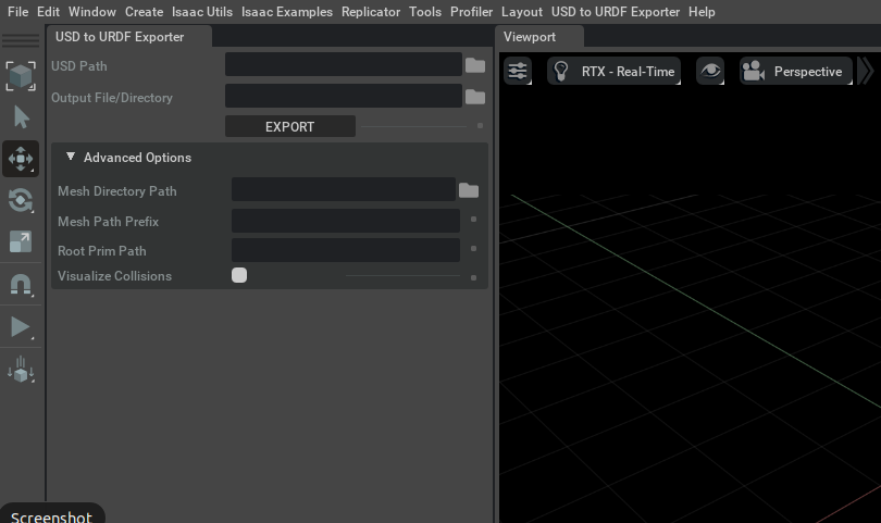
From here we can either directly export from a USD file, or export from the current stage.
This is done by either specifying a path to a USD file in the USD Path field, or by leaving the field blank.
For this tutorial, we will use the current stage, thus we will leave the USD Path field blank.
Open the USD for the Franka robot, which is found in the isaac asset root path at
Isaac/Robots/Franka/franka.usd.
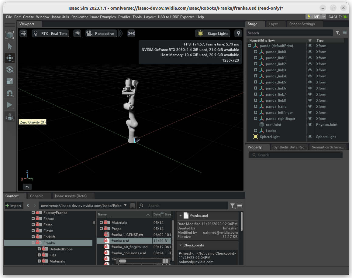
After the USD finishes loading, we just need to specify where we want the URDF filed to be saved.
Click on the folder icon for the Output File/Directory field to select where you want the result from the exported to be saved.
Select a desired output directory.
Your Output File/Directory should look something like this /home/<username>/franka/.
Click the EXPORT button, to export the robot with the panda prim (the default prim) as the root joint in the URDF.
The button will turn green while the export is processing, which may take several seconds.
When it turns back to gray, the process is done.
Open the output folder to view the resulting files.
You will see a franka.urdf file and a meshes directory.
To check the results, the URDF can be imported back to USD and opened in Isaac Sim. See the Import URDF tutorial for the steps to do that.
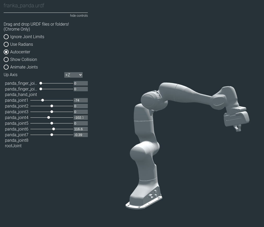
Alternatively, you can quickly view the results with this URDF Viewer Example website. Drag the output directory directly into the site to view the URDF file, and examine the joints.
5.2.3.2. Mesh File Paths
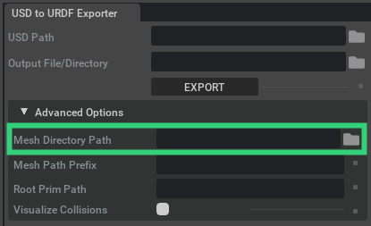
The directory for where the mesh .obj files are saved defaults to the name meshes, and is placed in the same directory as where the URDF file is saved.
You can specify an explicit directory by defining the directory path in the Mesh Directory Path field.
By default the paths to the mesh files are relative paths, which you can see by opening up the exported franka.urdf file in a text editor.
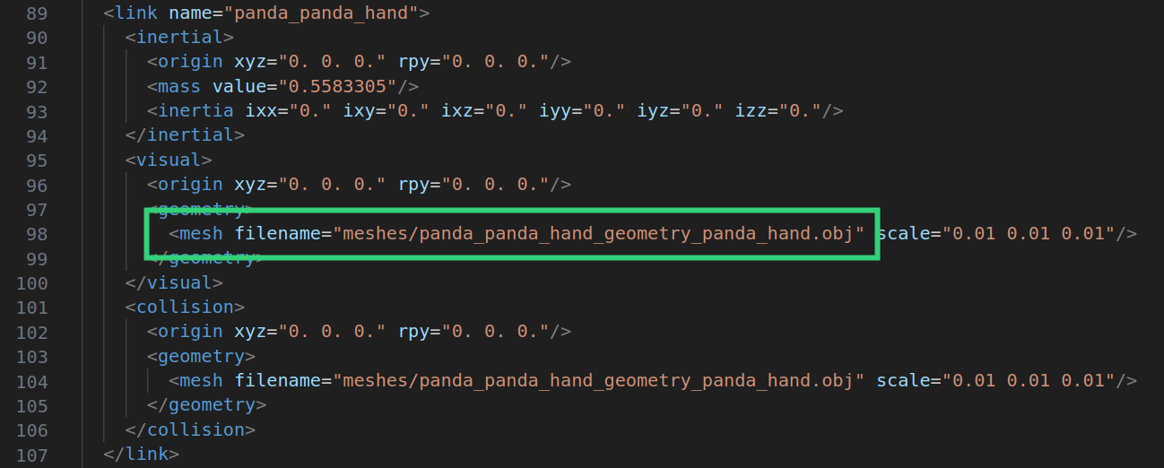
But often it is necessary to use absolute paths or a URI, which is necessary when using the URDF with ROS.
Any prefix can be prepended to the mesh file paths by specifying the prefix in the Mesh Path Prefix field.
For example, to make the Franka URDF loadable in RViz let’s turn the paths into a valid URI with the file scheme (i.e. file://).
To do this we will set the Mesh Path Prefix to file://<absolute path to output directory>/.
You can get the absolute path to the output directory by copying the text that is in the Output File/Directory field.
Your Mesh Path Prefix field should look something like this: file:///home/<username>/franka/.
Note
Note the three forward slashes at the beginning, and the trailing forward slash at the end.
After exporting you will now see that the mesh file paths in the URDF are all begin with the prefix.
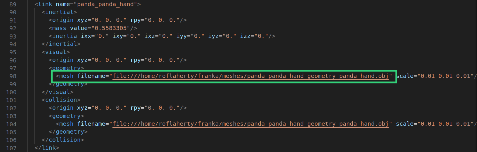
This allows for the URDF to be viewed in RViz.
5.2.3.3. Collision Objects
In a URDF file, a link often has two separate meshes associated with it: a visual mesh and a collision mesh.
In USD there is no distinction between a visual mesh and a collision mesh.
USD prims can have the PhysicsCollisionAPI attached to them, which tells the physics engine to resolve the motion of the body as it touches other bodies.
Additionally, prims can be set to be visible or invisible.
The USD to URDF exporter creates visual meshes and collision meshes for each link based on if it has the PhysicsCollisionAPI applied to it and if it is visible.
To explore how geometry prims map to visual and collision meshes in the URDF, let’s add a geometry prim to the Franka robot and export it in different ways to see what is created with each of the resulting URDF files.
Start by opening the USD for the Franka robot again (found at Isaac/Robots/Franka/franka.usd).
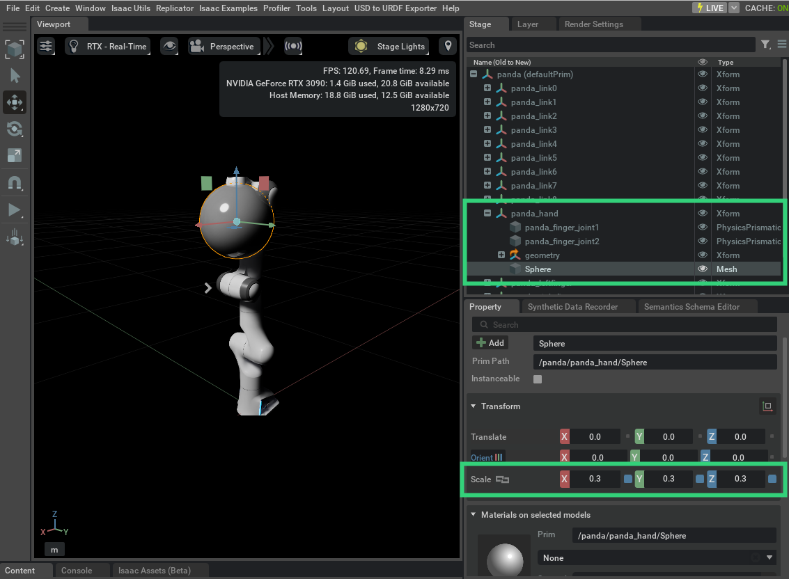
Right click the panda_hand Xform prim, and from the contextual menu select Create -> Mesh -> Sphere.
Then select the new Sphere Mesh prim, and change the scaling for the x, y, and z components to all be 0.3.
Your Franka should look like this.
Now export your current stage by following the steps discussed above and outlined below (note there is no need to even save your changes).
Open the USD to URDF Exporter menu
Select an output directory
Hit the
EXPORTbutton
Drag your output directory into the URDF Viewer Example website to view the results. You should see something like this.
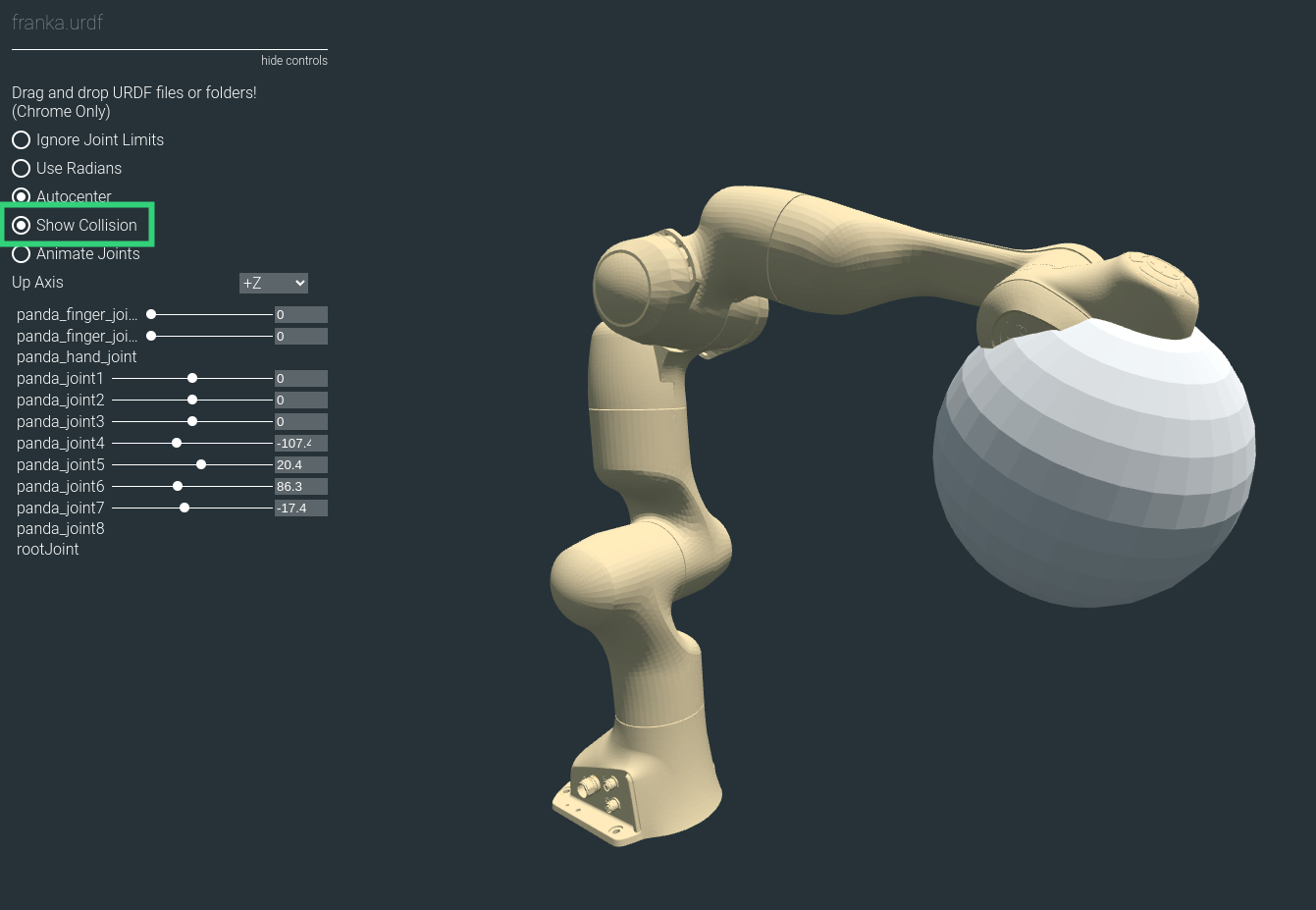
Make sure to enable the Show Collision option, which visualizes all the collisions meshes and highlights them with a gold color.
Notice how the sphere is not highlighted with the gold color, that is because in the URDF it is not a collision mesh, but is a visual mesh.
Next, back in the Franka USD, add the collision API to the sphere.
This can be done by selecting the Sphere prim and clicking the +Add button in the prim’s property menu.
Then select Physics -> Colliders Preset.
After adding the collision API to the sphere, re-export the USD stage to URDF and drag the output directory into the URDF viewer again (note you may need to refresh the viewer’s webpage before dragging in the new URDF).
You should see something like this.
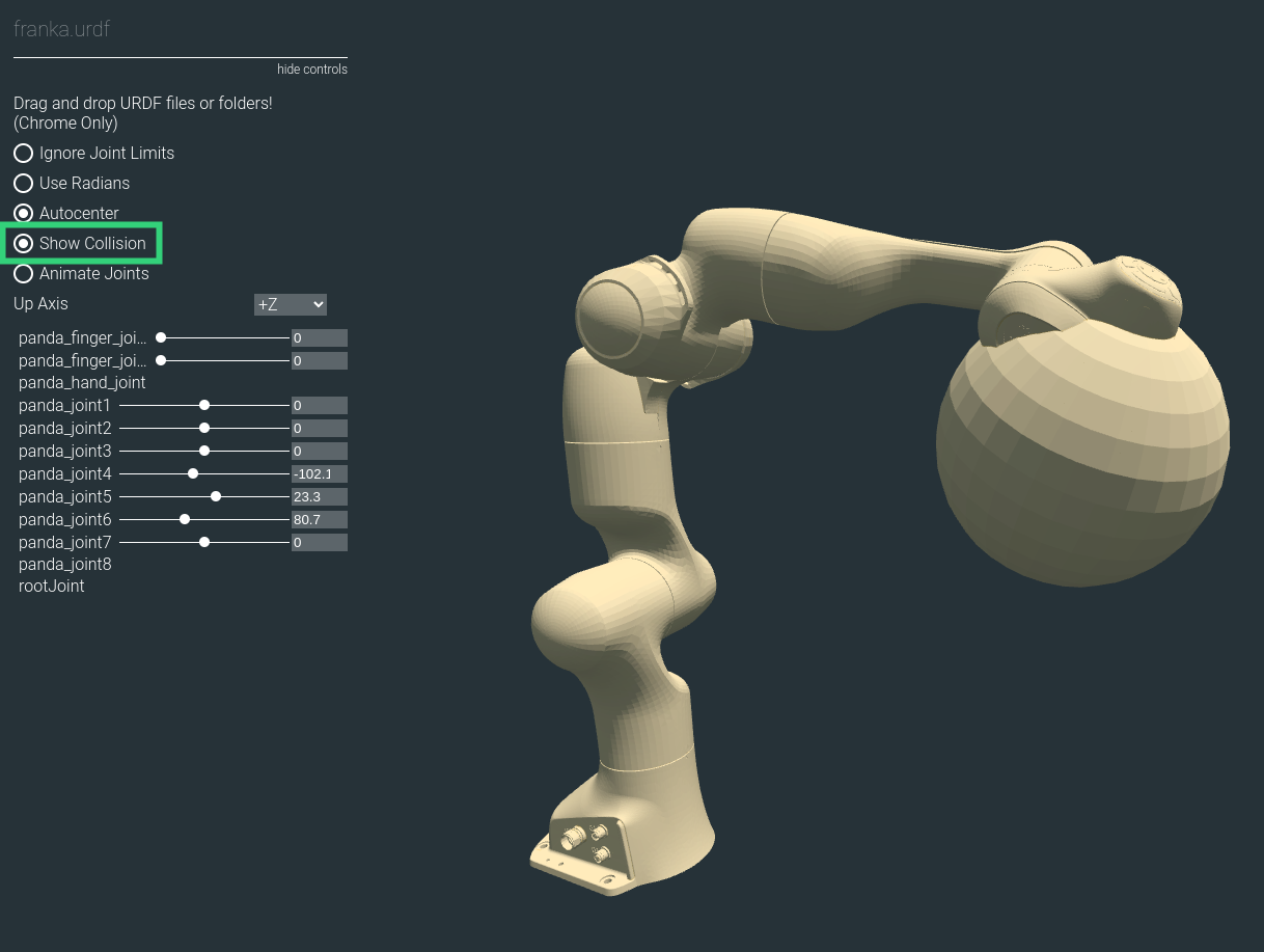
Again, make sure to enable the Show Collision option.
Notice that this time the sphere is highlighted with the gold color.
That is because the sphere is both a collision mesh and a visual mesh in the URDF file.
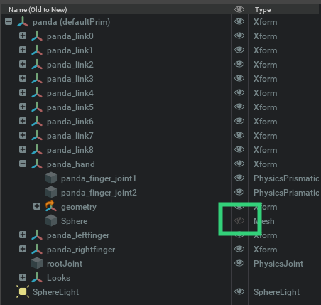
Finally, back in the Franka USD, make the sphere invisible by disabling the “eye” icon next to the Sphere prim.
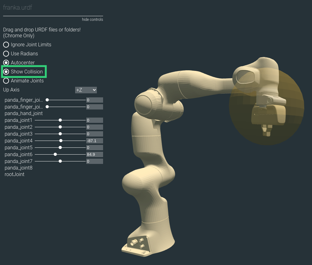
After making the sphere invisible, re-export the USD stage to URDF and drag the output directory into the URDF viewer again.
Initially you will not see the sphere, but after enabling the Show Collision, you will see the sphere highlighted with the gold color.
This is because the sphere is a collision mesh but not a visual mesh in the URDF file.
You should see something like this.
Thus, to export link collision meshes correctly to URDF, they should have the collision API and should be set to invisible.
To make all collision API prims into visual meshes, regardless of the visibility state of the prim, enable the Visualize Collisions option under the advanced options of the USD to URDF Exporter.
5.2.4. Limitations
The USD format offers much greater expressiveness and provides more capabilities compared to URDF. The set of all scenes and robots that can be described using USD is a superset to those that can be described with URDF. Meaning all scenes and robots that can be described by a URDF file can also be described by a USD file, but not vice versa. Therefore, there is no direct one-to-one mapping between USDs and URDFs. Consequently, when converting a USD file to a URDF file, several assumptions are made and constraints are imposed.
Here is list of constraints for the USD in order for the USD to URDF exporter to succeed.
The kinematic structure of the robot must be a tree structure
Scaling on sphere shapes must be the same for every axis
Scaling on cylinder shapes must be the same for radius axes (i.e. the non-height axes)
The coordinates for each body frame of a joint must be co-located and aligned
Parent link prims should be
Body 0, and child link prims should beBody 1of the jointJoint prims must be either
prismatic,revolute, orfixedLink prims must be
Xform.Sensor prims must be either
CameraorIsaacImuSensorGeometry prims must be either
Cube,Sphere,Cylinder, orMeshGeometry prims must be “leafs” in the kinematic tree
If your USD violates one of these constraints and error will be thrown.
5.2.5. Summary
This tutorial covered the following topics:
Exporting URDF files using the exporter GUI
Validating the URDF result by viewing in a viewer
Understanding how collision and visual meshes in the URDF are controlled from the USD
Outline the limitation of the USD to URDF exporter
5.2.5.1. Further Learning
Checkout USD to URDF Exporter to learn more about other configuration options.