Rigging a Robot (REFACTOR)
Danger
THIS SECTION NEEDS TO BE REFACTORED
With the exception of using the URDF Importer, most robots imported using CAD or other 3DCG software may not contain joint information. This is a step-by-step instruction on how to rig a robot, and turn static parts into an articulated, controllable robot.
From CAD Imports
Prepare CAD Assemblies
Exporting your assembly in a default position where parts are aligned at the joints, and assembly are symmetrical and aligned with a reference frame will make the rigging much easier.
Label Rigid Body Parts
Articulation can only be calculated on rigid bodies, so the first step is to make the relevant parts of the robot rigid bodies. Not every single piece of the assembly needs to be a rigid body, skipping parts such as bolts and nuts can significantly lighten the physics simulation load.
Select the Xform corresponding to the part, and under PhysX Properties tab, go to Add Prim Component and click on PhysicsAPI. Repeat for each part.

Add Joints
Select parts. Ctrl-Shift and click to multi-select the Xforms that will be connected by the joint. The first one you select is the child (body1), the second one is the parent (body0).
Select joint type. Physics -> Joint Attributes-> Type -> Revolute/Prismatic/etc.
Add joint. Physics -> Add -> Joint -> Between Selected. A joint will now appear under the parent Xform. You can move it out of the parent’s branch if desired. You can always find the relevant information regarding the joint under PhysX Properties -> Physics Joint.
Place the joint. The joint is by default placed at the origin of the parent part. In most cases, this is not where the joint is. We will manually type in the joint location in reference to one of the rigid bodies involved. You may use body0 as the reference, or body1.
In the video above, you will see that the joint is placed by offsetting it from the parent body (localPos0) in the y and z directions.
In the video below, you can see that the same joint can be placed by using the child as the reference frame. First you can find the center of the child’s rigid body by making localPos1 to be zeros, and localRot1 to be all zeros except for one of the terms, which should be 1. Then you can type in the joint offset from the origin from there.
You can also directly drag the joint using the gizmo in the viewport, although that will likely to be very inaccurate.
Note
The origin of each mesh is automatically placed at the center of mass (COM) when imported using the STEP importer. For asymmetrical parts, this will not be the center of the part. Make sure the joint position offset is the offset from the COM, and not the origin of the part in your CAD or mesh file.
Add Articulations
Articulations are an advanced, hierarchic mode of joints, optimized for mechanism and the objects that are connect in a tree structure. It is faster and more stable to calculate the joints on a robot when they are turned into a chain of articulations.
To turn the joints into articulations:
Add ArticulationAPI to the main robot Prim. Select the main robot Prim on the Stage Tree, and go to PhysX Properties->Add Prim Component and select ArticulationAPI. If your robot is suppose to be stationary, check the fixBase box.
Establish the root of the articulation, or the start of the kinematic chain, such as the base of a manipulator, or the chassis of a vehicle. Find the Prim that represents this root link on the Stage Tree, then go to the menu Physics -> Add -> Joint -> To World Space. A joint will appear under the root Prim. You can rename it and even move it out of the root Prim and into the main robot Prim.
Remove the default joint type that was added to the root joint by going to PhysX Properties-> Remove Prim Component and select whatever joint type that appears under the dropdown menu. By selecting it, it is removed. You can check by opening the dropdown menu again, and it should be empty.
Add the ArticulationJoint to this root joint instead. Go to PhysX Properties->Add Joint Component, select ArticulationJoint. This enables the section under the PhysX Properties called Physics Articulation Joint. Select ArticulatedRootFixedBase for the dropdown menu “Articulation Joint Type”. If your robot is mobile and does not have a fixed base, select ArticulatedRoot instead.
For rest of the joints in the kinematic chain. Select the joint on the stage tree, and go togo to PhysX Properties->Add Joint Component and select ArticulationJoint
Robots with Closed Kinematic Chains
Currently, articulation features are only supporting tree-like kinematic chains, and will not work for closed-kinematic chains. Therefore, if your robot has a closed-kinematic chain, you will need to break it up by skipping one of the joints when defining the articulation chain. In this simple platform example, all the spherical joint connecting the legs to the top plate are not included in the articulation chain.
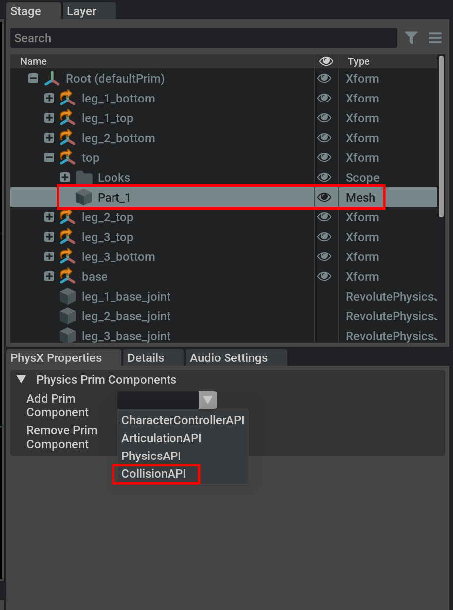
Add Collision
To add collision properties to a rigid body, select the Mesh that is associated with the body on the Stage Tree (as oppose to the Xform). Then go to PhysX Properties->Add Prim Component and add CollisionAPI.
Visualizing Collision Meshes
Not all the rigid bodies need to have collision properties, and collision meshes are often a simplified mesh comparing to the visual ones. Therefore you may want to visualize the collision mesh for inspection.
To visualize collision in any viewport:
Select: the
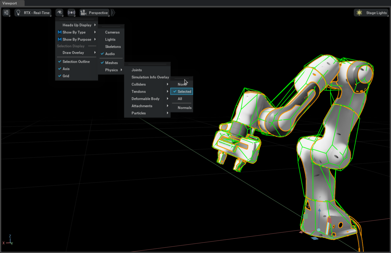 eye icon.
Select: Show by type.
Select: Physics.
Select: Colliders.
Check: All.
The visualization of collision meshes uses the PhysX Visual Debugger (PVD) plugin. You can find more information on PVD itself here.
Add Joint Drives
For joints that are actuated, we need to add joint drive properties to it. Select the desired joint on the Stage Tree, and go to PhysX Properties->Add Joint Component and add Drive. This enables the section “Joint Drive” under the “PhysX Properties” tab.
Currently, two types of drives are supported: position and velocity. For position drive, set a relative high stiffness comparing to the damping, and set a reasonable maxForce. For velocity drive, set only damping and set stiffness to 0.
You can test if the drive is active by start the simulation and manually change the drive target.
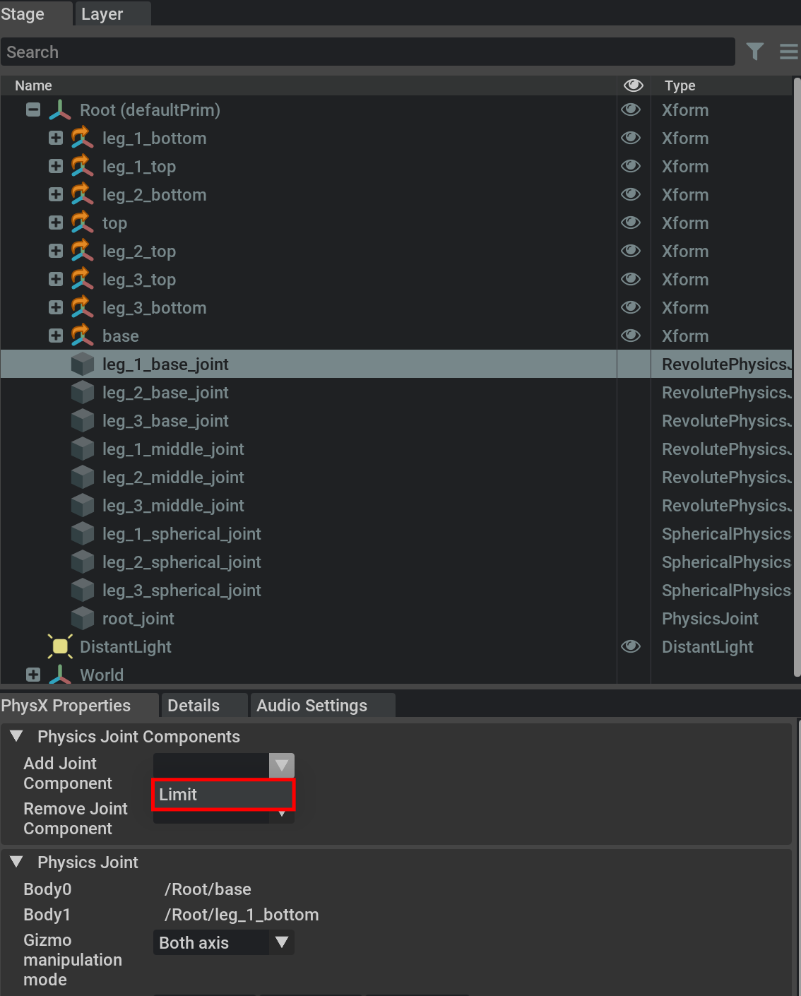
Joint Limits
You can add joint limits to each joint by going to PhysX Properties->Add Joint Component and add Limit. A new section called “Joint Limit” will appear under the PhysX Properties tab.
Rigging a Mobile Robot
The steps for rigging a mobile robot is very similar. The biggest difference being the robot’s base is not fixed. Here is a step-by-step tutorial in video.
Extending a Robot
If you have an existing rigged robot, it is possible to create alternate versions of the robot using the same base asset. For example, the UR10 base asset was loaded from the example ur10 urdf, which contains no end effector. And then two derived versions are shown, with a short surface gripper, and a longer surface gripper. Changes made in the base assets this way will impact all assets which contain it as reference.
Example
These are the steps to create an extended robot model:
Create a new empty scenario. If any world prim is created, delete it.
Locate the base robot in the contents path, and drag it onto the scene. at the position
(0,0,0). In the video example we are using the UR10 robot.
Set the Robot root as the default Prim by Right-clicking at the robot root and selecting
Set Default Prim.Create an XForm inside the end robot’s effector link and set its pose to
(0,0,0). In the example we will place it underwrist_3_link, and name the new Xformee_link.
Move the XForm outside of the end effector link and inside the robot link.
Make the new XForm instanceable.
Under the PhysX Properties tab, Add the
Physics APIPrim component.
Locate the End Effector Asset and drag it into the newly created Xform.
In the Physics menu, select
Physics->Joint Attributes->Fixed.
Select the robot link, and the newly created Xform, and on the Physics menu select
Physics->Add->Joint->Between Selected. This will create a fixed joint between the new robot’s end effector link and the newly created link.
Make any final changes to the asset, and save the file.
Import JetBot from CAD to USD
The Omniverse Isaac Sim package comes with a STEP version of the JetBot. To load it, go to Window->Isaac->Step Importer, select the Built-in Step Files, pick the JetBot. You can make changes to its tessellation quality and material shader properties.
Once all import changes are made to satisfaction, click on Finish Import, and select Save Flattened. This will save the entire jetbot as a single USD, making it easier to make further changes to its structure.
Creating the Camera Sensor
Let’s create the camera sensor now. First go to Create->Camera, and a camera will be created on /Root/Camera. To facilitate its positioning, place it inside the lens’ prim by dragging the camera into the lens’ mesh on the Stage window.
Note
To find which mesh is the Lens, you can click on the lens mesh in the viewport.
Notice on the details pane the Extent property, which shows the distance to the bounding box on every direction from the mesh center.since the lens forward axis is Y, the distance to the lens top is near 0.260cm in the Y direction.
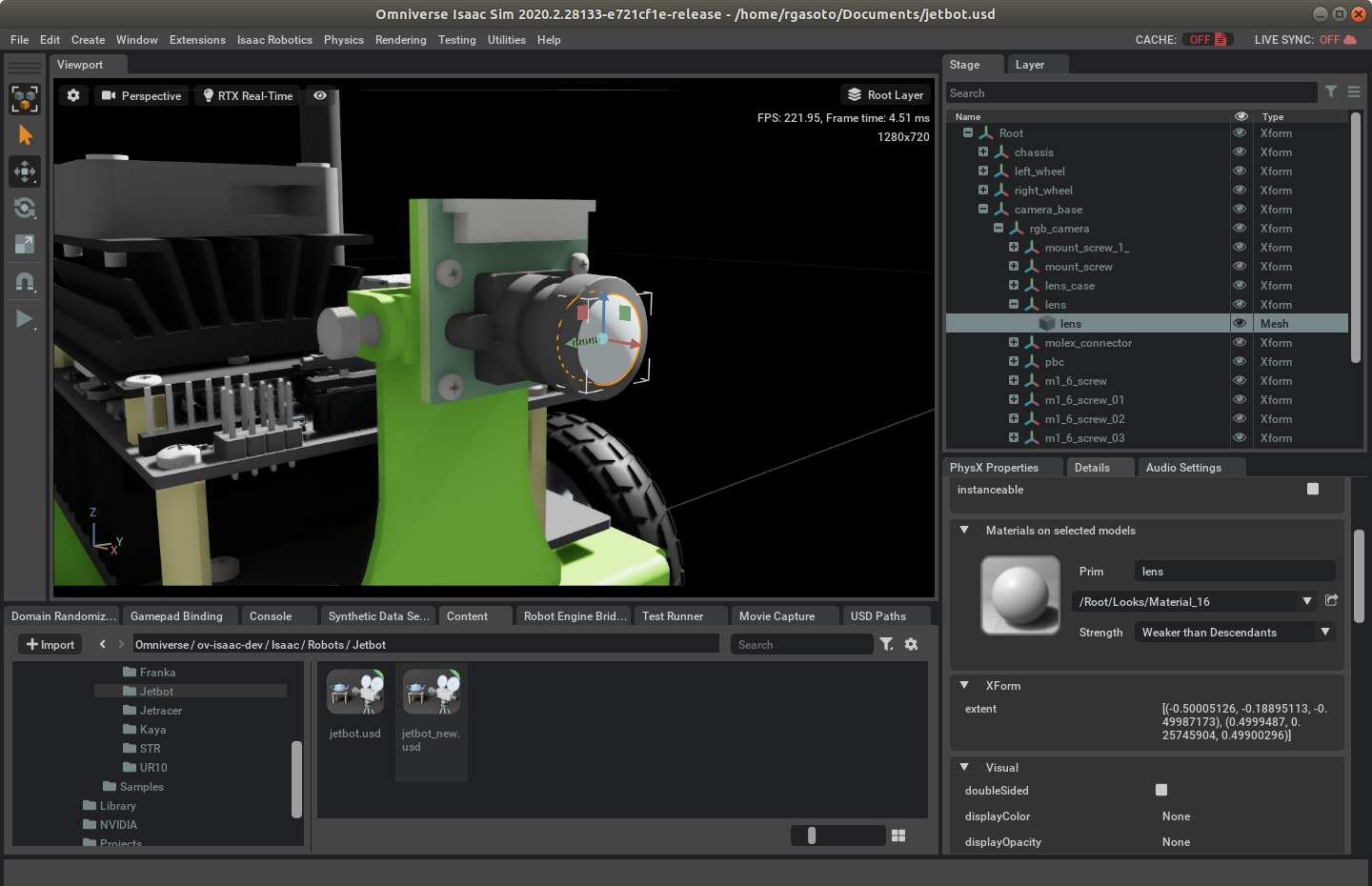
After dragging the camera inside the lens mesh, change its local transform to (0, 0.260, 0) so it sits right on the edge of the lens. To adjust the camera orientation, rotate it on the X axis by 90 degrees, and on the Z axis by 180 degrees.
Now, move the camera out of the lens mesh by dragging it back to /Root, and the camera path now should be /Root/Camera, but this will not be the final path, as there are more steps before we get the final asset.
Simplifying the Model
Having every individual components is good for setting up the robot, but once everything is settled, it makes sense to simplify the structure to be computationally more efficient. To do so, we use the mesh merging tool to consolidate meshes together as a single mesh.
This results in less transforms being reported at every timestep, reducing the computation time. The merge process will retain all material assignment so the robot will look the same.
We will create the following structure for the JetBot:
- Root
- Chassis
Body
Left Antenna
Right Antenna
Caster Ball Case (back and front)
Caster Ball (back and front)
Camera
Left Wheel
Right Wheel
The choice of breaking the chassis in multiple smaller components are due to two reasons: For the Camera component, it is due to its adjustable nature, so we can configure the position the camera is pointing to. For the other components, it is to achieve a middle ground between performance and precision on the collision shapes. Each subcomponent will be set up as a convex hull, so breaking it down by the most prominent features (such as the antennas), allows us to perform a significant performance increase over selecting Physx convex decomposition for the whole body.
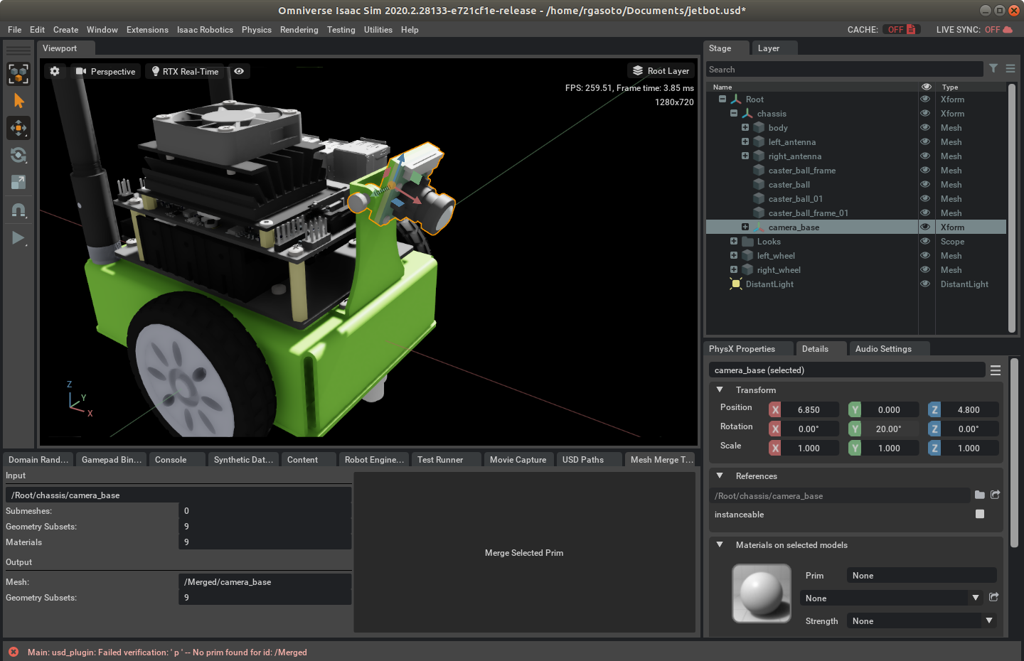
To create that structure, First drag /Root/chassis/electronics into /Root/chassis/body, and then move the /Root/chassis/body/caster_ball_assembly and /Root/chassis/body/caster_ball_assembly_1_ to /Root.
Now to merge all body components on a single mesh open menu Window->Isaac->Mesh Merge Tool, select /Root/chassis/body and click Merge Selected Prim. This will create a single mesh with GeomSubsets for each material it uses in /Merged/body. Delete all contents inside /Root/chassis, and reset its orientation to (0,0,0), then drag /Merged/body to /Root/chassis.
Repeat this process for the wheels, antennas and the camera shroud, but don’t delete the camera base prim. Instead, delete all its contents, and move the merged mesh into it, along with /Root/Camera. Move /Root/camera_base/ into /Root/chassis. You can now adjust the camera orientation by changing the rotation angle of the Y axis in the transform /Root/chassis/rgb_camera.
Move the caster case and ball meshes into the /Root/chassis, delete empty Xform Prims, and your asset will be ready for rigging physics.
To keep meshes organized, you may opt to create another base transform to keep all the chassis components inside. In the asset provided, we created the transform /Root/chassis/geometry for that purpose.
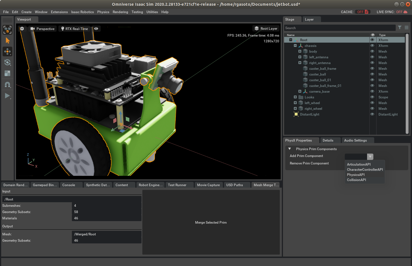
Setting up Physics
First, the robot will be set up as an articulated chain. Click on /Root, then open the Physx Properties tab, and add Articulation API under the Add Prim Component dropdown. Similarly, add PhysicsAPI and massAPI:mass to /Root/chassis, /Root/left_wheel and /Root/right_wheel. For each component inside Root/chassis and also for the wheels, add CollisionAPI. This will flag the simulation to treat those prims as physics-enabled rigid bodies, with a given mass. Set the Root/chassis mass to 1.0, and the wheels to 0.200.
For the Caster Balls and wheels, change the Collision Approximation to Bounding Sphere. This will ensure a single contact point will be cast with the ground during simulation, providing additional stability and performance.
Now let’s set up the joints between the chassis and the wheels.
First, set the root of the articulation to the chassis. Select /Root/chassis, and click on Physics->Add->Joint->To world space. The joint will be created on /Root/chassis/revolute_joint. Rename it to root_joint by double-clicking on the joint, editing the name and then click OK. On the Physx Properties tab, remove the RevoluteJoint component, and add ArticulationJoint. Scroll down and set the articulation type to articulatedRoot.
To connect the wheel to the chassis, select the /Root/chassis/left_wheel, and then also select /Root/chassis by pressing ctrl and clicking on it, and click on Physics->Add->Joint->between selected. Rename the joint to left_wheel_joint, and on the Physx Properties tab, add the ArticulatedJoint and Drive components. Change the joint localPos1 to (0, 0, 0) and localRot1 to (1, 0, 0, 0) to align it with the wheel axis. Change the joint drive type to velocity, and set the damping to 1e6.
Likewise, do the same for the right wheel, with the exception that localRot1 must be set to (0, 0, 0, 1).
We could add spherical joints for the caster balls, but having them with a low friction to the ground is an equivalent, faster simulation. To add a low friction material to the casters, click on Physics->Add->Physics material, rename it to caster_material, and set the dynamic and static friction to 0.00 on the details tab. Then, click on the caster balls and assign the caster ball material in the details tab under Physics materials section. Do the same for the left and right wheels for a wheel material with friction 1.0, and physics should be all set.
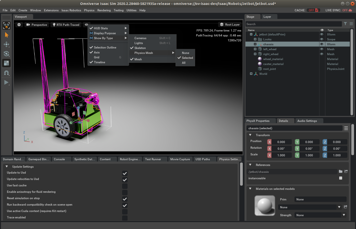
Note
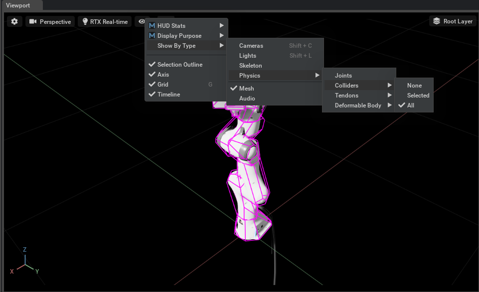
You can enable debug visualization of the collision meshes by clicking on the Show/Hide button (eye icon on the viewport)->Show by type->Physics Mesh->Selected or All
Testing JetBot
Finally, let’s make the final settings for the JetBot Asset. Ensure that /Root is set as default Prim. You can set it as the default prim by right-clicking on it in the stage editor tab, and selecting set as Default Prim.
then. click on Physics->Add->Physics Scene, and Physics->Add->Ground Plane, Drag the /Root/PhysicsScene and to /World. This is important because Everything that is under the default prim gets loaded on authored stages when the USD is referenced. Keeping the physics scene out of the default prim allows us to locally test the asset, while not interfering with it when loaded by other stages. Finally, copy Root/staticPlaneActor to /World and set its position to (0, 0, -3.360).
Now you can press the Play button and check if jetbot remains assembled. If it does, select the wheel joints and give them some target value to check if jetbot moves.
Note
If changing the joint target by the UI, remember to un-select the joint prim before stopping the simulation, as it may update the joint pose with incorrect transforms.