

Point Cloud Editing#
The Selection Box is an interactive 3D bounding-box tool. Use it to
spatially filter and operate on Point Cloud data in the viewport. It is part of
the omni.pointcloud.ui extension and loads automatically with the Point
Cloud Streaming Bundle extension.
Use the Selection Box to:
Visually define a region of interest within a streamed or imported Point Cloud to run clash detection queries.
Run spatial operators (Cut Inside, Cut Outside, Copy & Paste) on USD Points or streamed Point Clouds.
Snapshot the current box state as a hidden USD prim for comparison or reuse.
Selection Box Window Panels#
The Selection Box window contains five collapsible panels.
Selection Workflow describes how to use the Selection Box.
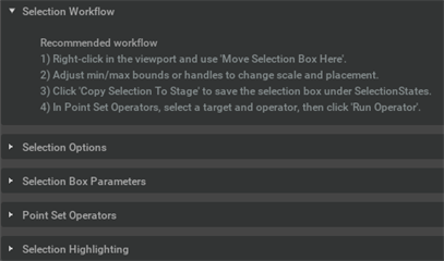
Selection Options — display and behavior toggles:
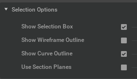
Show Selection Box — Toggles solid box prim visibility in the viewport (default: on).
Show Wireframe Outline — Toggles a viewport wireframe overlay on the selection box (default: off).
Show Curve Outline — Toggles the BasisCurves prim outline (default: on).
Use Section Planes — Clips everything outside the box.
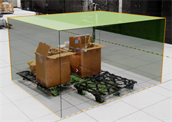
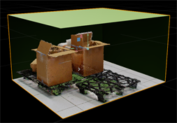
Selection Box Parameters — defines the spatial extent of the box:
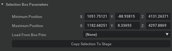
Minimum Position (X, Y, Z) — Lower bound of the axis-aligned bounding box (default: -1.0, -1.0, -1.0).
Maximum Position (X, Y, Z) — Upper bound of the axis-aligned bounding box (default: 1.0, 1.0, 1.0).
Note
The minimum and maximum position values update automatically so the minimum is always smaller than the maximum across all dimensions.
Load from Box Prim — Imports bounds from an existing box-type USD prim in the Stage.
Note
You can create box-type USD prims manually (for example, Create > Shape > Cube) for use with the Selection Box.
Copy Selection To Stage — Saves the current box to the Stage as a hidden snapshot under
<defaultPrim>/SelectionStateswith auto-incremented names (for example,SelectionToolBox01,SelectionToolBox02).
The following steps describe how to open the Selection Box and place it:
Open Tools > Selection Box.
Confirm the temporary
SelectionToolBoxprim (Cube type) andSelectionToolCurvesprim (BasisCurves) in the Stage.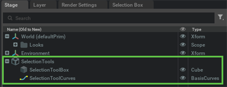
Confirm that the active viewport tool is Selection Box.
Note
By default, Selection Box edits are authored in the USD session layer (
useSessionLayer = true). They are not saved to the root layer unless you change this setting.Right-click a Point Cloud surface in the viewport where you want to place the box.
Select Place Selection Box from the context menu.
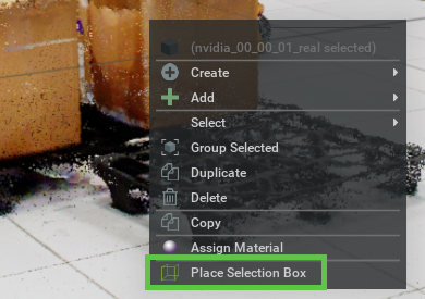
The Selection Box center moves to the indicated world position, and the box uses default dimensions.
Note
If no valid hit point is found (for example, when you right-click empty space), a warning toast notification appears and the box does not move.
Resize and save the box:
Use the viewport pivot to position and resize the box.
Select the
SelectionToolBoxprim in the Stage to use the standard viewport transform.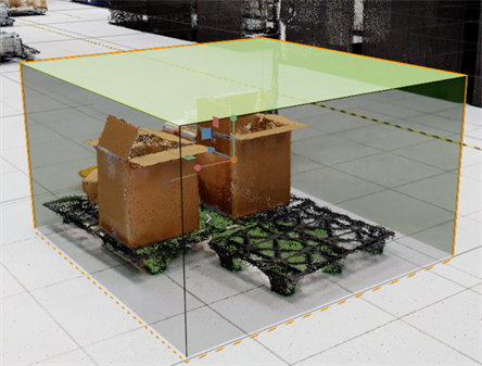
Note
The Minimum Position and Maximum Position fields in the Selection Box Parameters panel stay synchronized automatically.
To save the box permanently to the Stage, select Copy Selection To Stage. You can create multiple boxes with different dimensions and locations in the Stage.
Note
Until you select Copy Selection To Stage, the current box is temporary and is removed when you close the Selection Box window.
Point Set Operators — applies spatial operations scoped to the current box bounds:
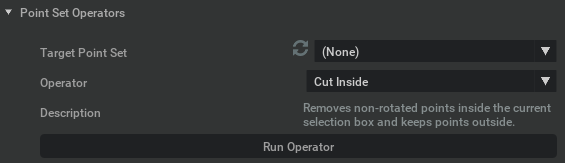
Source Geometry — Lists all compatible Point Cloud prims in the Stage (USD Points or NVSealedUsdArchive streamed point sets).
Operator — Available operators depend on the target prim type.
USD Points Type:
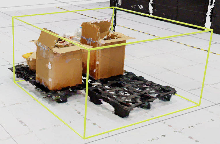
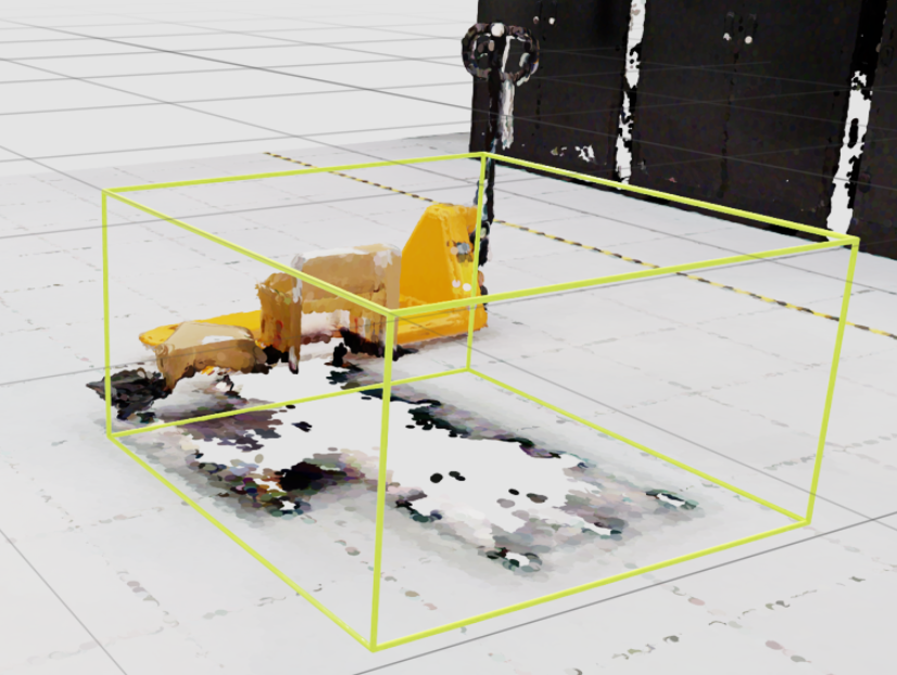
Cut Inside — Removes non-rotated points inside the current Selection Box and keeps points outside.
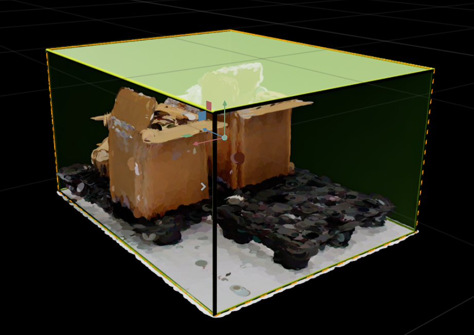
Cut Outside — Keeps non-rotated points inside the current Selection Box and removes points outside.
Merge Points — Merges sibling USD point sets under the same parent group into a single USD point set.
Copy & Paste — Copies non-rotated points inside the Selection Box into a new USD point set.
Pointset Info — Logs diagnostics about the selected USD points prim.
Meshing — Reconstructs a mesh from USD Points using the local GPU.
Streamed Points Type:
Streamed Points Copy & Paste — Extracts streamed points inside the Selection Box at the highest resolution and writes them as editable USD points.
Streamed Points Copy Nodes — Copies streamed nodes that intersect the Selection Box into a new streamed points prim at the highest resolution. This can include points outside the Selection Box.
Streamed Points LOD Box — Creates a streamed LOD Selection Box (exclusion) from the current selection bounds and a fresh
_crop_NNsibling that carries its own inclusion-mode box.Meshing — Reconstructs a mesh from streamed point clouds at the highest resolution using the local GPU.
Run Operator — Executes the selected operator. Result and timing are logged to the console. Potential errors are highlighted by a warning message.
Selection Highlighting — assigns and live-updates a highlight material on a point set:
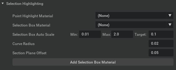
Point Highlight Material — Select a USD Points prim as the highlight target.
Selection Box Material — Select a compatible MDL material from the Stage (must expose
minPositionandmaxPositionparameters).Selection Box Auto Scale — Auto-scales the Selection Box curve outline based on camera distance on placement.
Curve Radius — Adjusts the width of the curve outline (default: 0.02).
Section Plane Offset — Outward distance (world units) between the box faces and the RTX section planes. This offset keeps the selection box and curve outlines from being clipped when Use Section Planes is on (default: 0.05).
Add Selection Box Material — Creates a transparent material in the Stage, binds it to the Selection Box, and places it under
<defaultPrim>/Looks.
Operator: Cut Inside#
The following steps describe how to use the Cut Inside operator:
Position the Selection Box around the area of interest.
In the Point Set Operators panel, select the target USD Points prim from the Source Geometry dropdown.
Select Cut Inside from the Operator dropdown.
Select Run Operator.
Points inside the Selection Box are removed from the target prim.
Operator: Cut Outside#
The Cut Outside operator keeps points inside the current Selection Box and removes points outside it from the target USD Points prim.
Position the Selection Box around the points you want to keep.
In the Point Set Operators panel, select the target USD Points prim from the Source Geometry dropdown.
Select Cut Outside from the Operator dropdown.
Select Run Operator.
The target prim contains only the points inside the Selection Box. As with Cut Inside, this operator is documented for non-rotated points.
Operator: Merge Points#
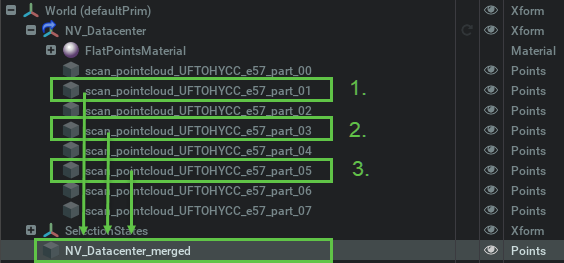
The Merge Points operator combines sibling USD point sets under the same parent group into a single USD point set.
In the Stage, identify the sibling USD Points prims under the parent group you want to merge.
In the Point Set Operators panel, select a USD Points prim in that group from the Source Geometry dropdown.
Select Merge Points from the Operator dropdown.
Select Run Operator.
Select Run Operator again for each additional sibling USD point set.
Inspect the resulting USD point set in the Stage and viewport.
The merge is based on the sibling point sets under the same parent group; it is not an extraction of points inside the Selection Box.
Operator: Copy and Paste#
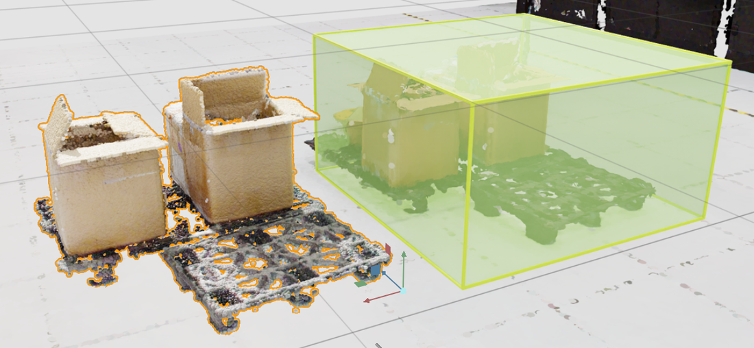
The Copy & Paste operator copies non-rotated points inside the Selection Box from a USD Points prim into a new USD point set.
Position the Selection Box around the points you want to copy.
In the Point Set Operators panel, select the source USD Points prim from the Source Geometry dropdown.
Select Copy & Paste from the Operator dropdown.
Select Run Operator.
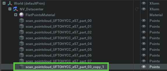
Locate the new USD Points prim in the Stage and inspect the copied subset.
Use Streamed Points Copy & Paste instead when the source is a streamed
point cloud (NVSealedUsdArchive).
Operator: Pointset Info#
The Pointset Info operator logs diagnostics about the selected USD Points prim to the console.
In the Point Set Operators panel, select the USD Points prim you want to inspect from the Source Geometry dropdown.
Select Pointset Info from the Operator dropdown.
Select Run Operator.
Review the diagnostics in the console.
Use this operator to inspect the selected point set. Its output is diagnostic information rather than a new point set or a cropped subset.
Operator: Streamed Points Copy and Paste#
The following steps describe how to use the Streamed Points Copy & Paste operator:
Position the Selection Box around the area of interest.
In the Point Set Operators panel, select the source streamed point cloud (
NVSealedUsdArchive) from the Source Geometry dropdown.Select Streamed Points Copy & Paste from the Operator dropdown.
Select Run Operator.
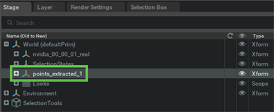
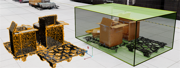
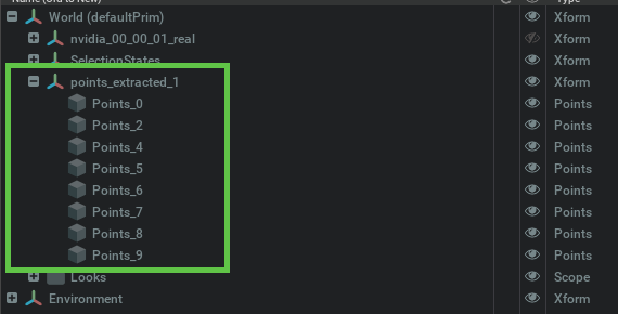
Locate the new USD Points prim in the Stage. Inspect, transform, or save it as a separate USD.
Operator: Streamed Points Copy Nodes#
The Streamed Points Copy Nodes operator copies streamed nodes that intersect the Selection Box into a new streamed points prim at the highest resolution.
Position the Selection Box around the region of interest.
In the Point Set Operators panel, select the source streamed point cloud (
NVSealedUsdArchive) from the Source Geometry dropdown.Select Streamed Points Copy Nodes from the Operator dropdown.
Select Run Operator.
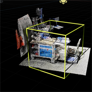
Locate the new streamed points prim in the Stage and inspect the result in the viewport.
Note
This operator copies intersecting nodes, so the result can include points outside the Selection Box. To extract only points inside the box as editable USD Points, use Streamed Points Copy & Paste.
Operator: Streamed Points LOD Box#
The following steps describe how to run the Streamed Points LOD Box operator:
Position the Selection Box around the region of interest that should be streamed within a different box.
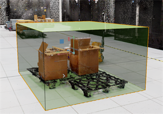
In the Point Set Operators panel, select the source streamed point cloud (
NVSealedUsdArchive) from the Source Geometry dropdown.Select Streamed Points LOD Box from the Operator dropdown.
Select Run Operator.
Inspect the result:
Close the Selection Box tab for better visibility in the viewport.
Locate the new prim with a
_crop_NNsuffix in the Stage.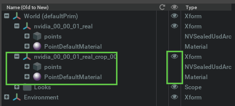
Confirm that the new prim contains the points excluded from the Point Cloud dataset.
Switch between the two prims using Hide and Show in the Stage. Edit, transform, or save the new prim as a separate USD.
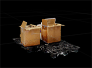
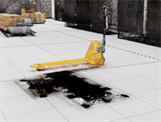
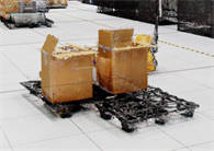
Operator: Meshing#
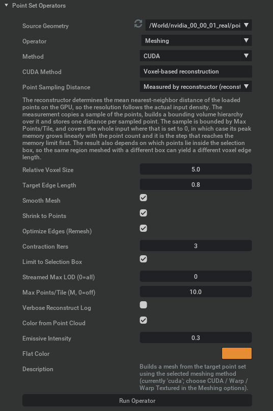
The Meshing operator in Selection Box > Point Set Operators reconstructs
a mesh directly from point cloud data using the local GPU. It is provided by
omni.pointcloud.ui in the Point Cloud Streaming Bundle.
Use this operator to reconstruct surfaces from the source points. For an image-based workflow that generates an asset from a viewport snapshot, refer to Generative Meshing.
Prerequisites#
Enable
omni.pointcloud.uiversion 1.1.8, or a compatible later version. This extension ships with Kit 110.4.Load a USD Points prim or a streamed point cloud (
NVSealedUsdArchive).For CUDA meshing, the application must include working
mesh_tools_libPython bindings. If the availability check fails, the panel displays a message.For streamed point clouds, use CUDA and enable Limit to Selection Box. Activate and position the Selection Box over the required region.
Meshing Methods#
Method |
Input |
Description |
|---|---|---|
CUDA (default) |
USD Points or streamed point clouds |
Voxel-based reconstruction with controls for resolution, optimization,
tiling, and color. Requires |
Warp |
A single USD Points prim |
Marching-cubes reconstruction using Warp. No additional parameters are exposed in the panel. |
Warp Textured |
A single USD Points prim |
Warp reconstruction with per-vertex color transfer from the point cloud. No additional parameters are exposed in the panel. |
The Warp methods do not require mesh_tools_lib, but do require a working
Warp runtime. Warp Textured transfers vertex colors; it does not create
texture images.
Create a Mesh#
Open Tools > Selection Box > Point Set Operators.
Select the Meshing operator and set Method to CUDA.
Position the Selection Box around the region you want to mesh. Leave Limit to Selection Box enabled.
Select Run Operator with the default settings.
Review the mesh in the Stage, then adjust resolution or surface refinement as needed.
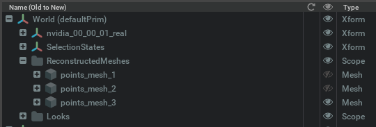
To combine multiple point cloud datasets, select (All Point Sets) and use CUDA. The operator gathers the supported sources in world space and creates one combined mesh. With Limit to Selection Box enabled, only points within the box contribute. Streamed sources are skipped when that option is disabled. Use a specific USD Points prim with either Warp method.
CUDA Parameters#
The read-only CUDA Method field displays Voxel-based reconstruction.
Resolution#
Mesh resolution depends on the point sampling distance, which represents the spacing between input points, and Relative Voxel Size:
Voxel edge length = Point sampling distance × Relative Voxel Size
Smaller voxels can capture finer detail, but require more processing time and GPU memory. Increasing resolution beyond the detail available in the source points does not add new detail.
Point Sampling Distance#
Choose how the sampling distance is determined.
Option |
Behavior |
When to use it |
|---|---|---|
|
Estimates spacing from the loaded points on the GPU. The estimate can change when the selection box changes. |
To adapt resolution to the density of the input points. |
|
Uses spacing information from the streamed dataset’s level of detail,
without an additional measurement pass or extra memory. Falls back to
|
To reduce measurement overhead when working with streamed datasets. |
|
Uses the value entered in Sampling Distance, in stage units. |
To use a fixed sampling distance across runs. |
With reconstructor, Max Points/Tile also limits the number of points used
to estimate spacing. Disabling this limit can substantially increase memory use
during measurement.
With octree, the sampling distance is reproducible for the same selection box
and Streamed Max LOD.
Sampling Distance#
Applies when Point Sampling Distance is set to explicit.
Enter a positive distance in stage units. The default, 0, is treated as unset.
A value smaller than the actual point spacing increases the voxel count without adding source detail.
A larger value reduces resolution and can bridge gaps between separate surfaces.
Relative Voxel Size#
Default: 5.0 · Range: 0.5–50
Controls voxel size relative to the point sampling distance.
Decrease it for finer reconstruction.
Increase it to reduce processing time and memory use.
Before reconstruction, the operator estimates the surface vertex count. If the estimate exceeds 120 million vertices, it stops and provides guidance. Increase Relative Voxel Size or reduce the selected region before trying again.
Surface Refinement#
These settings control the shape and triangle structure of the reconstructed mesh.
Parameter |
Default |
Description |
|---|---|---|
Target Edge Length |
0.8 |
Target triangle edge length as a fraction of the voxel edge length. Larger values produce coarser triangles. Range: 0.05–10. |
Optimize Edges (Remesh) |
On |
Adjusts triangle edges to produce a more regular mesh. This can make the surface look smoother even when Smooth Mesh is off. |
Smooth Mesh |
On |
Smooths the mesh during each optimization iteration. |
Shrink to Points |
On |
Moves mesh vertices toward the source geometry along their surface normals. |
Contraction Iters |
3 |
Number of contraction iterations applied before projection onto the source geometry. Higher values round off the initial voxel surface. Range: 0–10. |
Contraction Iters operates independently of the refinement toggles. Setting it to 0 disables contraction, but other enabled refinement settings can still change the surface.
To inspect the unrefined voxel surface, set Contraction Iters to 0 and turn off Optimize Edges (Remesh), Smooth Mesh, and Shrink to Points.
Limit to Selection Box#
This setting, Streamed Max LOD, and Max Points/Tile control how much data the operator loads and how it tiles reconstruction work.
Default: On
Reconstructs only the points inside the selection box. Use this to keep processing focused on a manageable region.
This setting is required for streamed datasets. If it is off, streamed datasets are skipped and a warning is logged.
Streamed Max LOD (0=all)#
Default: 0 · Range: 0–24
Limits the depth of point-cloud data loaded from a streamed dataset.
0 allows all available levels of detail.
1–24 caps the deepest level loaded. Lower caps load coarser data and reduce data volume.
Use a limit when loading large or remote datasets takes too long. Reducing the loaded detail can also reduce mesh detail.
This setting does not affect non-streamed point sets.
Max Points/Tile (M, 0=off)#
Default: 10 million · Range: 0–200 million
Divides reconstruction into tiles, each containing at most the specified number of points. The control displays values in millions.
The same limit also caps the sampling-distance measurement, helping control GPU memory use in both steps.
Set the value to 0 to disable tiling and process all input points in one pass. This can be faster and avoids duplicate geometry at tile boundaries, but memory use increases with the input point count.
Appearance#
Parameter |
Default |
Description |
|---|---|---|
Color from Point Cloud |
On |
Applies source point-cloud colors to mesh vertices. Where reconstruction does not supply colors, the operator transfers them from nearby source points. |
Emissive Intensity |
0.3 |
Controls material self-illumination, helping the mesh remain visible in unlit scenes. Lower it if the mesh appears overexposed. Range: 0–1. |
Flat Color |
Orange; RGB (0.9, 0.55, 0.2) |
Fallback color used when the mesh has no per-vertex colors. |
Source colors come from the point cloud’s displayColor data. Color transfer
remains available when Shrink to Points is off.
Troubleshooting#
Issue |
Suggested adjustment |
|---|---|
Reconstruction uses too much GPU memory |
Reduce the selection box size, increase Relative Voxel Size, or lower Max Points/Tile. For streamed data, use a smaller positive Streamed Max LOD limit. |
No points are inside the selection box |
Move or resize the box over the source. For a complete USD Points prim, disable Limit to Selection Box. |
The mesh lacks detail |
Decrease Relative Voxel Size. For streamed data, check whether Streamed Max LOD is limiting source detail. |
Separate surfaces are joined across gaps |
If using an explicit sampling distance, check that it is not larger than the actual point spacing. Consider reducing the voxel size. |
The surface looks too rounded |
Reduce Contraction Iters and review the smoothing and remeshing settings. |
Changing the selection box changes mesh resolution |
The default sampling-distance estimate depends on the selected points. Use a positive explicit Sampling Distance to keep voxel size consistent. |
A streamed dataset is skipped |
Confirm that CUDA is selected, the box overlaps the dataset, and Limit to Selection Box is enabled. |
CUDA bindings are unavailable |
Check the application’s |
The voxel estimate exceeds the guard |
Increase Relative Voxel Size or reduce the selected region. The guard rejects an estimated surface vertex count above 120 million, but smaller jobs can still exceed the available GPU memory. |
For more diagnostic information, enable Verbose Reconstruct Log. It is off by default and adds reconstruction progress and timing messages to the console.
Every run also logs a benchmark summary with the applied settings, input and output sizes, GPU kernel invocation count, and processing time for each step.
CUDA Meshing Examples#
Use these three starting presets to compare a quick preview, a balanced mesh, and a finer reconstruction. They are suggested tuning values, not built-in presets or benchmarked quality levels. Actual detail, runtime, and GPU memory use depend on point density, dataset extent, the selected region, and hardware.
Streamed Max LOD controls how much source detail is fetched from a streamed dataset. Relative Voxel Size controls reconstruction resolution, and Target Edge Length controls the remeshed triangle size. Finer triangles cannot recover features that are absent from the input points.
Common Setup#
Open Tools > Selection Box > Point Set Operators.
Select one point cloud in Source Geometry, set Operator to Meshing, and set Method to CUDA.
Position the Selection Box tightly around a representative object or region. Use the same source and box for all three examples.
Apply the common settings below, then choose the values for one example in the preset table and select Run Operator.
UI control |
Value |
|---|---|
CUDA Method |
Voxel-based reconstruction (read-only) |
Point Sampling Distance |
Measured by reconstructor (reconstructor) |
Sampling Distance |
Not shown in this mode. Leave measurement to the reconstructor. |
Limit to Selection Box |
On |
Smooth Mesh |
On |
Shrink to Points |
On |
Optimize Edges (Remesh) |
On |
Max Points/Tile (M, 0=off) |
10 (10 million points) |
Color from Point Cloud |
On |
Emissive Intensity |
0.3 |
Flat Color |
RGB (0.9, 0.55, 0.2). Used when vertex colors are unavailable. |
Verbose Reconstruct Log |
On, to compare reconstruction timings in the console. |
Example Settings#
UI control |
Example 1: Low detail |
Example 2: Medium detail |
Example 3: High detail |
|---|---|---|---|
Streamed Max LOD (0=all) |
6 |
10 |
0 (all available levels) |
Relative Voxel Size |
10.0 |
5.0 |
2.0 |
Target Edge Length |
1.2 |
0.8 |
0.5 |
Contraction Iters |
1 |
3 |
1 |
The LOD values 6 and 10 are initial trial values, not universal definitions of low and medium detail. Octree depth varies between datasets. If the dataset is shallower than either limit, that limit can already include all its levels. Increase the preview limit if it contains too few points, or decrease a positive limit to fetch less data. 0 means all levels, not the lowest detail.
For an ordinary USD Points prim, Streamed Max LOD has no effect. Use the remaining settings to compare reconstruction detail on the same input points.
Example 1: Low Detail, Fast Preview#
Use this preset to confirm the selected region and overall surface shape. The shallower streamed input, larger voxels, and coarser remeshing target are intended to reduce work. Expect less detail around small features, thin structures, and edges. One contraction pass limits additional processing for the preview.
Example 2: Medium Detail, Balanced Reconstruction#
Use this preset as the baseline for evaluating object shape and surface detail. Its voxel size, remeshing target, and contraction count match this extension’s defaults. The positive streamed LOD limit bounds the input depth; adjust it if your dataset needs deeper levels to represent the object clearly.
Example 3: High Detail, Longer Calculation#
Use this preset on a small region when fine features matter. It fetches all available streamed levels, uses smaller voxels, and requests finer triangles. It is intended to retain more source detail, with higher memory use and longer calculation than the other examples. One contraction pass reduces rounding of small features; it can also leave more noise or voxel structure visible.
This preset does not guarantee a highly detailed result from sparse data. If the voxel guard rejects the run or GPU memory is insufficient, reduce the box size first, or raise Relative Voxel Size from 2.0 to 3.0 or 5.0. Reducing Max Points/Tile can reduce part of the memory demand but does not guarantee that a reconstruction fits.
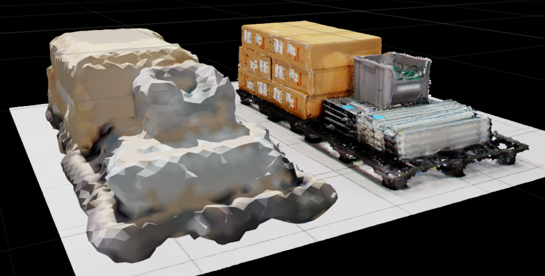
Mesh reconstruction with low/fast parameters.#
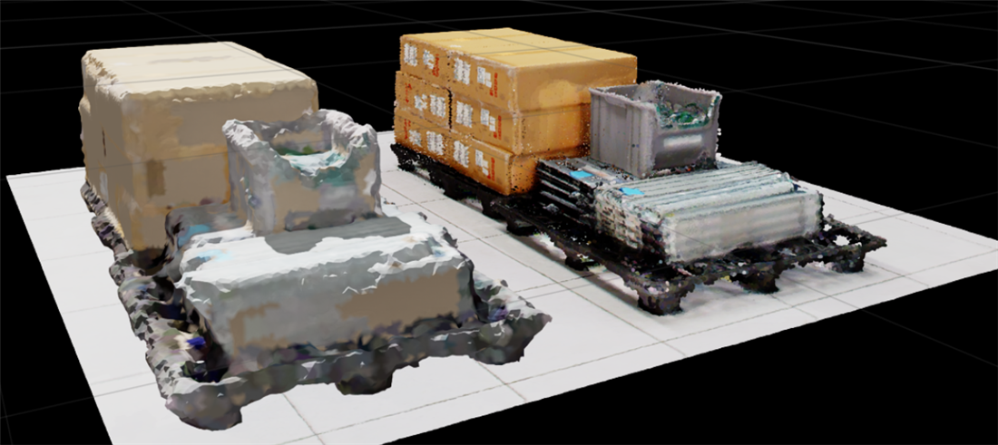
Mesh reconstruction with medium parameters.#
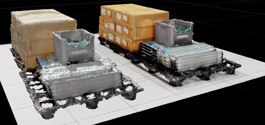
Mesh reconstruction with high/slower parameters.#
Compare the Results#
Inspect each mesh from the same viewpoint, showing one result at a time. Compare small features, gaps, surface noise, and triangle counts alongside the recorded timings. Streamed data can already be cached after the first run, so total run times are not directly comparable unless cache conditions are equivalent.
References#
NavVis IVION (site-specific configuration required)
omni.pointcloud.streaming.bundle extension (enable through Kit Extensions)
omni.usd.fileformat.e57extensionomni.usd.fileformat.ptsextension
You can use the Selection Box to filter Point Cloud data, run spatial operators, and save edited subsets to the Stage. To import or stream Point Clouds before editing, refer to Workflow User Guide. To configure render settings and viewport overlays, refer to Streamed Point Clouds UI.