Using Flow Control Nodes
Note
This doc contains features from OmniGraph version 2023.1.0.
In this tutorial, we explore the use of Flow Control Nodes in Action Graph.
Note
While you use Omniverse USD Composer in this tutorial, you can follow similar steps to achieve the same results in other Omniverse Apps.
Before You Begin
While this is an introductory-level tutorial on OmniGraph, we recommend you complete Introduction to OmniGraph and Using Event Source Nodes first. Those tutorials provide more detailed information about some of the same steps that you complete here.
What Are Flow Control Nodes?
Many Action Graphs need to do different things depending on some state. In a python script you would use an if or while loop to accomplish this. In Action Graph there are Flow Control Nodes which provide this branching functionality. Flow Control Nodes have one or more Execution Attribute outputs which are used to branch the evaluation flow.
Flow Control Nodes |
|---|
Note
Read more about Flow Control Nodes in the developer documentation.
Prepare the Stage
All of our examples start with the same setup:
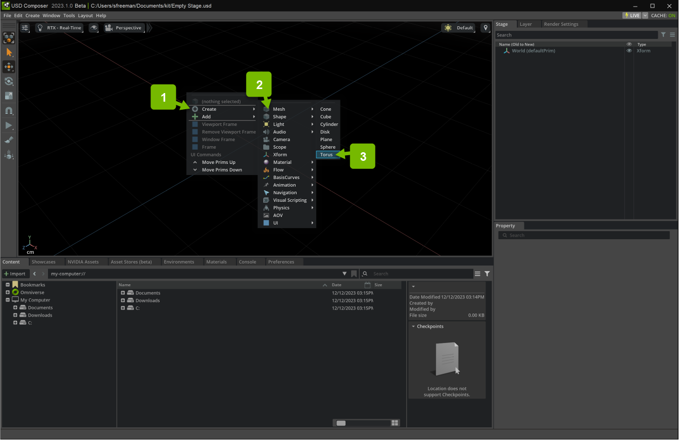
First, add a torus to the stage:
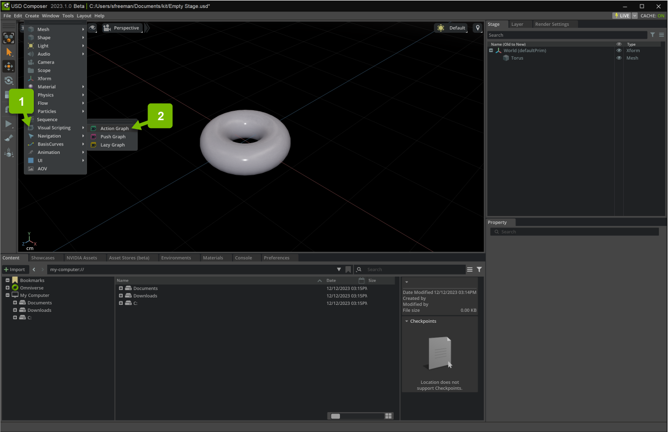
Next add a new Action Graph:
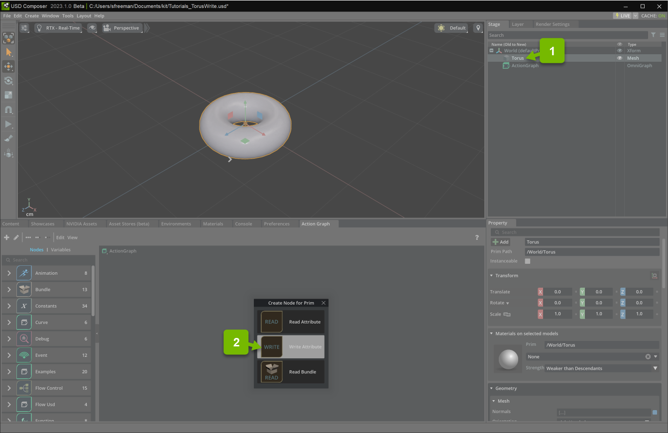
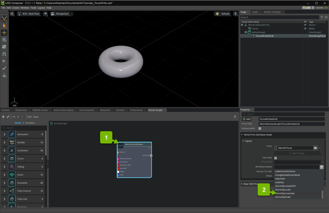
Drag your torus to the graph editor and create a WritePrimAttribute node:
Set the WritePrimAttribute node’s name attribute to xformOp:translate and the value attribute to (0.0, 20.0, 0.0):
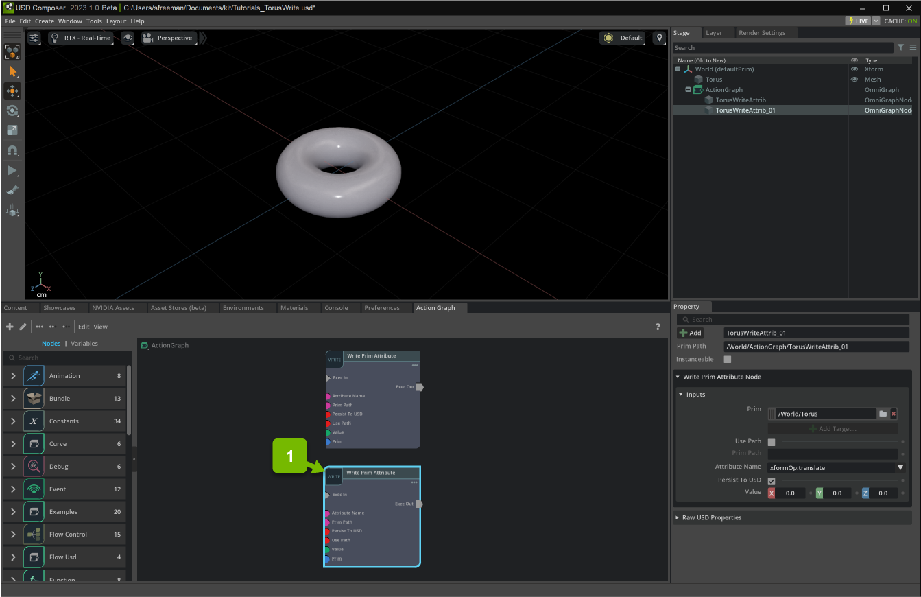
Duplicate that node with Ctrl+D so there are two WritePrimAttribute nodes. Set the new node’s value attribute to (0.0, 0.0, 0.0):
Note
You may need to reset the name attribute to xformOp:translate after you duplicate.
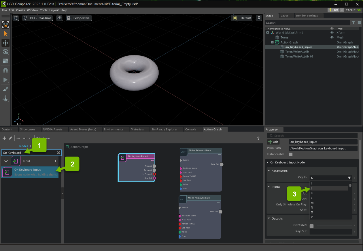
Lastly, create an OnKeyboardInput node, set the keyIn attribute to J:
Example 1: Flip Flop Node
In this example, we toggle the transformation of a mesh based on a keyboard input.
The Flip Flop is a flow control node that alternates its outputs.
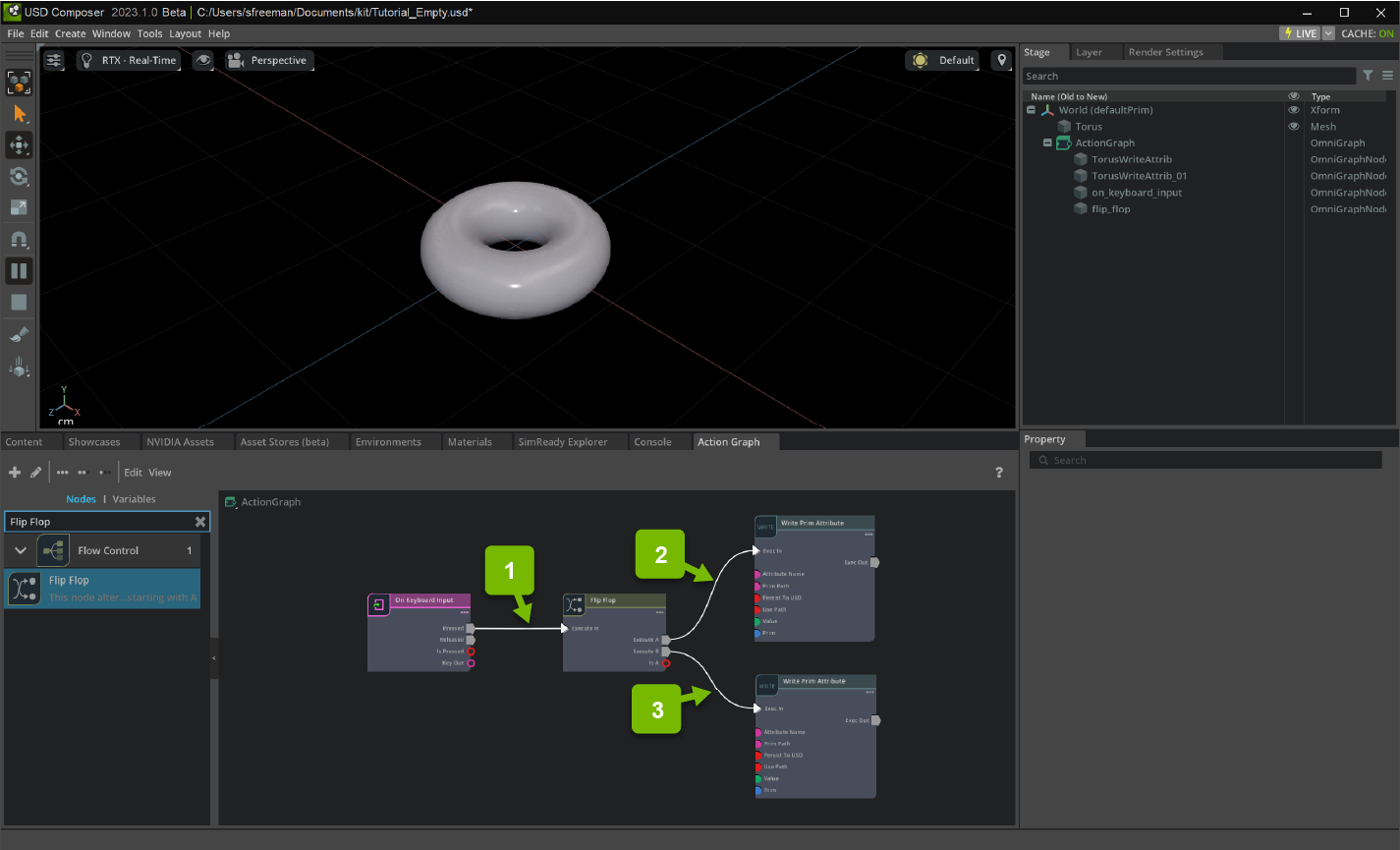
First, create a FlipFlop nodes:
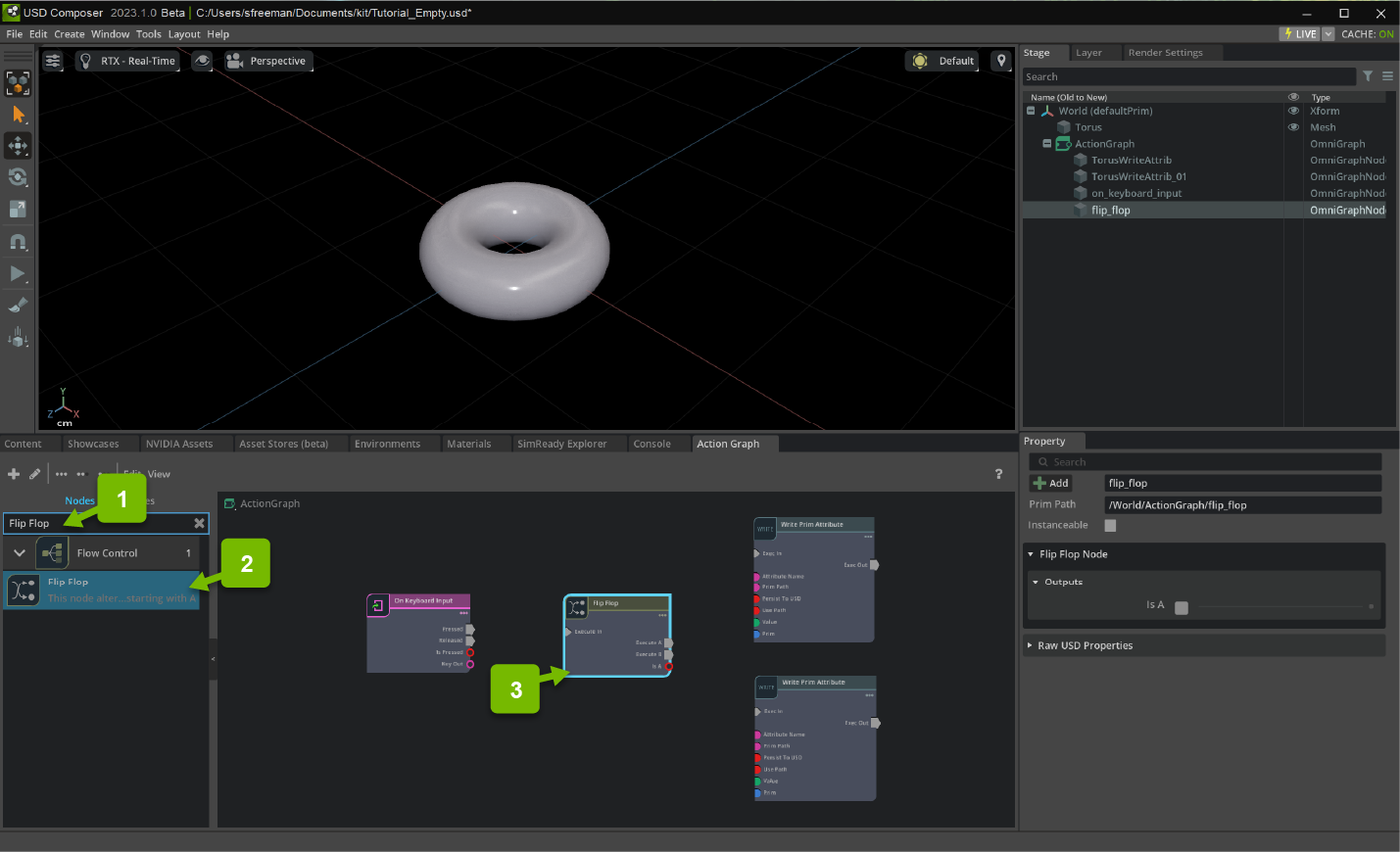
Now, connect the Pressed output of the OnKeyboardInput to the Execute In input of the FlipFlop node.
Then connect the Execute A output to the Exec In input of the first WritePrimAttribute and Execute B output to the Exec In input of the second WritePrimAttribute.
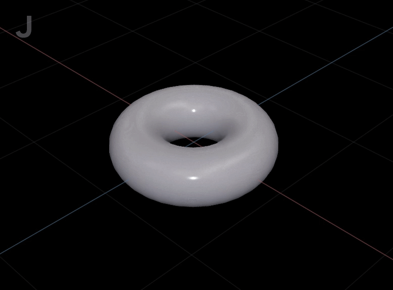
Now press Play. Every time the J key is pressed, the torus alternates between (0.0, 20.0, 0.0) and (0.0, 0.0, 0.0).
Example 2: Multi Gate Node
In this example, we toggle between multiple different transformations based on a keyboard input.
The Multigate is a flow control node the cycles through all of its inputs.
First, duplicate a WritePrimAttribute.
Then, create a Multigate node:
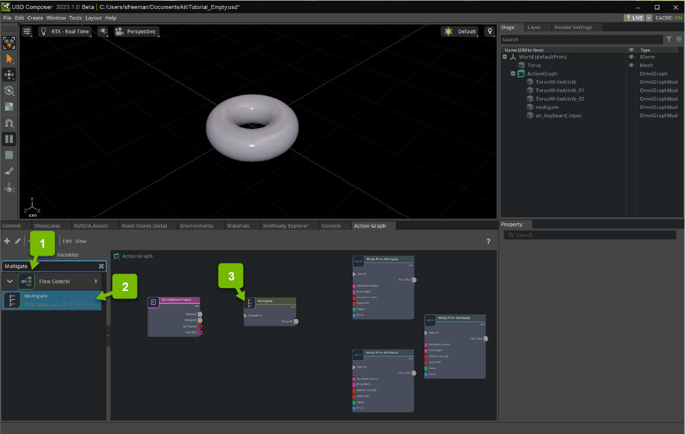
Next, create two new outputs on the Multigate node by clicking the + button in the Property Panel:
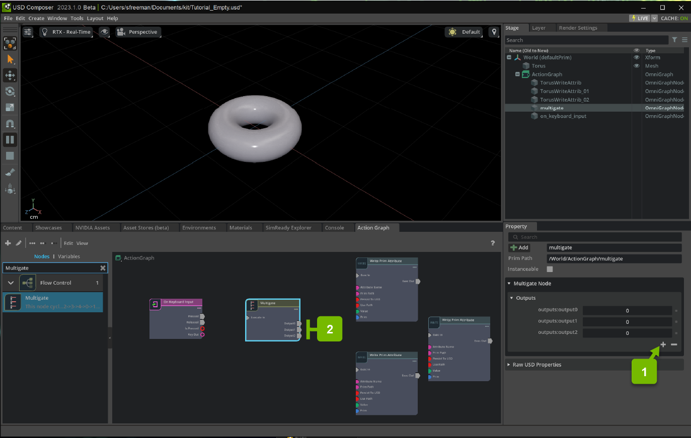
- Connect Pressed to Execute In, then
Output0 to Exec In of the first WritePrimAttribute node and set value to
(0.0, -20.0, 0.0)Output1 to Exec In of the second WritePrimAttribute node and set value to
(0.0, 20.0, 0.0)Output2 to Exec In of the third WritePrimAttribute node and set value to
(0.0, 0.0, 0.0)
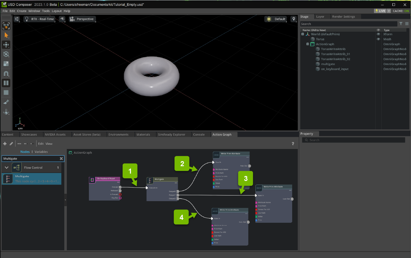
Now press Play. Every time the J key is pressed, the torus cycles between (0.0, 20.0, 0.0), (0.0, 0.0, 0.0) and (0.0, -20.0, 0.0).