Graph Concepts#
This article covers core graph concepts found in EF. Readers are encouraged to review the Execution Framework Overview before diving into this article.

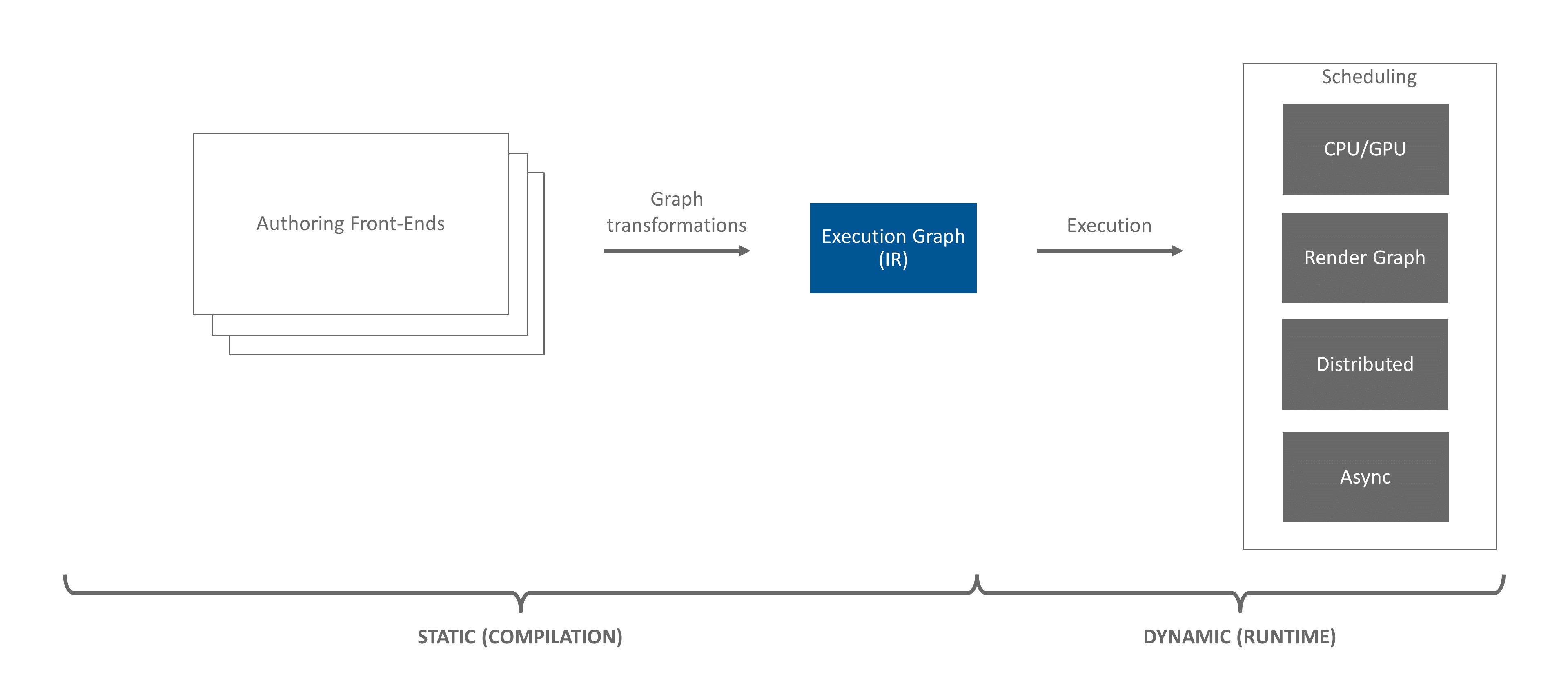
Figure 7 The Execution Framework pipeline. This article covers concepts found in the Execution Graph (IR).#
The core data structure Execution Framework (EF) uses to describe execution is a graph of graphs. Each graph contains a root node. The root node can connect to zero or many downstream nodes via directed edges.
Nodes represent work to be executed. Edges represent ordering dependencies between nodes.
Figure 8 A simple graph.#
The work each node represents is encapsulated in a definition. Each node in the graph may have a pointer to a definition. There are two categories of definitions: opaque and graph.
An opaque definition is a work implementation hidden from the framework. An example would be a function pointer.
The second type of definition is another graph. Allowing a node’s work definition to be yet another graph is why we say EF’s core execution data structure is a graph of graphs.
The top-level container of the graph of graphs is called the execution graph. The graphs to which individual nodes point are called graph definitions or simply graphs.
The following sections dive into each of the topics above with the goal of providing the reader with a general understanding of each of the core concepts in EF’s graph of graphs.
Nodes#
Nodes in a graph represent work to be executed. The actual work to be performed is stored in a definition, to which a node points.
Nodes can have both parent and child nodes. This relationship between parent and child defines an ordering dependency.
The interface for interacting with nodes is INode. EF contains the Node implementation of INode for instantiation
when constructing graph definitions.
Each node is logically contained within a single graph definition (i.e. INodeGraphDef).
Edges#
Edges represent ordering between nodes in a graph definition. Edges are represented in EF with simple raw pointers
between nodes. These pointers can be accessed with INode::getParents() to list nodes that are before a
node, and INode::getChildren() to list nodes that are after the node.
Definitions#
Definitions define the work each node represents.
Definitions can be opaque, meaning EF has no visibility into the actual work being performed. Opaque definitions
implement the INodeDef interface. Helper classes, like NodeDefLambda exists to easily wrap chunks of code into an
opaque definition.
Definitions can also be defined with a graph, making the definitions transparent. The transparency of graph definitions enables EF to perform many optimizations such as:
Execute nodes in the graph in parallel
Optimize the graph for the current hardware environment
Reorder/Defer execution of nodes to minimize lock contention
Many of these optimizations are enabled by writing custom passes and executors. See Pass Creation and Executor Creation for details.
Graph definitions are defined by the INodeGraphDef interface. During graph construction, it is common for IPass
authors to instantiate custom graph definitions to bridge EF with the authoring layer. The NodeGraphDef class is
designed to help implement these custom definitions.
Definition instances are not unique to each node. Definitions are designed to be shared between multiple nodes.
This means two different INode instances are free to point to the same definition instance. This not only saves
space, it also decreases graph construction time.
Figure 9 A simple graph showing pointers from nodes to definitions.#
Above we see the graph from Figure 8, but now with pointers to definitions (dashed lines). Notice how definitions are shared between nodes. Furthermore, notice that nodes in graph definitions can point to other graph definitions.
Both INodeDef (i.e. opaque definitions) and INodeGraphDef (i.e. graph definitions) inherit from the IDef
interface. All user definitions must implement either INodeDef or INodeGraphDef.
Definitions are attached to nodes and can be accessed with INode::getDef(). Note, a node is not required to have
a definition. In fact, each graph’s root node will not have an attached definition.
Execution Graph#
The top-level container for execution is the execution graph. The execution graph is special. It is the only entity, other than a node, that can contain a definition. In particular, the execution graph always contains a single graph definition. It is this graph definition that is the actual graph of graphs. The execution graph does not contain nodes, rather, it is the execution graph’s definition that contains nodes.
In addition to containing the top-level graph definition, the execution graph’s other jobs are to track:
If the graph is currently being constructed
Gross changes to the topologies in the execution graph. See invalidation for details.
The execution graph is defined by the IGraph interface. EF contains the Graph implementation of IGraph for
applications to instantiate.
Topology#
Each graph definition owns a topology object. Each topology object is owned by a single graph definition.
The topology object has several tasks:
Owns and provides access to the root node
Assigns each node in the graph definition an unique index
Handles and tracks invalidation of the topology (via stamps)
Topology is defined by the ITopology interface and accessed via INodeGraphDef::getTopology().
Root Nodes#
Each graph definition contains a topology which owns a root node. The root node is where traversal in a graph definition starts. Only descendants of the root node will be traversed.
The root node is accessed with ITopology::getRoot(). Use of ITopology::getRoot() is often seen during the
construction of a graph definition.
Root nodes are special in that they do not have an attached definition, though a graph definition’s executor may assign special meaning to the root node.
Root nodes are defined by the INode interface, just like any other node.
Each graph definition (technically the graph definition’s topology) has a root node. This means there are many root nodes in EF (i.e. EF is a graph of graphs).
Next Steps#
In this article, an overview of graph concepts was provided. To learn how these concepts are utilized during graph construction, move on to Pass Concepts.