


Working with Nodes#
Nodes are the building blocks of every material in Material Graph. This page covers the full lifecycle of working with them: creating nodes, wiring them together, selecting and arranging them, and organizing them into groups.
Creating Nodes#
There are three ways to add a node to the canvas.
Drag from the Catalog#
Open the Catalog panel on the left side of the editor. If it is hidden, enable Show Catalog in Material Graph preferences.
Select the Nodes, NodeGraphs, or Textures tab depending on what you want to add.
Browse the categorized list or type in the search field to filter.
Click and drag an entry from the Catalog onto the canvas.
Release the mouse button to place the node at the drop position.
Quick Search#
If the omni.kit.window.quicksearch extension is enabled, you can add nodes without reaching for the Catalog panel.
Press the Quick Search shortcut to open the overlay.
Start typing the name of the node you need. Results are grouped into Nodes, NodeGraphs, and Textures sections and filtered in real time.
Click a result or press Enter to place it on the canvas at the current graph position.
Quick Search respects the active render context, so only nodes available in the current context appear in the results.
Node Types#
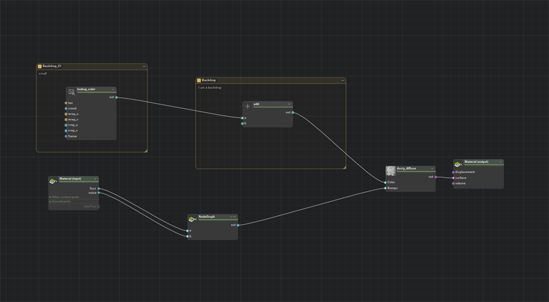
Material Graph uses three fundamental node types, each backed by a different USD prim type.
Type |
USD Prim |
Purpose |
|---|---|---|
Shader |
|
Performs a single operation, such as surface shading, texture lookup, math, or value generation. These nodes are the functional workhorses of every graph. |
NodeGraph |
|
A container that encapsulates a sub-graph of nodes. Use NodeGraphs to organize complex materials into logical sections or to create reusable building blocks. |
Backdrop |
|
A colored, labeled rectangle behind nodes. Backdrops contain no shader logic and are organizational. Refer to Backdrops and Layout for details. |
Connecting Ports#
Nodes communicate by passing data through connections between their ports.
Making a Connection#
Click the output port dot on the right edge of the source node.
Drag toward the destination node. As you drag, compatible input ports are highlighted and incompatible ones are dimmed.
Release over a highlighted input port on the left edge of the target node to complete the connection.
A wire now links the two ports. Data flows from left to right.
Port Type Compatibility#
Each port has a typed connector. The editor color-codes ports by data type. For example, float ports share one color and color3f ports share another, which helps you identify compatible pairs.
When you drag a wire, the editor evaluates type compatibility between the source output and every potential target input. Compatible ports appear highlighted; incompatible ports are dimmed. The wire preview itself changes color during the drag:
Wire Color |
Meaning |
|---|---|
Green |
The connection is valid. |
Gray |
Default state (no target under the cursor). |
Red / Blue |
The connection is rejected for incompatible types, a self-wire, or same-side ports. |
Rewiring an Existing Connection#
To change where an input receives its data:
Click the connected input port (the port that already has a wire attached).
Drag the wire away from that port and onto a different output port on another node.
Release to complete the rewire.
The old connection is removed and the new one is created in a single undo step. If you release the drag over empty canvas space instead of a valid port, the original connection is disconnected.
Force Connect#
You might need to create a connection that the editor’s type checks normally reject. You can override the checks in two ways:
Modifier key: Hold Ctrl+Shift while dragging the wire. The editor bypasses type compatibility validation for that connection attempt. Cycle detection and same-prim self-wire restrictions still apply.
Global setting: Enable Force Connect in Preferences (
persistent.app.properties.materialGraph.forceConnect). When enabled, all connection drags skip type checks without requiring the modifier key.
Tip
Force Connect is useful when you know the downstream render engine performs an implicit type conversion. You can also use it when prototyping a graph before all node definitions are finalized.
Selecting Nodes#
Single Selection#
Click a node to select it. This deselects any previously selected nodes.
Multi-Selection#
Action |
Behavior |
|---|---|
|
Toggle the node in or out of the current selection. |
|
Add the node to the current selection. |
Marquee (Rectangle) Selection#
Click and drag on an empty area of the canvas to draw a selection rectangle. Every node whose bounds intersect the rectangle is selected when you release.
Modifier |
Behavior |
|---|---|
No modifier |
Replace the current selection with the nodes in the rectangle. |
|
Add the nodes in the rectangle to the current selection. |
|
Remove the nodes in the rectangle from the current selection. |
Deselecting#
Click an empty area of the canvas (without Shift or Ctrl held) to clear the selection.
Moving Nodes#
Click and drag any selected node to move the entire selection. All selected nodes maintain their relative positions during the move.
If you click and drag a node that is already part of a multi-selection, the whole group moves together. If the node is not selected, clicking it first replaces the selection with that single node, then begins the drag.
Deleting Nodes#
Select one or more nodes and press Del to delete them. You can also right-click a selected node and choose Delete from the context menu.
Deleting a node automatically removes all connections to and from that node. The deletion is recorded in the undo history, so you can press Ctrl+Z to restore deleted nodes and their connections.
Node Expansion States#
Every node can be displayed in one of three visual states, controlled by keyboard shortcuts:
Key |
State |
Description |
|---|---|---|
|
Open |
Full view with the header, accent line, and all ports visible. |
|
Minimized |
Compact view that uses less vertical space while still showing the node identity. |
|
Closed |
Collapsed to the header only, hiding all ports. Connected wires remain attached. |
Pressing the key applies the state to nodes in the current graph level. You can also cycle through states by clicking the expansion chevron in the node header, which follows the sequence Open → Minimized → Closed → Open.
Tip
Use Minimized or Closed states to reduce visual clutter in large graphs while keeping the logical structure intact. Connections remain visible even when a node is closed.
Grouping Nodes into NodeGraphs#
Creating a Group#
Select the nodes you want to group. All selected nodes must be at the same graph level (under the same parent).
Press Ctrl+G.
A new NodeGraph container is created. The selected nodes are moved inside it, and input/output interface ports are added automatically to maintain existing external connections.
Ungrouping#
Select one or more NodeGraph containers.
Press Ctrl+U.
The contents of each selected NodeGraph are extracted back to the parent level, and the container is removed. Connections are rewired to preserve the data flow.
Tip
Grouping and ungrouping are fully undoable. Press Ctrl+Z immediately after if the result is not what you expected.
Summary of Keyboard Shortcuts#
Shortcut |
Action |
|---|---|
|
Set nodes to Open expansion |
|
Set nodes to Minimized expansion |
|
Set nodes to Closed expansion |
|
Delete selected nodes |
|
Group selection into a NodeGraph |
|
Ungroup selected NodeGraphs |
|
Frame selection (or all nodes if nothing is selected) |
|
Auto-layout |
|
Force Connect (bypass type checks) |
For the complete reference, refer to Hotkeys and Mouse Reference.