Usage#
The user can then import the DGN file into Omniverse via two workflows: via File Menu Window or via the Content Window.
How to Import and Convert Files#
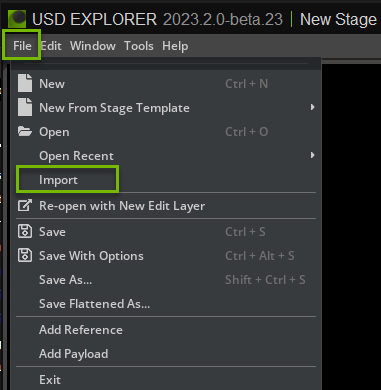
File -> Import#
To import a CAD file into Omniverse, choose
Importin theFilemenu.The user should now see a window similar to a file manager. The user needs to then select a DGN file for conversion from this window.
Refer to Converter Options section for more information on conversion settings.
Import through the Content Window#
By default the Content window is located at the bottom of the Omniverse App. To convert a CAD file to USD, select the file in the Content window and choose
Convert to USDin the context menu with right mouse button.Browse to the location of your file or files, select them, and right-click, and select
Convert to USDin the Context menu.The Converter Options dialog window will appear, modify any options as needed, and click Convert.

Note: The
ContentWindow tab provides a file browser interface for navigating and managing files. If it is not shown, go to the Menu toolbar, select “Window”, and then select “Content”.
Converter Options#
The DGN converter provides several options to control how files are converted:
Stage Metrics Options#
These options modify the stage’s metersPerUnit and upAxis settings, applying relevant transformations to maintain proper world space units.
Option |
Description |
|---|---|
Override Up-Axis |
Override the stage’s up-axis to Y-up, Z-up, or use converter default |
Meters Per Unit |
Set the stage’s meters per unit metric (0.0 retains original conversion value) |
Conversion Options#
Option |
Description |
|---|---|
Mesh Conversion Style |
Controls how mesh elements are converted. Options: None (skip mesh conversion), Attributes (metadata only, authored as Xform with transform), Renderable (convert to both geometry and USD attributes). |
Curve Conversion Style |
Controls how non-text curve elements are converted. Options: None (skip curve conversion), Attributes (metadata only, authored as Xform with transform), Renderable (convert to both geometry and USD attributes). |
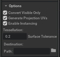
Convert Visible Only |
If enabled, skips hidden elements. If disabled, converts hidden elements but sets them to invisible. |
Instancing Style |
When instancing is enabled (Instancing Style set to “Scenegraph Instancing”), the DGN converter creates USD instancing structures to efficiently represent Shared Cell References from the DGN file. For detailed information about how instancing is authored, why class prims are used for prototypes, and how to work with prototype prims for debugging, see Instancing in USD. |
Material Options#
Material Type |
Description |
|---|---|
None |
No materials generated |
Preview Surface |
Default option, creates a simple preview surface material compatible with Universal renderer |
OmniPBR |
Creates a physically based material compatible for RTX and Universal renderers |
Note: For more information about materials, see Materials Templates documentation
Advanced Options#
Option |
Description |
|---|---|
Generate Projection UVs |
When UV texture coordinates are missing, uses Scene Optimizer Kit Extension to generate texture coordinates for meshes. Uses default values as described in the Generate Projection UVs documentation. |
Convert Element ID |
When enabled, DGN element IDs are converted to custom USD attributes or primvars |
Merge Meshes |
When enabled, meshes sharing the same level, color, and element type are merged for optimization. When disabled, mesh merging is skipped. |
Merge Curves |
When enabled, curves are merged for optimization |
Use Materials |
When enabled, materials from the source file are converted to USD materials. When disabled, converter creates materials with the color set as an attribute or converts colors to USD |
Triangulate |
When enabled, all polygons are triangulated during conversion |
Apply Global Origin |
When enabled, applies the global origin transformation to the converted scene. When disabled, the value is stored as an attribute but the Model has no transform applied. |
Fallback Curve Width |
Default curve width when not specified in source. Set to -1 to use source default. |
Geometry Attribute Style |
Controls how DGN geometry attributes are authored to USD. Options: None (don’t author attributes), Attribute (default, author as a custom attribute), Primvar (author as a constant primvar) |
Merged Attribute Style |
Sets the attribute style for merged geometry. Options: None (no attributes on merged geometry), Primvar (store attributes as primvars), Subset (store attributes using geometry subsets) |
Verbose Logging |
When enabled, verbose logging will be reported to omni logs and the console during conversion. Useful for debugging conversion issues or when detailed conversion reports are required. |
Level and Attribute Filtering#
These options control which content from the DGN file is imported. All list fields accept comma-separated values with wildcard support (* matches any sequence of characters). Type plain tokens separated by commas—do not wrap each token in JSON-style double quotes (unlike the quoted strings in a JSON config file).
Option |
Description |
|---|---|
Level Filter Style |
None, Omit, Deactivate (convert but deactivate filtered), Hide (convert but hide filtered) |
Level Includes |
Comma-separated list of level name patterns to include. Defaults to |
Hide Levels By List |
When enabled, levels matching the Hidden Levels list are excluded or hidden during conversion |
Hidden Levels |
Comma-separated list of level name patterns to hide. Only active when Hide Levels By List is enabled. Example: |
Level Exclude Hidden |
When enabled, levels matching the Level Excludes list are excluded from conversion |
Level Excludes |
Comma-separated list of level name patterns to exclude. Only active when Level Exclude Hidden is enabled. Example: |
Model Name Patterns |
Comma-separated list of model name patterns to include. Example: |
Import Attributes By List |
When enabled, only the attributes listed in the Attributes field are imported from the source file |
Attributes |
JSON array of attribute mapping objects. Only active when Import Attributes By List is enabled. Each entry must include |
Note: If the Attributes field contains invalid JSON when you click Convert, the conversion will be cancelled and a warning notification will be shown. The field must be either empty or a valid JSON array.
Tessellation Control#
Tessellation options control mesh accuracy versus performance. These settings determine how surfaces are converted into triangular meshes.
Surface Tolerance#
The surface tolerance setting controls mesh accuracy versus performance:
Tolerance Range |
Use Case |
Result |
|---|---|---|
Low (0.001 - 0.01) |
High precision needs |
More detailed mesh, larger files, slower processing |
High (0.1 - 1.0) |
Visualization (recommended) |
Less detailed mesh, smaller files, faster processing |
Default value is 0.2 for balanced performance and quality. Setting to 0 automatically uses 2.5% of model’s bounding box diagonal.
Note: For detailed information about tessellation, see Open Design Alliance’s blog post
Additional Tessellation Options#
Option |
Description |
Default |
|---|---|---|
Normal Tolerance |
Maximum angle (in degrees) between adjacent face normals. Smaller values produce smoother surfaces with more triangles. Controls tessellation quality of circular surfaces (Cone, Torus, Sphere, Cylinder). Measured in degrees, determines quantity of mesh cells (360/NormalTolerance). |
15.0 |
Between Knots |
Number of points to add between knots when tessellating curves. For NURB surfaces, contains number of additional isolines between knots. |
2 |
Grid Aspect Ratio |
Grid aspect ratio for tessellation. Set to 0 for automatic calculation. |
0.0 |
Max Facet Edge Length |
Maximum facet edge length for tessellation. Set to 0 for no limit. |
0.0 |
Max Grid Lines |
Maximum number of grid lines for tessellation. |
10000 |
Points Per Edge |
Points per edge for curve tessellation. Set to 0 for automatic calculation. |
0 |
Text 3D Options#
Text conversion options control how 3D text elements such as OdDgTextNode3d and OdDgText3d from DGN files are converted to USD.
Option |
Description |
Default |
|---|---|---|
Text 3D Conversion Style |
Controls how 3D text elements (OdDgText3d and OdDgTextNode3d) are converted. None – skip 3D text conversion entirely; Attributes – author as USD attributes only (no geometry); Renderable – convert to Basis Curves and author attributes in a separate layer. |
None |
Curve Sample Points |
Number of sample points to use when approximating curve for OdDgText3d and OdDgTextNode3d objects. |
8 |
Text 3D Width |
Sets the width for Basis Curves converted from OdDgText3d and OdDgTextNode3d elements. |
0.05 |
Output Options#
Option |
Description |
|---|---|
Path |
Destination folder for converted USD (defaults to source location) |
Scene Optimizer Config |
Path to Scene Optimizer JSON config file or JSON string for predefined optimization stack. See Scene Optimizer Service documentation. |
Getting Help#
The Developer Community can also ask questions or report issues on Omniverse Developer forums.