Example: Points Based Dataset#
Import and Orient Data#
Launch Kit-CAE.
Click File > Import and browse to the directory containing the example files.
File > Import and select
concept_car.npz.Under options, select Point Cloud.
Check Allow Pickle.
Select Import to Stage.
Select Import.
Follow the same steps above and import physicsnemo_results.npz.
Orient the Model#
In Stage/World go to Property > Transform and select Orient.
Add rotation about X of -90 degrees and then press Enter.
Visualizing Data with Points#
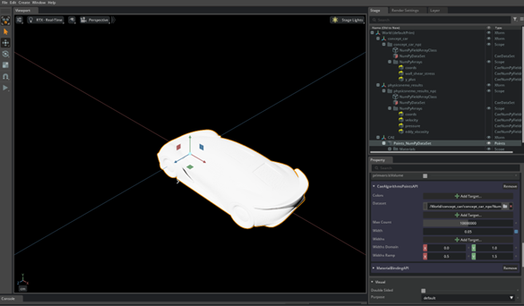
A quick way to visualize what data is available in the dataset is by using points. Points create spheres at every vertex location in the dataset, providing a clear visualization of the dataset’s structure. In the next example we will visualize the surface of the car (aero_suv) by points.
Create Points#
Select the
concept_car_npz/NumPyDataSetnode in the Stage panel.Right-click on the node to get the context menu.
Navigate to and select Create > CAE Algorithms > Points.
Expand the newly created
/CAEnode and you will seePoints_NumPyDataSetnode under it.In
CAE/Points_NumPyDataSet/Propertynavigate to CaeAlgorithmsPointsAPI.Change the Width to 0.05.
Create a Bounding Box/Region of Interest#
In Stage/World/concept_car_npz, right-click on NumPyDataSet node to open the context menu.
Navigate to, and select Create > CAE Algorithms > Bounding Box.
This creates and automatically highlights a new node:
/CAE/BoundingBox_NumPyDataSet.
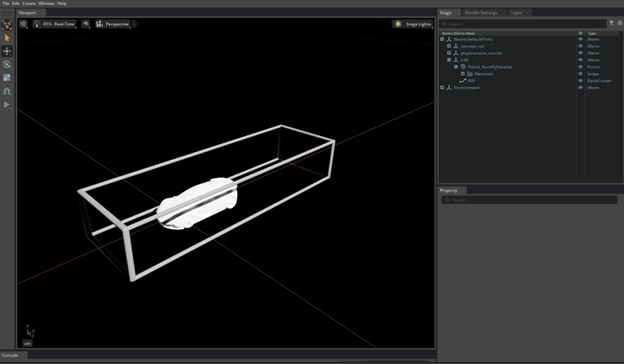
Rename the Bounding Box to ROI (Region of Interest)#
In Stage/CAE/BoundingBox_NumPyDataSet under Property, double-click on the name to the right of +Add and change it to ROI.
In Stage/CAE/ROI go to Property > Transform and select Add Transforms.
Scale by X: 3, Y: 2 and Z: 2.
Position the ROI around the vehicle to be sure to include the full wake in the ROI.
Zoom into the Bounding Box#
Hit F on the keyboard to fit the model to the screen.
Create Streamlines (NanoVDB based)#
Hide the ROI created in previous step (optional)#
Select the eye icon in the stage panel next to the ROI (bounding box created in the previous step) to toggle off the display.
Create a Unit Sphere#
In Stage/World/physicsnemo_results, right-click on the
NumPyDataSetnode to open the context menu.Navigate to, and select Create > CAE Algorithms > Unit Sphere.
This creates a new prim named
/CAE/UnitSphere.
Scale the Unit Sphere#
In Stage/CAE/UnitSphere under Property/Transform, select Add Transformation.
Ensure the chain symbol is highlighted under transform - this scales the object uniformly in all three directions.
Double-click on, or Cntrl-click, the value 1 in one of the boxes in X, Y or Z and change it to 0.1.
Position the UnitSphere in front of the vehicle by selecting highlighting Stage/CAE/UnitSphere and interactively moving it in the viewer window.
Create the Streamlines#
In Stage/World/physicsnemo_results, right-click on the NumPyDataSet node to open the context menu.
Navigate to, and select Create > CAE Algorithms > Streamlines (NanoVDB). This creates a new primitive
/CAE/NanoVdbWarpStreamlines_NumPyDataSet.In Stage/CAE/NanoVdbWarpStreamlines_NumPyDataSet/Property scroll to the CaeAlgorithmsWarpStreamlinesAPI section.
Next to Seeds, select Add Target and navigate to, and select, the UnitSphere created in the prior section (
/CAE/UnitSphere).Next to Velocity, select Add Target and navigate to the velocity data (
physcisnemo_results/NumPyArrays) select velocity and hit Select.Because the domain is very large, and we are only interested in the region near the vehicle, we will use a Region of Interest to reduce the streamlines to only near the vehicle.
Move the Unit Sphere to update the location of the streamlines in real time.
Navigate to CAE/NanoVdbWarpStreamlines_NumPyDataSet/Property/CaeAlgorithmsWarpStreamlinesAPI, select Add Target to the right or Region-of-interest (ROI), navigate to, and select ROI created in the previous step. The streamlines will be contained to the ROI.
The colors of the streamlines can be adjusted in World/CAE/NanoVdbWarpStreamlines_NumPyDataSet/Materials/ScalarColor/Shader.
The min and max values of the color bar can be changed by updating the values in Property/Shader/Inputs/domain where X is min and Y is max.
The color map applied to the streamlines can be changes at: World/CAE/NanoVdbWarpStreamlines_NumPyDataSet/Materials/ScalarColor/Shader/Property/Shader/Inputs/lut. The following color maps come with the build:
afmhot
cividis
gist_gray
gist_rainbow (default)
Other important parameters for Streamlines are set at World/CAE/NanoVdbWarpStreamlines_NumPyDataSet/Property/CAE NanoVSB Streamlines:
dx: step size between streamline vertices.
Max Length: The maximum distance the streamlines will be displayed.
Max Resolution: Controls the voxelization of the region where the streamlines will be displayed.
Region of interest: Specifies a region to create the streamlines in. This is useful when working with simulation results with a large domain size, the ROI can be used to subset the volume into a smaller region of interest.
Width: Width of the display of the streamlines.
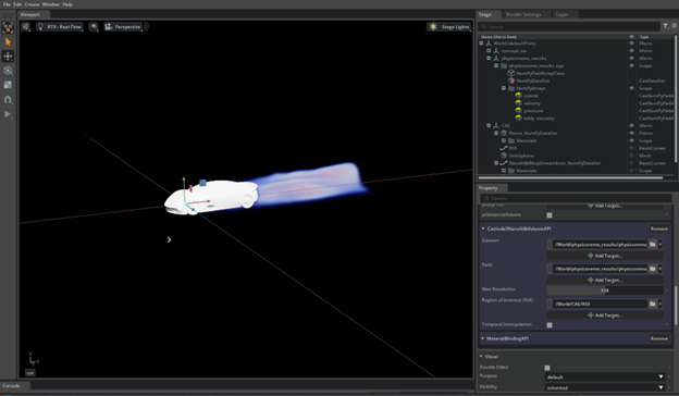
Create Volume Rendering: Volume (NanoVDB+IndeX)#
Hide the Streamlines created in the previous step.
In Stage/World/physicsnemo_results, right-click on the
NumPyDataSetnode to open the context menu.Navigate to, and select Create > CAE Algorithms > Volume (NanoVDB + IndeX).
This creates another prim named
/CAE/NanoVdbIndeXVolume_NumPyDataSet.
In Stage/CAE/NanoVdbIndeXVolume_NumPyDataSet/Property scroll to the CaeIndeXNanoVdbVolumeAPI section.
Select Add Target next to Region-of-Interest (ROI) and select the ROI created in the previous step.
Select Add Target next to Field and navigate to the flow results (
physcisnemo_results/NumPyArrays/). Select eddy_viscosity and hit select.
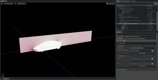
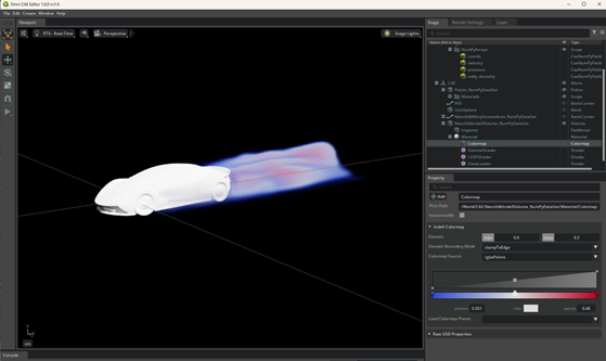
You should see the following:
The visual display can be adjusted via the Colormap under Stage/CAE/NanoVdbIndeXVolume_NumPyDataSet/Material/Colormap/Property.
In the IndeX Colormap section, change the Domain min to 0 and max to 0.2.
Below the Colormap Source, in the middle of the Property panel, there is an interactive gradient adjuster which controls the color and translucency of the flow field. Select the middle circle, move it down to the bottom, and then move the placeholder object slightly to the right as shown below.
Create Flow Visualization#
Hide the Volume render created in the previous step.
In Stage/World/physicsnemo_results, right-click on the NumPyDataSet node to open the context menu. Navigate to and click on Create > CAE Flow > Environment.
This creates another prim named /CAE/FlowEnvironment.
Right-click on the node to retrieve the context menu and navigate to and click on Create > CAE Flow > DataSet Emitter.
This creates another prim named /CAE/DataSetEmitter_Volume_elements.
Right-click on the node to retrieve the context menu and navigate to and click on Create > CAE Flow > VolumeStreamlines.
This creates another prim named /CAE/VolumeStreamlines.
In /CAE/DataSetEmitter_NumPyDataSet navigate to Data.
Next to Temperature > Add Target, navigate to and select pressure.
Next to Velocity > Add Target, navigate to and select velocity.
Expand VolumeStreamlines and select EmitterSphere.
Navigate to Property > Radius and change the radius to 0.5.
Select VolumeStreamlines and move the Sphere in front of the vehicle.
On the menu on the left, hit the play button. An animation will be shown.
Create Slice Planes#
Hide the Flow Visualized created in the previous step.
In Stage/World/physicsnemo_results, right-click on the
NumPyDataSetnode to open the context menu. Navigate to and click on Create > CAE Flow > Slice (NanoVDB).This creates another prim named /CAE/IndeXNanoVdbSlice_NumPyDataSet.
In /CAE/IndeXNanoVdbSlice_NumPyDataSet, navigate to Slice (NanoVDB), and then Region-of-interest (ROI), and select Add Target.
Select the ROI created in the previous step.
In /CAE/IndeXNanoVdbSlice_NumPyDataSet, navigate to Extra Properties, find Field, and then select Add Target.
Navigate to and select pressure from physicsnemo_results_npzNumPyArrays.
Expand /CAE/IndeXNanoVdbSlice_NumPyDataSet. Select Plane, translate over desired slice region.
Duplicate plane translate and rotate to the desired region (optional).