Omni Physics Deformable Schema#
This documentation is an adopted excerpt from a proposal document by the USD Physics working group. The schema is meant to become a part of the official UsdPhysics schema and is subject to change.
Note
The Omni Physics Deformable Schema provides definitions for deformable simulation that are more general than what is implemented in Omni PhysX. The limitations of the current implementation are described in Omni PhysX Deformable Limitations.
Particularly, curves deformables are currently not supported by Omni PhysX. They were omitted here for brevity.
Introduction#
The Omni Physics Deformable Schema is an extension of the standard USD Physics schema. While the current USD Physics schema covers rigid body dynamics, this schema provides definitions for deformable bodies, which can elastically deform, including volumes and surfaces (e.g. cloth, shells). All physics objects contained in a scene, now including deformables, are meant to automatically collide and interact by default.
Deformable Bodies#
The OmniPhysicsDeformableBodyAPI class is used to mark a USD primitive as a deformable body. Its pseudo-base class OmniPhysicsBodyAPI, defines properties that are shared with UsdPhysics.RigidBodyAPI:
class "OmniPhysicsBodyAPI"
(
    inherits = </APISchemaBase>
)
{
    bool omniphysics:kinematicEnabled = false ()
    rel omniphysics:simulationOwner ()
    uniform bool omniphysics:startsAsleep = false ()
}
class "OmniPhysicsDeformableBodyAPI"
(
    inherits = </APISchemaBase>
    prepend apiSchemas = ["OmniPhysicsBodyAPI"]
)
{
    bool omniphysics:deformableBodyEnabled = true ()
    float omniphysics:mass = 0.0 ()
}
Applying a UsdPhysics.RigidBodyAPI to a prim results in the whole subtree under that prim moving with the rigid body when the simulation is run. The same principle holds for OmniPhysicsDeformableBodyAPI. All UsdGeom.PointBased prims in the subtree move and deform according to the motion of the deformable body. Deformable objects, unlike rigid bodies, do not have a single coordinate frame which would be seamlessly compatible with USD’s concept of a transform hierarchy. For this reason, after a simulation step, the transformation of a deformable body, unlike a rigid body, is not updated with a new pose. Instead, deformables receive a new per-vertex state on a dedicated UsdGeom.PointBased mesh, referred to as the ‘simulation mesh’.
It might seem obvious to apply the deformable body API to the simulation mesh and place it at the root of the deformable body hierarchy, similar to how the simulation state is represented in the rigid body hierarchy. However, as with rigid bodies, one often wants to place additional geometries, used for graphics or collision detection, beneath the deformable body root. USD does not permit parenting a UsdGeom.GPrim under another UsdGeom.GPrim, making this arrangement impossible. Alternatively the simulation mesh must be parented under the deformable body root prim if other geometries are required. This arrangement creates ambiguity, as the simulation mesh must be clearly distinguished from other geometries. Therefore, a mandatory simulation API is required to differentiate the simulation mesh from other geometries. Furthermore, if the simulation mesh is not placed at the deformable body root, it is assumed to be a direct child of the OmniPhysicsDeformableBodyAPI prim. Examples of valid deformable body setups can be found in the following sections.
The OmniPhysicsDeformableBodyAPI has a mass attribute which, if defined, overrides the mass properties derived from material density. For deformables, the mechanism to compute the total volume from the simulation mesh or collision meshes is not precisely defined, and therefore this is a way to assign a very specific total mass. Rigid bodies use UsdPhysics.MassAPI for mass properties, including the inertia tensor, which is redundant for spatially discretized deformables.
It is generally disallowed to nest deformable bodies and rigid bodies, unless the hierarchical transform relationship is broken up by explicitly defining resetXformStack operations in the transform stack, which allows for independent simulation of the different bodies.
Simulation Mesh and Rest Shape#
The entire dynamic state of a rigid body is its pose in space and its instantaneous velocity. Both of these are captured in USD using the rigid body’s transformation and velocity attributes. Joints between rigid bodies further capture the rest configuration of the connections they represent. This makes it possible to start simulating rigid bodies with nonzero initial velocities, and jointed configurations under initial load, i.e. making it possible to store out the entire state of a rigid body simulation to USD and continue the simulation later. For deformable simulation, it is necessary to capture both the dynamic state and the rest configuration as well to achieve the same.
The dynamic state is represented by a UsdGeom.PointBased prim, here referred to as the ‘simulation mesh’. It has support for position state through its points attribute and velocity through its velocities attribute.
Depending on the type of deformable being modeled, a different mesh type and corresponding simulation API are required:
Volume deformable body requires a
UsdGeom.TetMeshwith aOmniPhysicsVolumeDeformableSimAPI.Surface deformable body requires a
UsdGeom.Mesh, limited to triangular faces, with aOmniPhysicsSurfaceDeformableSimAPI:
class "OmniPhysicsVolumeDeformableSimAPI"
(
    inherits = </APISchemaBase>
)
{
    point3f[] omniphysics:restShapePoints ()
    int4[] omniphysics:restTetVtxIndices ()
}
class "OmniPhysicsSurfaceDeformableSimAPI"
(
    inherits = </APISchemaBase>
)
{
    point3f[] omniphysics:restShapePoints ()
    int3[] omniphysics:restTriVtxIndices ()
    uniform token omniphysics:restBendAnglesDefault = "flatDefault" ()
    int2[] omniphysics:restAdjTriPairs ()
    float[] omniphysics:restBendAngles ()
}
In the case of OmniPhysicsVolumeDeformableSimAPI, which is intended for tetmeshes, restShapePoints and restTetVtxIndices are specified. If all adjacent tetrahedral elements of the tetmesh share the same restShapePoints, then restTetVtxIndices would be identical to the tetVertexIndices attribute of the tetmesh. Specifying separate indices for the rest shape, however, allows for the rest shape of different portions of the tetmesh to be specified independently.
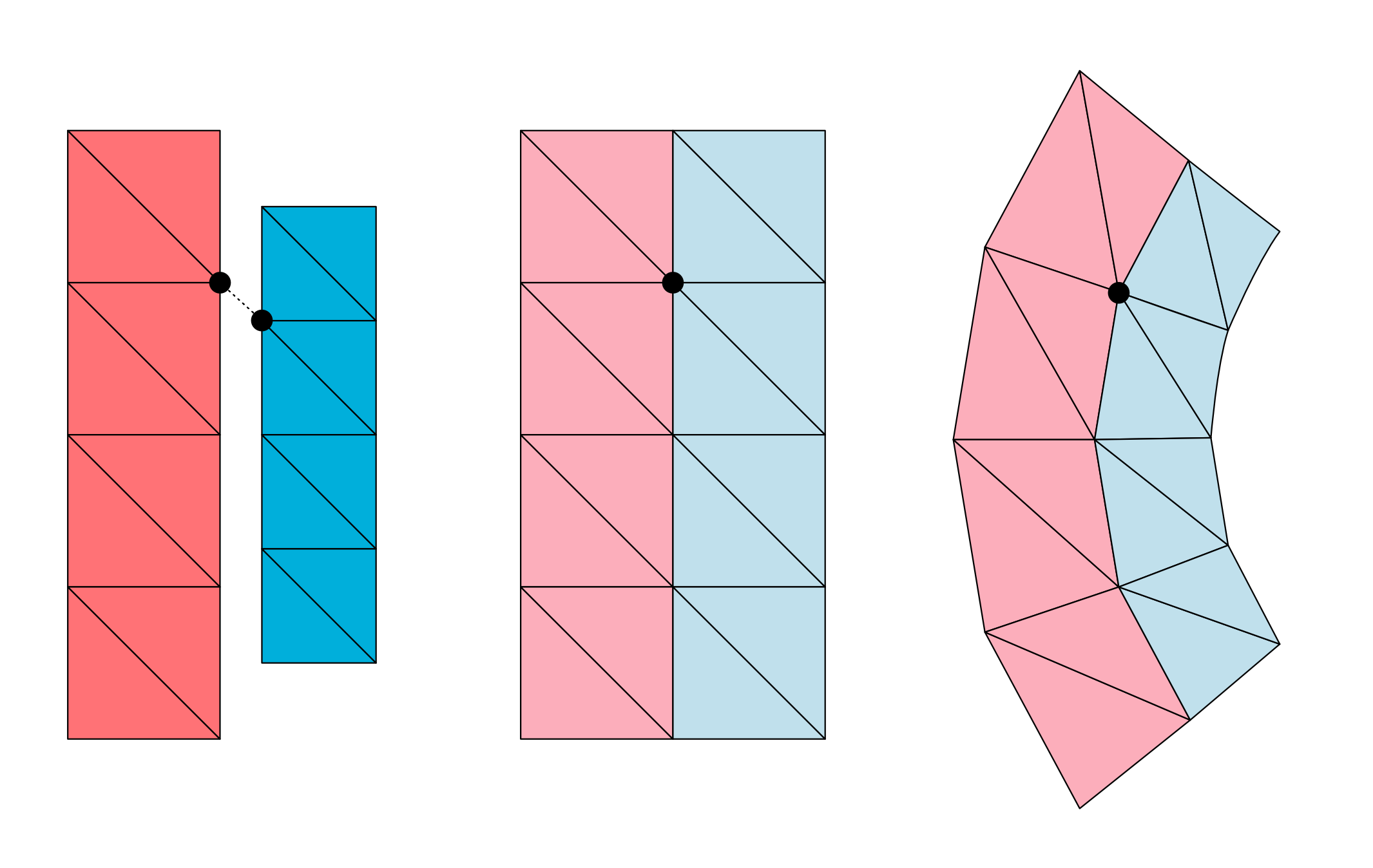
Figure 10 2D illustration of a volume deformable. The rest shape on the left has two disconnected parts with differently sized tetrahedra. For that reason, the mesh describing the rest shape cannot share the same topology as the simulation mesh shown in the middle - some vertices of the simulation mesh need disjoint vertices in the rest shape. The right hand side shows the simulation after simulation.#
This capability is more important in the case of OmniPhysicsSurfaceDeformableSimAPI, which is meant to be applied to surface meshes to represent cloth and shells. In modeling cloth, it is very common to define the planar rest shape of sections of the 3D mesh in a disjoint fashion in a 2D material a.k.a ‘panel space’. The restShapePoints attribute of OmniPhysicsSurfaceDeformableSimAPI has 3D points, but disjoint sets (w.r.t restTriVtxIndices) of these points can be coplanar to support planar rest shape descriptions from panel-based creation tools. Furthermore, this representation allows the description of the planar rest shape that should be compatible with models for 3D shells.
Cloth/Shells based on triangular meshes also require the definition of the rest dihedral angle for the interior edges of the mesh. Using the mesh of cloth pants as an example, a pleat along a consecutive edge run down the front of each leg may be described. Besides increasing the bendStiffness for these edges, the restBendAngles for these edges could be set to something like 75 degrees. The assignment of restBendAngles is specified via restAdjTriPairs, pairs of adjacent triangles the dihedral bend angles refer to.
The rest dihedral bend angles that are not explicitly specified are implicitly defined in two selectable ways. The attribute restBendAnglesDefault can be set to either flatDefault or restShapeDefault. The former implies rest dihedral angles of zero degrees, which is useful for simulating cloth, for example. The latter implies rest angles based on the normals of the triangles, as defined by the rest shape points. This method is useful for simulating uneven 3D shells.
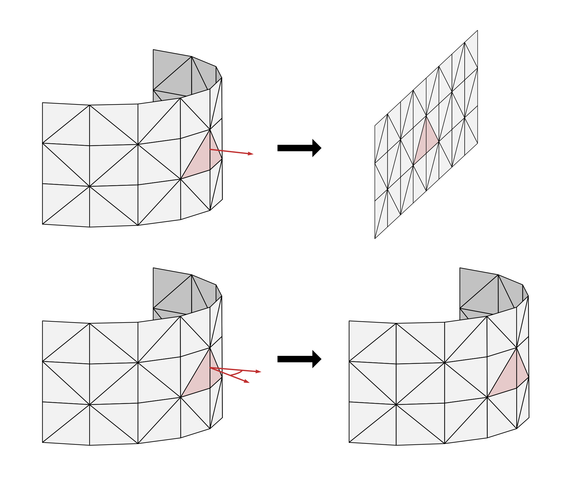
Figure 11 Illustration for the effect of restBendAnglesDefault. Using flatDefault, i.e. assuming dihedral angles of zero, results in simulation mesh settling into a flat shape (top), while using restShapeDefault results in simulation mesh settling into the shape that corresponds to the dihedral angles given by the triangle normals of the rest shape (bottom).#
In defining rest dihedral bend angles, the adjacency is determined by the topology provided by the simulation UsdGeom.Mesh’s faceVertexIndices, rather than the rest shape’s restTriVtxIndices, because the rest shape topology may describe disjoint sets of triangles.
Collision Meshes#
Defining colliders for a deformable body works analogously to rigid bodies. UsdGeom.PointBased geometries in the deformable body hierarchy can be marked with the UsdPhysics.CollisionAPI, which elects them to participate in collision detection. Deformable body colliders are limited to point-based geometries because they need to be able to follow the deformable body’s deformation. The collider meshes are embedded into the simulation mesh and contact forces/impulses computed against the collider can be converted to constraints against the simulation mesh in the simulator. Embedding is supported through the OmniPhysicsDeformablePoseAPI, see section Geometry Embeddings.
Here is an example of a single mesh volume deformable body:
def GeomTetMesh "volumeDeformable" (
    prepend apiSchemas = [
        "OmniPhysicsDeformableBodyAPI",
        "OmniPhysicsVolumeDeformableSimAPI",
        "UsdPhysicsCollisionAPI"
    ]
) { ... }
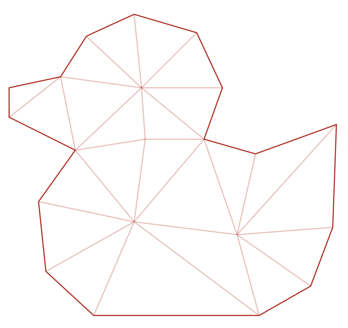
Figure 12 2D illustration of single mesh volume deformable. The tetrahedral mesh surface is used for collision detection.#
And here is an example of a volume deformable body using a specialized simulation mesh with hexahedral structure:
def GeomXform "volumeDeformable" (
    prepend apiSchemas = ["OmniPhysicsDeformableBodyAPI"]
)
{
    def GeomTetMesh "simulationHexMesh" (
        prepend apiSchemas = ["OmniPhysicsVolumeDeformableSimAPI"]
    ) { ... }
    def GeomMesh "collisionMesh" (
        prepend apiSchemas = ["UsdPhysicsCollisionAPI"]
    ) { ... }
    ...
}
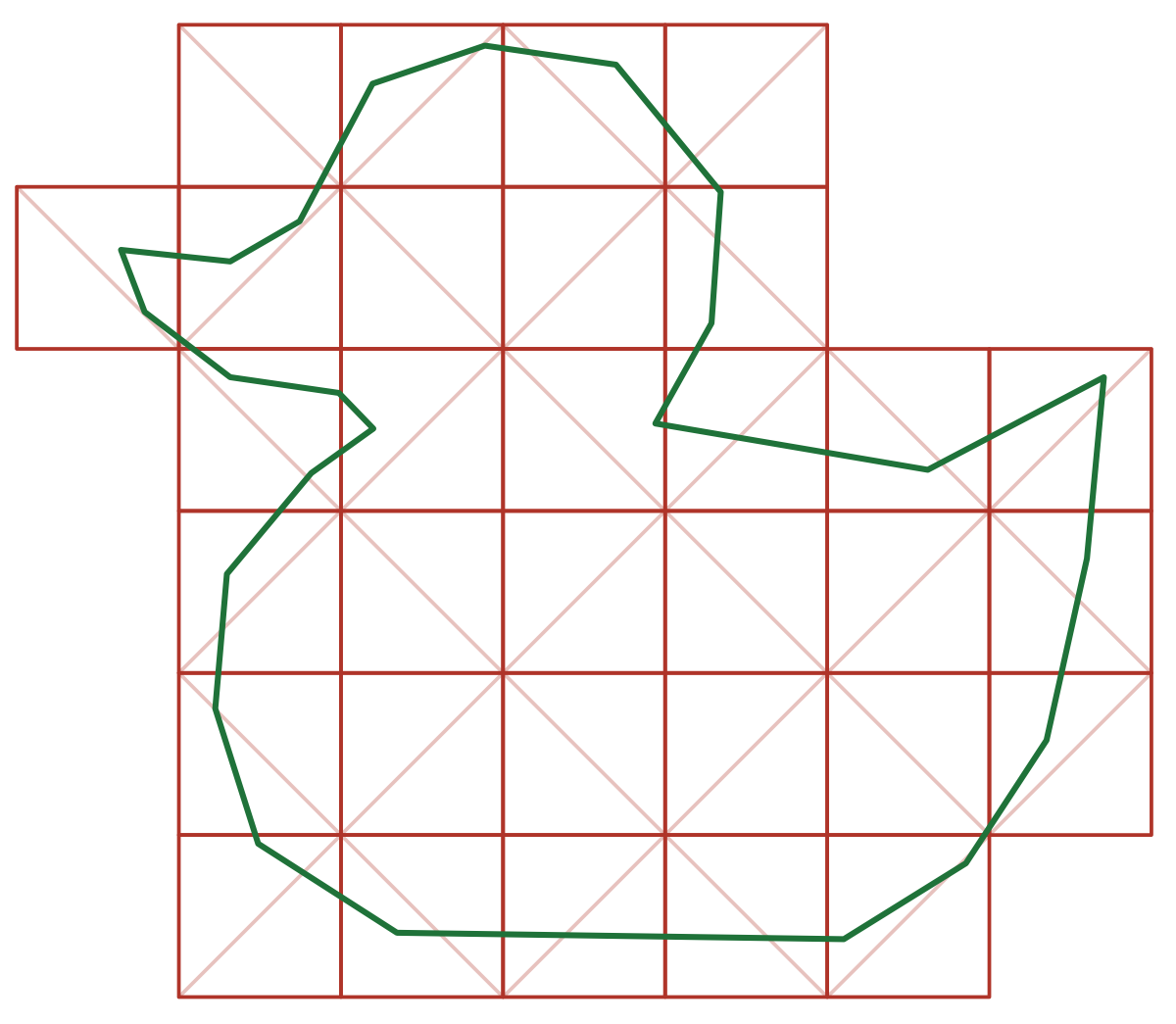
Figure 13 2D illustration of deformable body with a simulation mesh, here a tetrahedral mesh with hexahedral structure (red) and a separate collision mesh (green).#
And another example for a surface deformable configured for collision detection using point samples:
def GeomXform "surfaceDeformable" (
    prepend apiSchemas = ["OmniPhysicsDeformableBodyAPI"]
)
{
    def GeomMesh "simulationMesh" (
        prepend apiSchemas = ["OmniPhysicsSurfaceDeformableSimAPI"]
    ) { ... }
    def GeomPoints "collisionGeom" (
        prepend apiSchemas = ["UsdPhysicsCollisionAPI"]
    ) { ... }
    ...
}
Figure 14 Surface deformable body with triangle simulation mesh (red) and point sampling for collision detection (green).#
Group and pair filters as defined with UsdPhysics.CollisionGroup and UsdPhysics.FilteredPairsAPI directly apply to deformable body colliders.
UsdPhysics.MassAPI, as supported for rigid body colliders will be ignored. Instead, non-uniform mass distributions across the simulation mesh can be expressed using OmniPhysicsDeformableMaterialAPI bindings affecting the simulation mesh, see Assigning Materials for more details.
Even though meshes are explicitly tagged to participate in collision detection, the implementation is still free to choose whether to create an intermediate representation for the collision mesh or meshes it uses internally. However, such an implicit approach has the disadvantage that the per-element collision filtering covered in the section Element Collision Filtering can’t be applied. The OmniPhysicsElementCollisionFilter relies on explicit representation for deformable collision meshes in USD.
Graphics Meshes#
It is often possible and desirable for deformation to be simulated at a lower discretization than that used for rendering. For example, a very detailed UsdGeom.Mesh of a car tire may be used to capture all the geometric details of the treads carved into the running surface, made up of tens of thousands of triangles, but an approximate simulation of the stiff rubber material can be done using a volumetric mesh of less than a thousand elements. The simulation operates by deforming the volumetric mesh in response to gravity and collisions, and then deforming the graphics mesh by maintaining its embedding in the simulation mesh. Embedding is supported through the OmniPhysicsDeformablePoseAPI, see section Geometry Embeddings.
Meshes that are exclusively used for graphics are not particularly tagged but are rather identified by being hierarchically beneath the OmniPhysicsDeformableBodyAPI prim and neither being marked with a simulation API nor with a collision API.
An example based on the tire setup is illustrated below:
def GeomXform "tire" (
    prepend apiSchemas = ["OmniPhysicsDeformableBodyAPI"]
)
{
    def GeomTetMesh "simulationMesh" (
        prepend apiSchemas = [ "OmniPhysicsVolumeDeformableSimAPI" ]
    ) { ... }
    def GeomMesh "collisionMesh" {
        prepend apiSchemas = [ "UsdPhysicsCollisionAPI" ]
    ) { ... }
    def GeomMesh "graphicsMesh" (
        # Deformed according to embedding in simulationMesh.
    ) { ... }
    ...
}
For surface deformables, the simulation mesh is of type UsdGeom.Mesh as well, but can still be discretized differently:
def GeomXform "surfaceDeformable" (
    prepend apiSchemas = ["OmniPhysicsDeformableBodyAPI"]
)
{
    def GeomMesh "simulationMesh" (
        prepend apiSchemas = [
            "OmniPhysicsSurfaceDeformableSimAPI",
            "UsdPhysicsCollisionAPI"
        ]
    ) { ... }
    def GeomMesh "graphicsMesh" (
        # Deformed according to embedding in simulationMesh.
    ) { ... }
    ...
}
Pre-existing graphical assets often consist of multiple graphics meshes, for example, to facilitate easy assignment of graphics materials, and may be organized hierarchically. For example:
def GeomXform "rubberChickenToy" ()
{
    def GeomMesh "body" () { ... }
    def GeomMesh "eyeballs" () { ... }
    def GeomXform "left_leg" () {
        def GeomMesh "left_leg" () { ... }
        ...
    }
    def GeomXform "right_leg" () {
        def GeomMesh "right_leg" () { ... }
        ...
    }
    ...
}
Marking such an asset for rigid body simulation would be relatively easy as follows: apply UsdPhysics.RigidBodyAPI to rubberChickenToy, apply UsdPhysics.CollisionAPI and UsdPhysics.MeshCollisionAPI to all meshes in the subtree. For deformable body simulation, a tool is assumed to apply the OmniPhysicsDeformableBodyAPI to the root, then generate a suitable simulation UsdGeom.TetMesh and OmniPhysicsVolumeDeformableSimAPI from all meshes in the subtree, then, for example, re-use the generated simulation mesh as a collider with UsdPhysics.CollisionAPI:
def GeomXform "rubberChickenToy" (
    prepend apiSchemas = ["OmniPhysicsDeformableBodyAPI"]
)
{
    def GeomMesh "body" () { ... }
    def GeomMesh "eyeballs" () { ... }
    def GeomXform "left_leg" () {
        def GeomMesh "left_leg" () { ... }
        ...
    }
    def GeomXform "right_leg" () {
        def GeomMesh "right_leg" () { ... }
        ...
    }
    def GeomTetMesh "simulationMesh" (
        prepend apiSchemas = [
            "OmniPhysicsVolumeDeformableSimAPI", "UsdPhysicsCollisionAPI"
        ]
    ) { ... }
    ...
}
Alternatively, the tool may generate a separate collision mesh with UsdPhysics.CollisionAPI or apply UsdPhysics.CollisionAPI per graphics mesh in the subtree.
Geometry Embeddings#
Embedding a collision or graphics mesh into a simulation tetrahedral mesh is relatively straightforward using barycentric coordinates. However, for animating detailed clothing, usually extrapolation is required since the graphics mesh points generally lie outside of the piecewise linear simulation mesh. How this extrapolation is defined can vary greatly. The physics schema, therefore, leaves the embedding representation up to the implementation.
The embedding can be defined based on the default poses of both simulation mesh and embedded mesh. When evolving the simulation, the embedding representation typically remains constant, but reconstructing the representation at any given time might come at a loss of accuracy. A specific binding pose can be defined for simulation and embedded meshes by applying a OmniPhysicsDeformablePoseAPI, using the bindPose token within the purposes attribute.
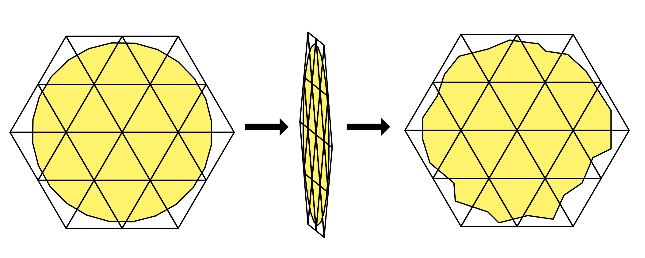
Figure 15 Exaggerated illustration of numerical issues occurring when reconstructing the graphical mesh embedding from the current state of the simulation and graphics mesh:#
class "OmniPhysicsDeformablePoseAPI"
(
    customData = {
        token apiSchemaType = "multipleApply"
        token propertyNamespacePrefix = "deformablePose"
    }
    inherits = </APISchemaBase>
)
{
    uniform token[] omniphysics:purposes()
    point3f[] omniphysics:points()
}
The tire example from above is extended here with a custom OmniPhysicsDeformablePoseAPI that specifies the bindPose purpose:
def GeomXform "tire" (
    prepend apiSchemas = ["OmniPhysicsDeformableBodyAPI"]
)
{
    def GeomTetMesh "simulationMesh" (
        prepend apiSchemas = [
            "OmniPhysicsVolumeDeformableSimAPI",
            "OmniPhysicsDeformablePoseAPI:custom"
        ]
    ) {
        token[] deformablePose:custom:omniphysics:purposes = ["bindPose"]
        point3f[] deformablePose:custom:omniphysics:posePoints = [...]
        ...
    }
    def GeomMesh "collisionMesh" {
        prepend apiSchemas = [
            "UsdPhysicsCollisionAPI",
            "OmniPhysicsDeformablePoseAPI:custom"
        ]
    ) {
        token[] deformablePose:pose:omniphysics:purposes = ["bindPose"]
        point3f[] deformablePose:custom:omniphysics:posePoints = [...]
        ...
    }
    def GeomMesh "graphicsMesh" (
        prepend apiSchemas = [ "OmniPhysicsDeformablePoseAPI:custom" ]
    ) {
        token[] deformablePose:custom:omniphysics:purposes = ["bindPose"]
        point3f[] deformablePose:custom:omniphysics:posePoints = [...]
        ...
    }
    ...
}
Deformable Materials#
Two new material APIs are introduced: OmniPhysicsDeformableMaterialAPI and OmniPhysicsSurfaceDeformableMaterialAPI.
OmniPhysicsDeformableMaterialAPI extends OmniPhysicsBaseMaterialAPI and introduces the important engineering concepts of Young’s Modulus and Poisson’s Ratio as attributes. Young’s Modulus has no default value because its units are dependent on the base mass and distance units used, and different defaults would make sense depending on these units.
OmniPhysicsSurfaceDeformableMaterialAPI extends OmniPhysicsDeformableMaterialAPI with additional properties for thin shells, including thickness and two different stiffness parameters along three different dimensions. These allow a shell to use not the homogenous Young’s Modulus but rather different stiffnesses in the stretch, shear and bend dimensions. These stiffnesses have the same units as Young’s Modulus, and default to zero, implying that the behavior is governed by Young’s Modulus and shell thickness.
It is permitted to apply multiple physics material APIs to a single material. This makes it possible to use the material on both rigid objects and various types of deformable objects.
For example, a general-purpose physics material instance ‘rubberMaterial’ can be defined as a combination of applying UsdPhysics.MaterialAPI (for rigid bodies), OmniPhysicsDeformableMaterialAPI, OmniPhysicsSurfaceDeformableMaterialAPI.
This implies, for example, that friction parameters must remain consistent for rigid and deformable use cases. This can be addressed by creating separate rigidRubber and deformableRubber materials. For details on deformable material assignment, see Assigning Materials.
class "OmniPhysicsBaseMaterialAPI"
(
    inherits = </APISchemaBase>
)
{
    float omniphysics:dynamicFriction = 0.0 ()
    float omniphysics:staticFriction = 0.0 ()
    float omniphysics:density = 0.0 ()
}
class "OmniPhysicsDeformableMaterialAPI"
(
    inherits = </APISchemaBase>
    prepend apiSchemas = ["OmniPhysicsBaseMaterialAPI"]
)
{
    float omniphysics:youngsModulus = 0.0 ()
    float omniphysics:poissonsRatio = 0.25 ()
}
class "OmniPhysicsSurfaceDeformableMaterialAPI"
(
    inherits = </APISchemaBase>
    prepend apiSchemas = ["OmniPhysicsDeformableMaterialAPI"]
)
{
    float omniphysics:surfaceThickness = 0.0 ()
    float omniphysics:surfaceStretchStiffness = 0.0 ()
    float omniphysics:surfaceShearStiffness = 0.0 ()
    float omniphysics:surfaceBendStiffness = 0.0 ()
}
Assigning Materials#
The assignment of deformable materials follows the same principles as the assignment of rigid body materials. Physics materials are bound in the same way as graphics materials using the UsdShade.MaterialBindingAPI, either with no purpose qualifier or with a specific physics purpose. In the case of deformable materials two kinds of primitives can be affected:
Simulation meshes, tagged with a deformable simulation API, are affected by ‘dynamic’ properties:
Density
Young’s modulus
Poisson’s ratio
Various stiffness parameter
Collision meshes, tagged with the collision API, are affected by ‘surface’ properties:
Dynamic friction
Static friction
Properties are by default percolated down the object tree to the simulation mesh and collision meshes. Additionally, materials can be bound to UsdGeom.Subset prims of these meshes. Simulator implementations can use this feature, if they support sub-mesh element material assignments. For example, the non-uniform density of a volume deformable body could be inferred by reading the material densities of the simulation mesh’s UsdGeom.Subset prims with tetrahedron element type.
Deformable material densities are superseded by OmniPhysicsDeformableBodyAPI:mass, correspondingly to how rigid body material densities are superseded by PhysicsMassAPI:mass. The specific approach to how masses are computed from the densities and geometries are left to the implementation.
Example showing how to use UsdGeom.Subset prims in the previous rubber chicken toy setup to specify multi material behavior:
def ShadeMaterial "softMat" (
    prepend apiSchemas = [ "OmniPhysicsDeformableMaterialAPI" ]
) { ... }

def ShadeMaterial "hardMat" (
    prepend apiSchemas = [ "OmniPhysicsDeformableMaterialAPI" ]
) { ... }

def GeomXform "rubberChickenToy" (
    prepend apiSchemas = ["OmniPhysicsDeformableBodyAPI"]
)
{
    # by default the soft material is used
    rel material:binding:physics = </softMat> (
        bindMaterialAs = "weakerThanDescendants"
    )
    def GeomMesh "body" () { ... }
    def GeomMesh "eyeballs" () { ... }
    def GeomXform "left_leg" () {
        def GeomMesh "left_leg" () { ... }
        ...
    }
    def GeomXform "right_leg" () {
        def GeomMesh "right_leg" () { ... }
        ...
    }
    def GeomTetMesh "simulationMesh" (
        prepend apiSchemas = [
            "OmniPhysicsVolumeDeformableSimAPI", "UsdPhysicsCollisionAPI"
        ]
    ) {
        # individual tetrahedra can use the hard material
        def GeomSubset "subsetHard" (
            prepend apiSchemas = ["MaterialBindingAPI"]
        )
        {
            uniform token elementType = "tetrahedron"
            uniform token familyName = "materialBind"
            int[] indices = [...]
            rel material:binding = </hardMat> (
                bindMaterialAs = "weakerThanDescendants"
            )
        }
        ...
    }
    ...
}
Although the deformable schema does not define the effects of deformable materials on graphics meshes, bindings to graphics meshes may still prove useful. Tools that generate simulation and collision meshes can use these bindings, including bindings on UsdGeom.Subset primitives, as hints for how to apply multiple materials to the generated simulation and collision meshes.
Kinematic Deformables#
USD physics permits a rigid body to be set to a kinematic state, and have its motion be hand-animated, such that an instantaneous velocity based on the movement can be inferred. Such a body will act as an infinitely massive physics object and can push other dynamic physics objects out of the way. The same feature is also desirable for deformables. Kinematic deformables are marked using their kinematicEnabled attribute. The pose of the kinematic deformable body can be animated by setting the points of the simulation mesh.
Attachments#
Attachments between two deformable bodies or a deformable body and an xformable (e.g., a rigid body or static collider) are supported. Attachment relationships and index attribute lists pertain to the simulation meshes, not the associated collision or graphics geometry of a deformable.
Self-attachment is also allowed, provided the supplied indices are suitably disjoint. In other words, don’t attach a vertex to a face that it belongs to or a vertex to itself. Attachments may be hard or soft. The stiffness attribute specifies the strength of the attachment. A value of inf implies that the simulator should treat the constraint as hard if it is possible. The damping attribute only applies if the constraint isn’t hard.
OmniPhysicsAttachment is the base class for all instantiatable attachment types, similar to how UsdPhysics.Joint is the base class for rigid body joints. It contains the attributes which are common to all attachment types:
attachmentEnabled: Enables/disables the attachment.src0,src1: Specify the source primitives. The concrete attachment types further specify the attachment points relative to these sources.stiffness,dampingSpecify the constitutive properties of the attachment.
class OmniPhysicsAttachment "OmniPhysicsAttachment"
(
    inherits = </Imageable>
)
{
    bool omniphysics:attachmentEnabled = true ()
    rel omniphysics:src0 ()
    rel omniphysics:src1 ()
    float omniphysics:stiffness = inf ()
    float omniphysics:damping = 0.0 ()
}
OmniPhysicsVtxVtxAttachment provides a simple attachment mechanism between two corresponding sets of vertices with the same number of elements. This can be used to support the common case of stitching together panels of cloth to create garments.
class OmniPhysicsVtxVtxAttachment "OmniPhysicsVtxVtxAttachment"
(
    inherits = </OmniPhysicsAttachment>
)
{
    int[] omniphysics:vtxIndicesSrc0()
    int[] omniphysics:vtxIndicesSrc1()
}
OmniPhysicsVtxTriAttachment attaches the vertices of one deformable to the triangular faces of another. Each vertex index in the vtxIndicesSrc0 list must have a corresponding triangle face index in triIndicesSrc1. The list triCoordsSrc1 is used to describe the vertex-triangle binding. The first two entries of the vector3f are the U&V barycentric coordinates with respect to the triangle. The third coordinate is the normal offset:
class OmniPhysicsVtxTriAttachment "OmniPhysicsVtxTriAttachment"
(
    inherits = </OmniPhysicsAttachment>
)
{
    int[] omniphysics:vtxIndicesSrc0()
    int[] omniphysics:triIndicesSrc1()
    vector3f[] omniphysics:triCoordsSrc1()
}
OmniPhysicsVtxTetAttachment is similar but is meant to attach vertices to tetrahedra of deformables. Instead of triCoordsSrc1, it has tetIndicesSrc1 which are simply the three barycentric coordinates of the vertices with respect to the tetrahedra. The fourth coordinate can be determined by the three provided. No restriction is placed on the vertex location with respect to a tetrahedron. It can be inside or outside:
class OmniPhysicsVtxTetAttachment "OmniPhysicsVtxTetAttachment"
(
    inherits = </OmniPhysicsAttachment>
)
{
    int[] omniphysics:vtxIndicesSrc0()
    int[] omniphysics:tetIndicesSrc1()
    vector3f[] omniphysics:tetCoordsSrc1()
}
OmniPhysicsVtxXformAttachment attaches the vertices of one deformable to an arbitrary xformable coordinate frame with support for spatial offsets defined within the referenced coordinate frame. If the referenced xformable is a rigid body or a prim in the subtree of a rigid body, then the attachment is expected to be treated by the solver as a two-way constraint:
class OmniPhysicsVtxXformAttachment "OmniPhysicsVtxXformAttachment"
(
    inherits = </OmniPhysicsAttachment>
)
{
    int[] omniphysics:vtxIndicesSrc0()
    point3f[] omniphysics:localPositionsSrc1()
}
OmniPhysicsTetXformAttachment attaches the tetrahedra of one deformable to an arbitrary xformable coordinate frame. Instead of attaching a tetrahedon vertex, it is sometimes necessary to attach an arbitrary point within the tetrahedron, for example to embedd a rigid body within a volume deformable. There may be no vertices located inside the rigid’s shape, or the ones that are may be insufficient:
class OmniPhysicsTetXformAttachment "OmniPhysicsTetXformAttachment"
(
    inherits = </OmniPhysicsAttachment>
)
{
    int[] omniphysics:tetIndicesSrc0()
    vector3f[] omniphysics:tetCoordsSrc0()
    point3f[] omniphysics:localPositionsSrc1()
}
OmniPhysicsTriTriAttachment provides a way to attach an arbitrary point within a triangle to another triangle, similarly to how OmniPhysicsVtxTriAttachment defines an attachment of a vertex to a triangle:
class OmniPhysicsTriTriAttachment "OmniPhysicsTriTriAttachment"
(
    inherits = </OmniPhysicsAttachment>
)
{
    int[] omniphysics:triIndicesSrc0()
    vector3f[] omniphysics:triCoordsSrc0()
    int[] omniphysics:triIndicesSrc1()
    vector3f[] omniphysics:triCoordsSrc1()
}
Element Collision Filtering#
While UsdPhysics.CollisionGroup and UsdPhysics.FilteredPairsAPI allow for primitive-level collision filtering, which is also supported for deformable bodies, OmniPhysicsElementCollisionFilter supports finer-grained filtering. The element-based filters support collision filtering between two deformable colliders and between deformable colliders and rigid body/static colliders. In the latter case, rigid body and static colliders are always filtered as a whole:
class OmniPhysicsElementCollisionFilter "OmniPhysicsElementCollisionFilter"
(
    inherits = </Imageable>
)
{
    bool omniphysics:filterEnabled = true ()
    rel omniphysics:src0 ()
    rel omniphysics:src1 ()
    uint[] omniphysics:groupElemCounts0()
    uint[] omniphysics:groupElemCounts1()
    uint[] omniphysics:groupElemIndices0()
    uint[] omniphysics:groupElemIndices1()
}
The filtering always takes place at the level of the constituent elements of the deformable collision meshes they refer to:
- Triangles for UsdGeom.Mesh
- Surface triangles for UsdGeom.TetMesh
Which elements are filtered against which, is specified using pairs of element groups. Each pair of groups defines the elements of both colliders that should not collide with each other. E.g.: triangles [4, 5, 6] of one collider mesh are each not colliding against any triangles [12, 13] of the other collider mesh. The group sizes are specified with groupElemCounts0 and groupElemCounts1, two lists of matching size. The element indices of each group are consecutively stored for all groups in groupElemIndices0 and groupElemIndices1, similarly to how faceVertexCounts specifies the number of vertices per face and faceVertexIndices specifies the vertex indices per face in order.
Two special cases:
A group element count of 0 indicates that all elements of the corresponding collider are to be filtered against the matching group of the other collider.
An empty list of group element counts indicates that all elements of the corresponding collider are filtered against all groups of the other collider. This is also the case in general for rigid body and static colliders, which are always filtered as a whole.
Example - two groups each:
groupElemCounts0 = [2, 1], groupElemIndices0 = [3, 4, 6]
groupElemCounts1 = [2, 3], groupElemIndices1 = [9, 7, 2, 5, 6]
reads:
element 3 and 4 of src0 are filtered against element 9 and 7 of src1,
element 6 of src0 is filtered against element 2, 5 and 6 of src1
Example - pairwise:
groupElemCounts0 = [1, 1], groupElemIndices0 = [3, 4]
groupElemCounts1 = [1, 1], groupElemIndices1 = [9, 7]
reads:
element 3 of src0 is filtered against element 9 of src1,
element 4 of src0 is filtered against element 7 of src1
Example - mixed:
groupElemCounts0 = [3, 2], groupElemIndices0 = [6, 7, 8, 15, 16]
groupElemCounts1 = [0, 1], groupElemIndices1 = [33]
reads:
element 6, 7 and 8 of src0 are filtered against all elements of src1
element 15 and 16 of src0 are filtered against element 33 of src1
Example - one group against all:
groupElemCounts0 = [3], groupElemIndices0 = [3, 4, 6]
groupElemCounts1 = [0], groupElemIndices1 = []
reads:
element 3, 4 and 6 of src0 are filtered against all elements of src1
Element filtering is needed particularly in the context of attachments where usually collisions need to be suppressed to avoid conflicting constraints.
Element filter relationships and index attribute lists pertain only to prims with UsdPhysics.CollisionAPI.
Not supported is filtering based on tetrahedral elements. It is assumed filtering collisions at the tetrahedral mesh surface is sufficient.