Material Manager#
The Material Manager is an interface that is responsible for containing, compiling and executing generically defined materially based Bidirectional Scattering Distribtion Functions (BSDF). Material name and index combinations are input into the manager along with the details for the main entry shader responsible for performing any sensor processing. Sensor Processing is achieved by the Material Manager encapsulating both the main CUDA kernel hit shader for a given sensor and its corresponding material responses. The main shader is executed and the material responses are resolved by the material ID from the RtxSensorReturn and performs the correct material interactions for the sensor casted ray.
This infrastructure provides a mechanism for supporting internally developed material BSDF kernels and is set for a simple “out of the box” experience for sensor modalities. However, the material behaviors (i.e. BSDFs) and properties can be remapped for extendability of the Material Manager framework.
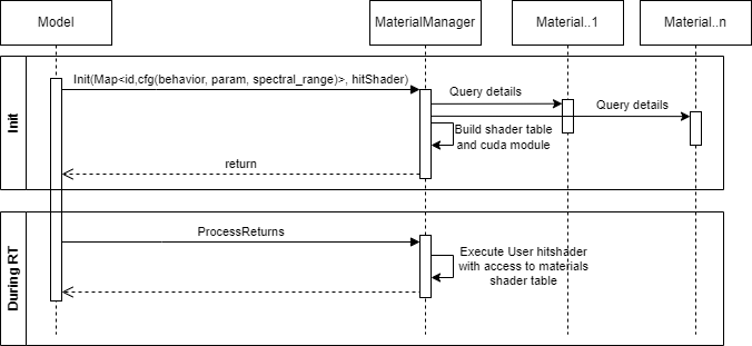
The Material Manager framework is shown here and is described below.
Usage#
The Material Manager has just 3 main points of operation. First is initialization, second is re-initialization, and third is using the manager within the RTX Sensor model (material processing) when batch end is called to process all the hit returns. Despite the Material Manager being an internal plugin, the steps are described here for completeness. Users of the non-visual materials framework can only exercise the re-initializtion of the Material Mangager. All other operational phases are utilized within the sensor modalities (Lidar, Radar, and Ultrasonic). Initialization is performed upon startup but re-initialization can be performed at any time for material properties (e.g. input data) and behaviors (e.g. BSDF functionality).
Initialization#
The Material Manager initialization depends on a valid CUDA device index provided by the RtxSensor Framework. The initialization process will setup the mappings for the Materials to define the behavior and data mapping scheme resolved by the Material Manager to encode a correspondance between the implementation and the input data to process the sensor modality returns from a geometry hit.
Re-initialization#
This re-processes the existing materials, allowing any changes to input data or behaviors. The link here provides a more comprehensive description of how remappings are performed
Material Processing#
Within each trace from RtxSensor, batchBegin and batchEnd calls are made. Since the Material Manager must do
something with the returned hits from the ray-traced scene, material processing is executed from within the batchEnd notification. The following flags
help define specific actions for the BSDF to follow when computing reflections and transmissions.
The enumeration below defines the flags that the BSDF can support. The flags identified here provide the control variables for modifying the BSDF with additional behavior.
enum class NvMatInFlags : uint8_t
{
    CALC_R = 1,
    CALC_T = 2,
    CALC_PHASE_AND_POLARIZED = 4,
    CALC_INTERNAL_TERMS = 8,
};
The NvMatInFlags enumeration defines which components within the BSDF to compute. The BSDF will perform a bitwise OR operation to determine
which additional components to compute. The CALC_R component computes the reflectance along the mirror reflection angle direction. The CALC_T
component computes the transmission component in the direction defined by the input direction and the material properties. The CALC_PHASE_AND_POLARIZED
option instructs the BSDF to compute component-wise transverse electric and transverse magnetic polarized values and phase tracking. It is the
responsibility of the sensor model to define sensor space aperture polarization (aka analyzer) for polarized returns that are phase tracked. Finally
CALC_INTERNAL_TERMS is an option that works in conjunction with paints and coating layering on the base material return. Light can reflect many times
within a layer adding reflection and transmission terms to the base reflection and transmission options selected. This provides an additional level
of accuracy when paint and coatings are applied to a base material layer. These options are implemented in the current NVIDIA-based BSDF
functionality.
struct NvMatRayProps
{
    float3 vector;
};
The NvMatRayProps structures are members within the input and output structures for the BSDF (shown below) which are filled once the reflection and transmission
data is calculated. It stores the reflected or transmitted coefficients from the surface boundary and is returned to the sensor model hit shader for additional
processing.
The input structure for the non-visual materials workflow is the following.
struct NvMatInput
{
    float3 matNormal;
    float3 lookupRayDir;
    float3 hitPoint;
    uint32_t materialId{ 0 };
    float thickness{ 0 };
    curandStateType randomState;
    uint8_t flags{ 0 };
    float3 incRayDir;
    float3 diffuseRefl{ make_float3(-0.5f, -0.5f, -0.5f) };
    float roughness{ 0.f };
    NvMatRayProps* incRayProps;
    uint32_t customPropsSize{ 0 };
    uint32_t preserveMaterialFlags{ 0xff };
    float distPrevHit{ 0 };
    float sourceDivergence{ 0.f };
    float3 vertexNormals[3]{  make_float3(0, 0, 0), make_float3(0, 0, 0), make_float3(0, 0, 0) };
    float3 vertices[3]{ make_float3(0, 0, 0), make_float3(0, 0, 0), make_float3(0, 0, 0) };
};
The NvMatInput structure contains input details required for computing material reflection and transmission information, and its members are described below. Any vector member is
resolved in relative sensor coordinate space.
Member |
Description |
|---|---|
|
The normal of the current hit point from within the hit shader. |
|
An optional member that defines a look direction. If this look direction is a zero vector, then |
|
The location where the ray intersected the scene. |
|
The material index from the intersected geometry that is returned from the RtxSensorReturn. This ID is passed down to the BSDF via the input structure to provide material index information. |
|
The at-normal incidence depth of the primitive that is hit from the ray-traced scene. |
|
For the |
|
A control to identify how reflection or transmission components are computed (see |
|
The direction of the incident ray in sensor space. |
|
An optional parameter that defines the visible material diffuse color from the hit geometry. Provides additional information to the BSDF to use for more advanced processing. |
|
Optional information from the visible material data. The roughness can be used to provide additional variances (i.e. perturbed normals) derived from visible band content modeling. |
|
Allows the vector to define an input starting point. Rather than assuming 1 for the input, it can be in any unit space such that the BSDF behavior can augment for specific return spaces (i.e. unitless reflectance/transmission, Power space, Radiance space, etc). Note that the |
|
Supports the derived aspect of the |
|
Provides a mechanism for filtering the coating and attribute bits encoded in the |
|
Stores the previous hit distance for accumulating distances where continuation rays can be cast from previous ray hit point. |
|
An optional variable to define how the source radiation diverges. This can be important for the sensor model since the radiometry in any BSDF may need to account for sufficiently diverging source illumination. |
|
Optional data that can be used within the BSDF to compute the curvature and augment the output divergence. This can be important for continuation rays where follow on hit points cause the beam to diverge more or less than it was initially. This is utilized in the radiometric computations for reflections and transmissions from the light matter interactions. |
The NVIDIA sensor models can leverage additional data for added functionality within the BSDF. This includes the NvMatInput for diffuseRefl and roughness parameters
that will be filled in by the rtxSensor for the model to pass to the BSDF. If the flags for additional return information and/or reflectance
information are set, the corresponding RtxSensorData bits will be active and will return additional data in the RtxSensorReturn structure.
// result is a rtx::rtxsensor::RtxSensorRequirements* type coming from the rtxSensor call to getModelRequirements
result->returnDataConfig |= rtx::rtxsensor::RtxSensorReturnData::RTXSENSOR_RETURN_MATERIAL_REFLECTANCE;
result->returnDataConfig |= rtx::rtxsensor::RtxSensorReturnData::RTXSENSOR_RETURN_MATERIAL_ADDITIONAL;
If not set, the RtxSensorReturn struct that stores these values will be nullptr.
The following structure defines the output structure that the BSDF fills for the model to consume.
struct NvMatOutput
{
    float3 exitPoint;
    float distThroughCurMat{ 0.f };
    uint32_t materialId{ 0 };
    NvMatRayProps* lookupRayProps;
    float3 reflRayDir;
    NvMatRayProps* reflRayProps;
    float3 transRayDir;
    NvMatRayProps* transRayProps;
    float outDivergence{ 0.f };
};
The NvMatOutput structure stores necessary elements for reflection and transmission at a boundary surface, and is comprised of the following members:
Member |
Description |
|---|---|
|
Details where the ray has exited a material in sensor local space. |
|
Holds the length through the material that is transmission angle dependent. |
|
The index from the currently intersected geometry from the traced ray. It is typically the same index as the material index from the |
|
The view direction reflection components. |
|
The reflected ray properties. |
|
The transmitted ray direction, with respect to the normal vector. |
|
The transmitted ray properties, with respect to the normal vector. |
|
The computed divergence based on the |
The vector member in the NvMatRayProps stores the reflection
and transmission data both in polarized and unpolarized form. If the input view vector has zero length, reflRayProps computes the mirror angle
angle reflection components. If the view vector is nonzero, it will determine reflectance data as a function of the view vector.
The outDivergence defaults to the input as a passthrough but if the input structure has vertexNormal and vertices data per the RTXSENSOR_RETURN_MATERIAL_ADDITIONAL option above, the curvature of the surface is computed
and augments the sourceDivergence and is passed to the outDivergence. This is important for details like continuation rays, which need this metric for accounting
for how light can diverge and affect the returned signal computation in the sensor model.