
Camera Intrinsic Calibration#
Any developer building a perception stack or sensor simulation faces the same bootstrapping problem: the camera hardware arrives with a nominal focal length in the datasheet, but real lenses deviate from the ideal pinhole model. Radial barrel or pincushion distortion, off-centre principal points and different horizontal and vertical focal lengths all accumulate into errors that are invisible in a casual test image but become systematic bias the moment you try to measure anything — reprojection residuals, disparity maps, object ranges, or the fidelity of a synthetic dataset.
The standard remedy is intrinsic calibration: photograph a target of known geometry (a flat checkerboard) from multiple viewpoints and let an optimizer fit the camera model to the observed corner positions. The result is a compact parameter set — the 3×3 camera matrix K plus a distortion vector D — that makes the camera numerically consistent with the physical world. Two lens models are common: the pinhole model with polynomial radial and tangential distortion, suited to most automotive and industrial lenses; and the fisheye (Kannala-Brandt) model, which handles the extreme wide-angle projections found in surround-view and ADAS cameras.
Omniverse RTX cameras can carry exactly this parameter set through the dedicated
OpenCV lens-distortion API schemas: OmniLensDistortionOpenCvPinholeAPI and
OmniLensDistortionOpenCvFisheyeAPI. Those schemas store the solved focal lengths,
principal point, image size and distortion coefficients in the USD layer. This means
the gap between the real camera and its digital twin is just a file-write away: calibrate
the physical lens once, export the parameters as a USDA asset, and any simulation built
on that asset inherits the measured optics automatically — no manual transcription of
datasheet values, no empirical tweaking of sliders.
calibrate_camera_to_usd.py
automates that bridge. It uses OpenCV — the industry-standard computer vision
library — to detect checkerboard corners and run the calibration solver, then writes
the results directly into a USD Camera prim that encodes the solved intrinsic
parameters: focal length, principal point and lens distortion. The output drops
directly into an Omniverse RTX simulation without any manual parameter entry.
Prerequisites#
Requires Python 3.8+, opencv-python, numpy, and usd-core. Download
calibrate_camera_to_usd.py
and requirements.txt,
then place both files in a folder named intrinsic_calibration_script.
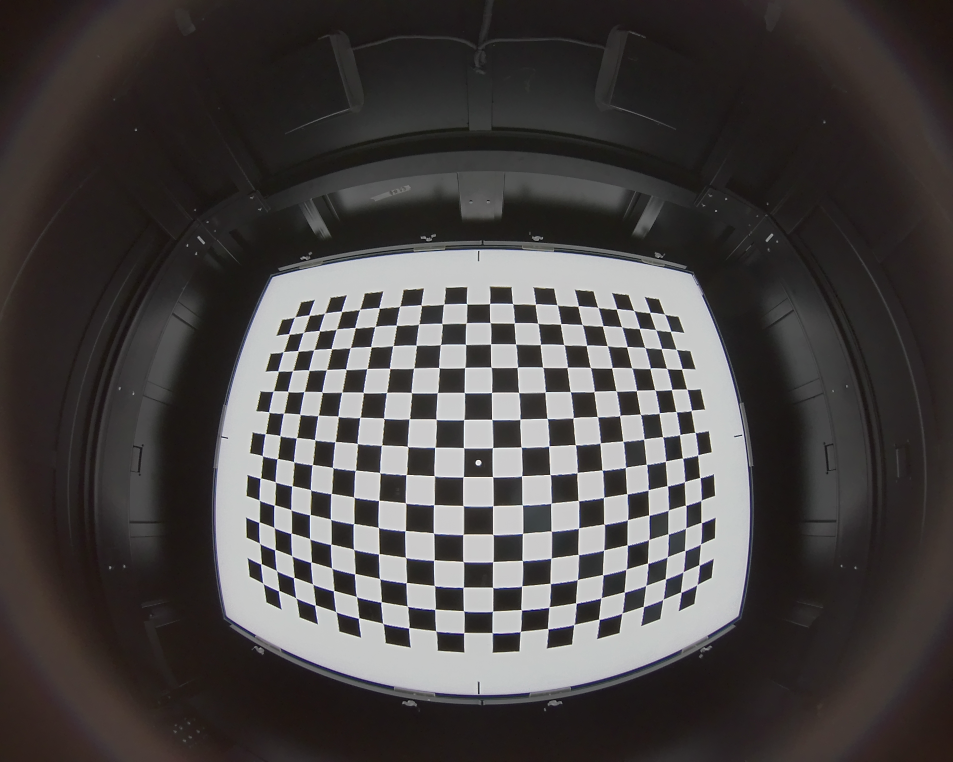
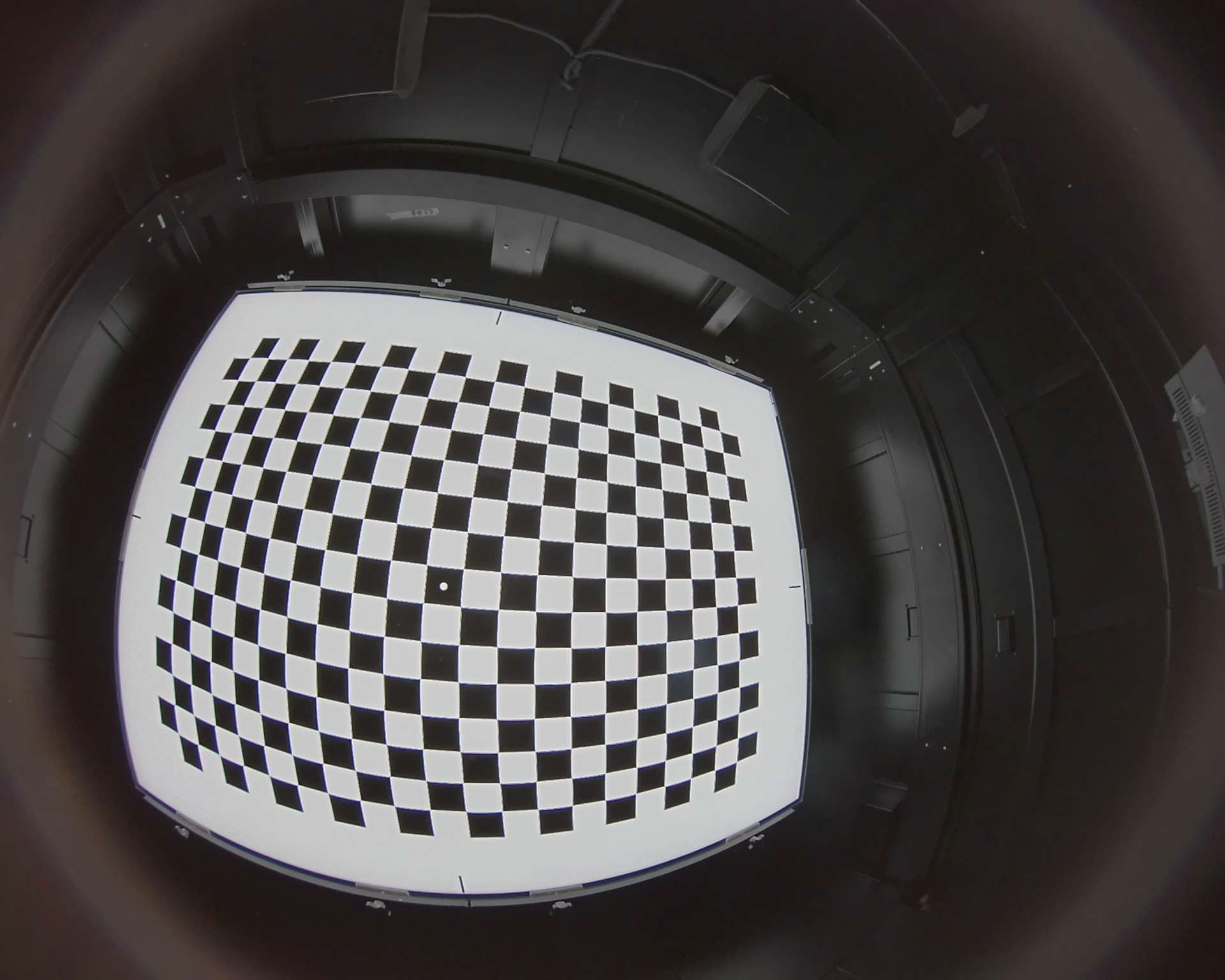
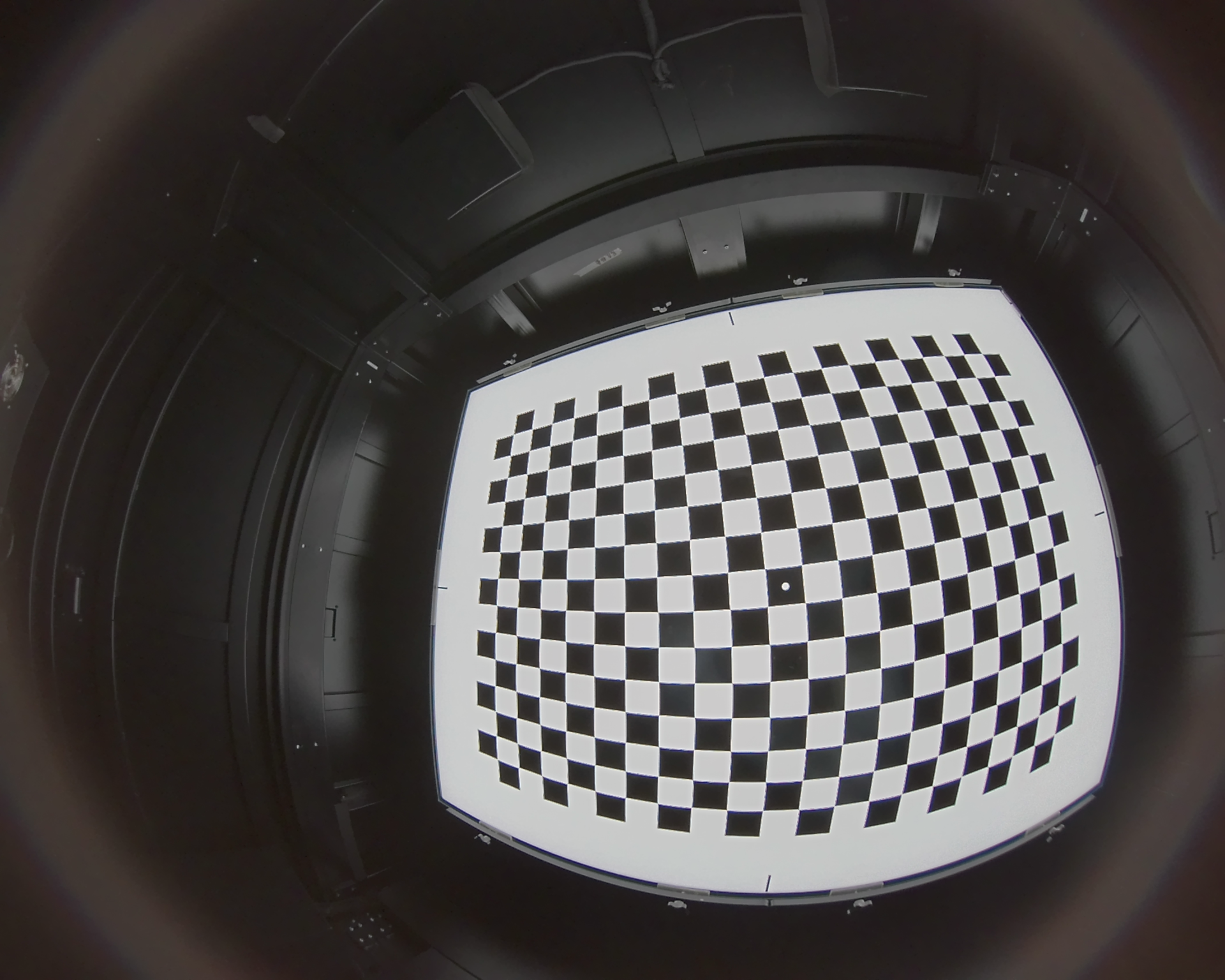
Input images of a checkerboard test surface are needed to run the calibration. Examples images can be used to test the script. Download them to
intrinsic_calibration_script/input_images/:
Internal_reference_calibration_1.png
Internal_reference_calibration_3.png
Internal_reference_calibration_5.png
Internal_reference_calibration_11.png
Internal_reference_calibration_12.png
Internal_reference_calibration_13.png
Internal_reference_calibration_14.png
Internal_reference_calibration_15.png
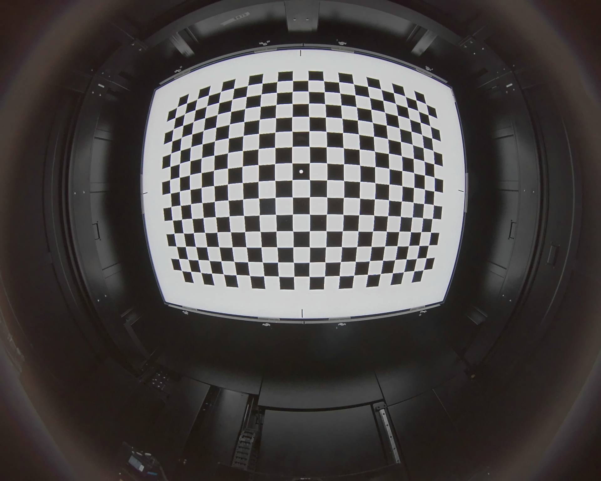
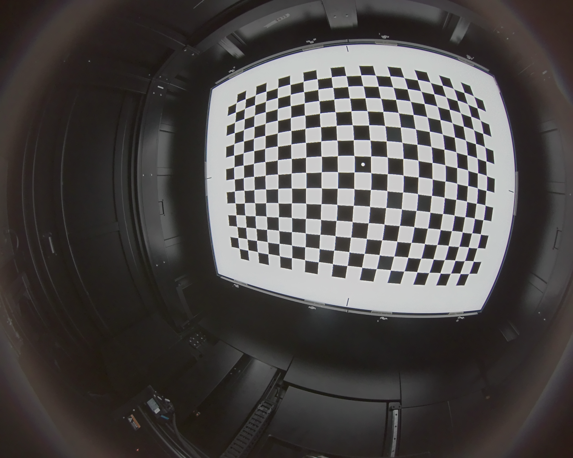
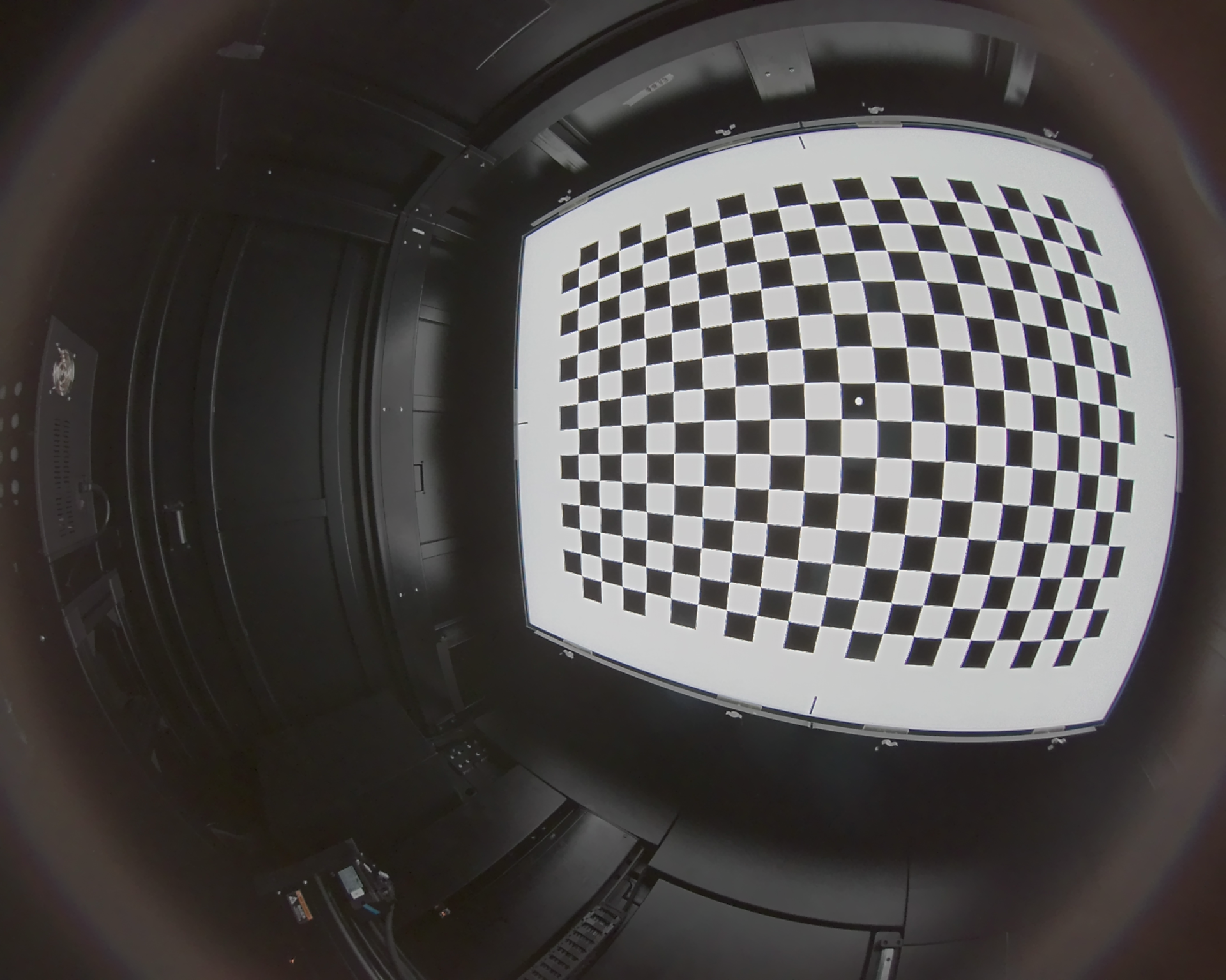
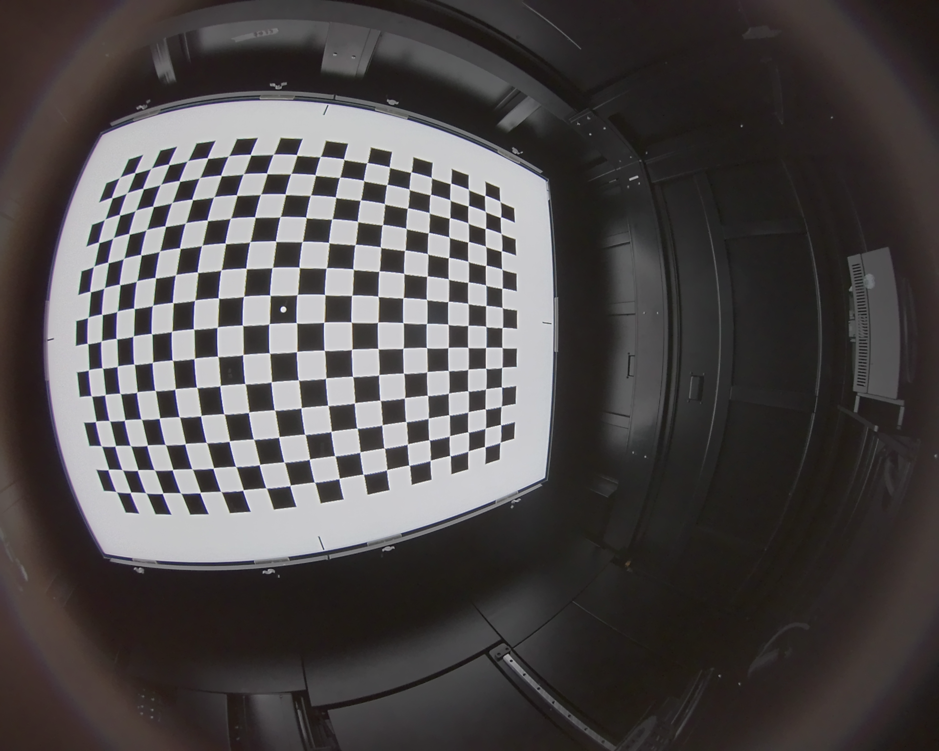
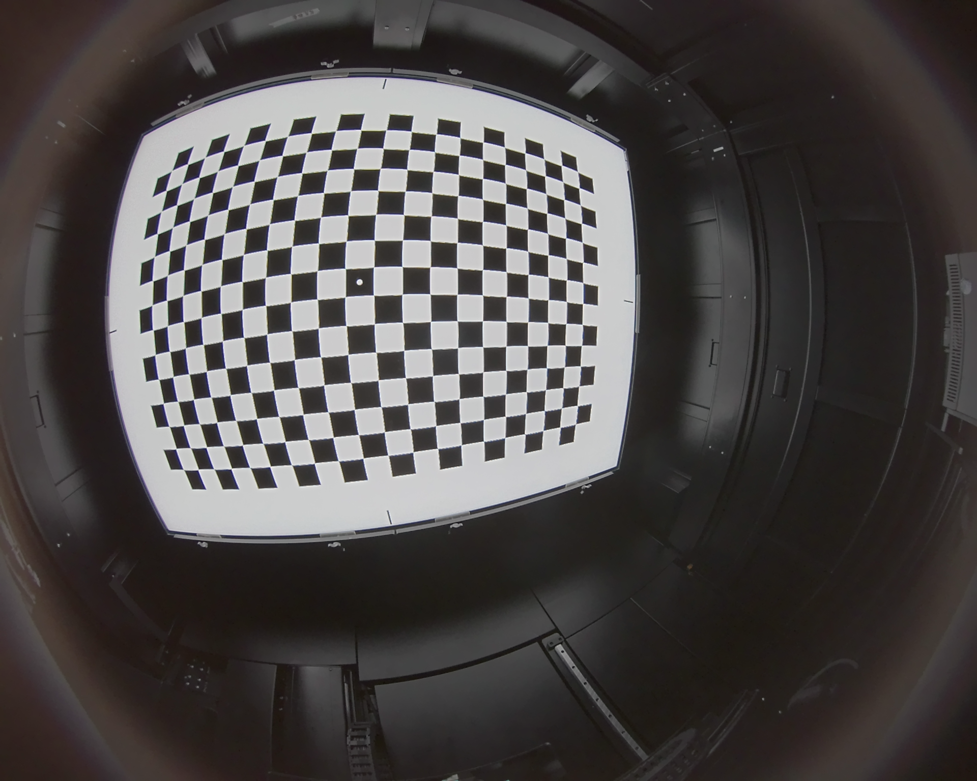
The commands
below assume the script, requirements file, and optional input_images/ folder are
in the intrinsic_calibration_script folder.
Linux:
cd intrinsic_calibration_script
python3 -m venv .venv
.venv/bin/python -m pip install -r requirements.txt
Windows PowerShell:
cd intrinsic_calibration_script
py -3 -m venv .venv
.\.venv\Scripts\python.exe -m pip install -r requirements.txt
If py is not available on Windows, use python in its place.
Usage#
To run the example, place the input images at intrinsic_calibration_script/input_images/. The
script can then be run from the intrinsic_calibration_script/ location as:
Linux:
.venv/bin/python calibrate_camera_to_usd.py \
    --fisheye --pattern 20x14 \
    --output-usd ./_out/calibrated_camera.usda
Windows PowerShell:
.\.venv\Scripts\python.exe .\calibrate_camera_to_usd.py `
    --fisheye --pattern 20x14 `
    --output-usd .\_out\calibrated_camera.usda
Point --images at your own folder to calibrate a different camera. Key options:
Flag |
Description |
|---|---|
|
Folder of checkerboard photos (default |
|
Use the 4-coeff Kannala-Brandt fisheye model |
|
Pinhole only: solve the 8-coeff rational model (k1..k6) |
|
Inner-corner grid, e.g. |
|
Output USDA path (default |
Script Overview#
The script processes images in three main steps, the first being to detect the checkerboard corners.
Step 1 — Detect checkerboard corners#
For each photo, cv2.findChessboardCorners locates the inner-corner grid of the
calibration target. Sub-pixel refinement (cornerSubPix) sharpens the detections
before they are accumulated into the point lists that feed the solver.
found, corners = cv2.findChessboardCorners(gray, pattern, corner_flags)
if not found:
    failed.append(name)
    continue
corners = cv2.cornerSubPix(gray, corners, (5, 5), (-1, -1), subpix)
imgpoints.append(corners.reshape(-1, 1, 2).astype(np.float32))
objpoints.append(objp.reshape(-1, 1, 3).astype(np.float32))
pattern is the number of inner corners (cols, rows) — an N×M square board
has (N-1)×(M-1) inner corners. Pass it with --pattern COLSxROWS.
Step 2 — Solve camera intrinsics#
Once corners are collected from at least three images, OpenCV solves the camera matrix K (focal lengths fx, fy and principal point cx, cy) and the distortion coefficient vector D.
Pinhole (default):
rms, K, D, _, _ = cv2.calibrateCamera(
    objpoints, imgpoints, size, None, None, flags=flags, criteria=crit
)
# D = [k1, k2, p1, p2, k3]   (add --rational for the 8-coeff k1..k6 model)
Fisheye (--fisheye):
rms, K, D = _fisheye_calibrate(objpoints, imgpoints, size)
# D = [k1, k2, k3, k4]   (Kannala-Brandt equidistant polynomial)
The fisheye solver tries several focal-length seeds and keeps the result with the lowest reprojection RMS, which avoids the numerical instability common with wide lenses. A typical RMS below 0.5 pixels indicates a good calibration.
Step 3 — Write the USD camera#
The solved K and D are mapped to the OpenCV lens-distortion attributes and written to a self-contained USDA file:
if is_fisheye:
    schema = "OmniLensDistortionOpenCvFisheyeAPI"
    ns = "omni:lensdistortion:opencvFisheye"
    lens = {
        "fx": fx, "fy": fy, "cx": cx, "cy": cy,
        "k1": coef(0), "k2": coef(1), "k3": coef(2), "k4": coef(3),
    }
else:
    schema = "OmniLensDistortionOpenCvPinholeAPI"
    ns = "omni:lensdistortion:opencvPinhole"
    lens = {
        "fx": fx, "fy": fy, "cx": cx, "cy": cy,
        "k1": coef(0), "k2": coef(1), "p1": coef(2), "p2": coef(3),
        "k3": coef(4), "k4": coef(5), "k5": coef(6), "k6": coef(7),
        "s1": coef(8), "s2": coef(9), "s3": coef(10), "s4": coef(11),
    }
The output is a complete RTX camera asset with the matching OpenCV lens-distortion API schema applied:
def Camera "CalibratedCamera" (
    prepend apiSchemas = ["OmniLensDistortionOpenCvFisheyeAPI"]
)
{
    float omni:lensdistortion:opencvFisheye:fx = 489.92
    float omni:lensdistortion:opencvFisheye:fy = 489.54
    float omni:lensdistortion:opencvFisheye:cx = 965.48
    float omni:lensdistortion:opencvFisheye:cy = 767.20
    int2 omni:lensdistortion:opencvFisheye:imageSize = (1920, 1536)
    float omni:lensdistortion:opencvFisheye:k1 = 0.0746
    float omni:lensdistortion:opencvFisheye:k2 = -0.0260
    float omni:lensdistortion:opencvFisheye:k3 = 0.0094
    float omni:lensdistortion:opencvFisheye:k4 = -0.0014
    custom float calibration:reprojectionRmsPixels = 0.36
    custom string calibration:model = "fisheye (k1..k4)"
    ...
}
Standard UsdGeom.Camera attributes are also set so the prim remains viewable in
plain USD tools. For fisheye cameras, those standard camera values are nominal
viewer-friendly placeholders; RTX uses the lens-distortion schema attributes above
for projection.
Simulation#
Once the USD camera asset is ready, add the calibrated camera parameters to a
Camera prim on your own USD stage. Apply the matching OpenCV lens-distortion API
schema, copy the omni:lensdistortion:opencv* attributes from the generated USDA
asset onto that prim, and render the same calibration poses as the real photos.
The simulated views can be compared directly against the real captures to validate
the calibration.
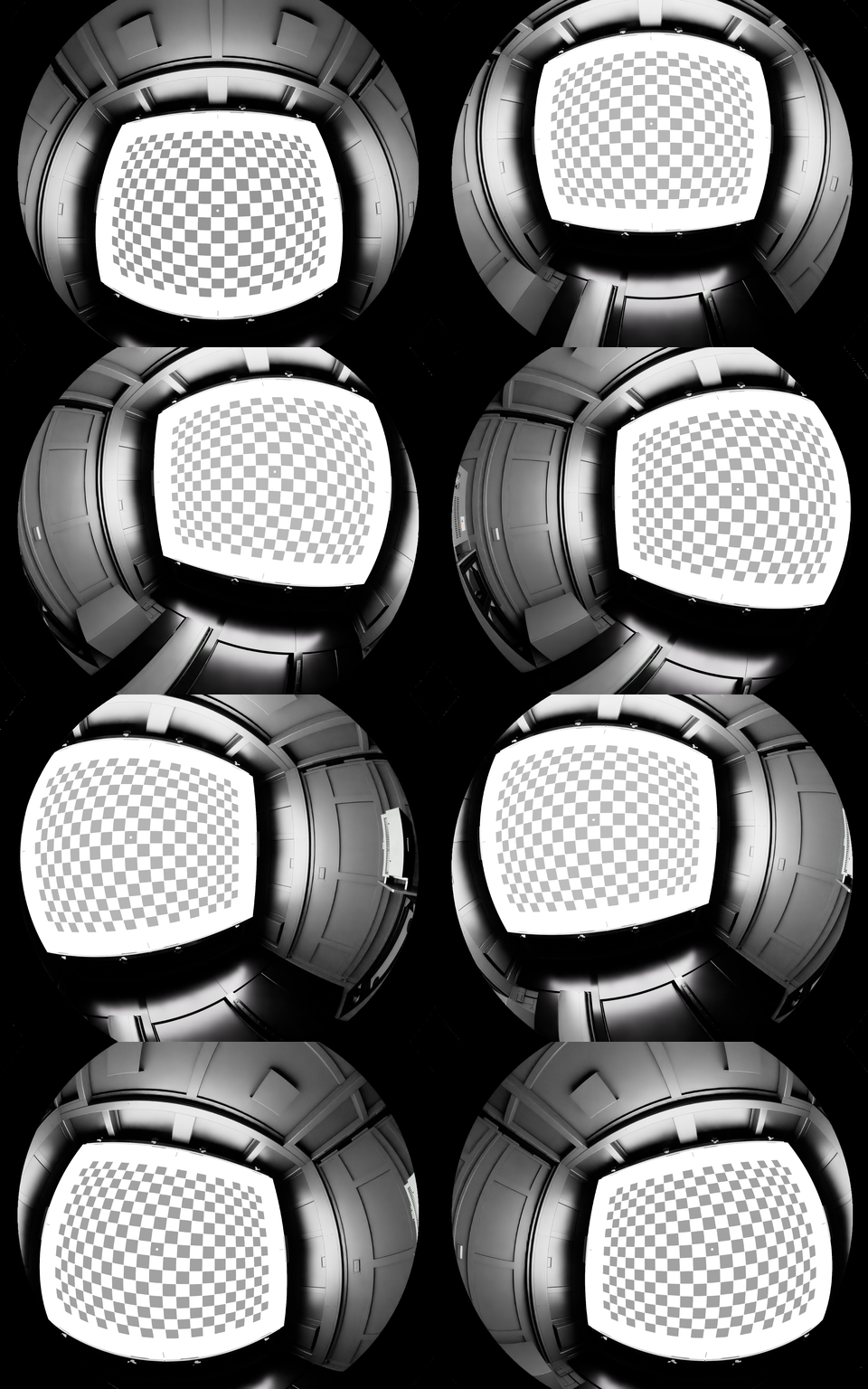
The grid above was rendered in Omniverse Kit, using parameters extracted from sample images. Each tile corresponds to one calibration photo pose; the fisheye distortion in the simulated images matches the distortion visible in the real photos.