Usage
There are two different entry points to import CAD files using the JT Converter.
How to Import and Convert Files
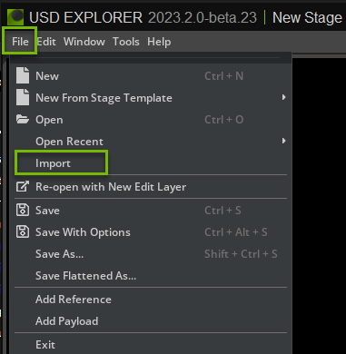
File -> Import
To import a JT file into Omniverse:
Navigate to the top menu and select File > Import
A file dialog will open. Browse to the location of your file, select it, and click Import.

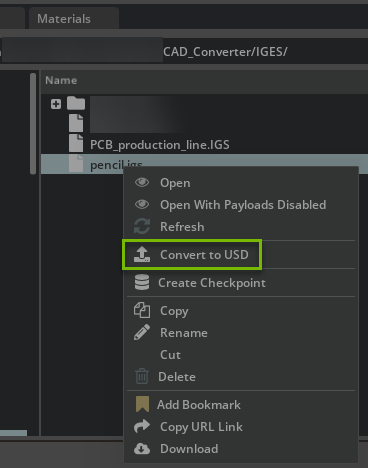
Content Browser -> Convert To USD
To Convert JT files to USD:
If the Content window is not already open. Navigate to the top menu and select Window > Browers > Content.
A Content browser window will open. Browse to the location of your file or files, select them, and right-click, and select Convert to USD in the Context menu.
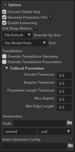
The Converter Options dialog window will appear; modify any options as needed, and click Convert.
Note: You can select more than one file to batch Convert to USD, we recommend turning off Reference in the Current Stage.

Converter Options

Convert Visible Only
If true, skip hidden elements; else, convert hidden elements but set to invisible.
Generate Projection UVs
If UV texture cordinates are missing then this option will use the Scene Optimizer Kit Extension as a post-conversion process to generate texture coordinates for meshes. When this option is enabled, default values are used as described in the Generate Projection UVs section of the Scene Optimizer documentation.
Enable Instancing
This option will determine whether or not instancing will be used in the USD.
Edit Stage Metrics
These options changes the metersPerUnit and/or upAxis of a stage’s active edit target layer by updating the layer’s metadata and applying relevant transformations to attributes that represent world space units so that they reflect the new metersPerUnit/upAxis.
Override Up-Axis
Override the up-axis of the converted USD’s stage to Y-up, Z-up, or default to the converter’s up-axis setting.
Meters Per Unit
Set the meters per unit converted USD’s stage metric. If set to 0.0, the converted USD will retain the meters per unit from conversion.
Override Tessellation Geometry
If true, embedded tessellation geometry will be ignored in favour for explicit tessellation of surface geometry.
Override Tessellation Parameters
If true, embedded tessellation parameters will be ignored in favour for explicit tessellation parameters.
Chordhal Tolerance
The absolute or relative maximal chord height for a polygonal segment with respect to the model.
Angular Tolerance
The maximum angle deviation between subsequent polygonal segments in an approximation of an edge.
Parameter Length
The maximum polygonal segment length.
Max Aspect
The maximum ratio of the longest side of a triangle to the shortest.
Min Edge Length
The minimum length of the edges in the tessellated mesh.
Destination options
Path
Folder for the converted USD. The default location is the exact location, and the CAD file is selected for conversion or selection of a specific destination.
Scene Optimizer Config
(Experimental feature) Provide a path to a saved Scene Optimizer JSON configuration file or a JSON formatted string for executing a predefined optimization process stack. See Scene Optimizer Service documentation for details.
Getting Help
The Developer Community can also ask questions or report issues on Omniverse Developer forums.