Usage#
The user can import CAD files into Omniverse via two workflows: through the File Menu Window or through the Content Window.
How to Import and Convert Files#
File → Import#
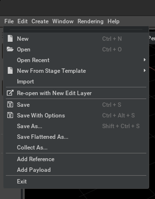
To import a CAD file into Omniverse, choose Import in the File menu.
A file manager window will appear. Select a CAD file for conversion from this window.
Refer to the Converter Options section for more information on conversion settings.
Import through the Content Window#
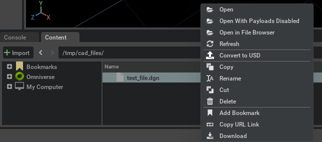
By default, the Content window is located at the bottom of the Omniverse App. To convert a CAD file to USD, select the file in the Content window and choose Convert to USD in the context menu (right-click).
Browse to the location of your file(s), select them, right-click, and select Convert to USD in the context menu.
The Converter Options dialog window will appear. Modify any options as needed and click Convert.
Note: The Content Window tab provides a file browser interface for navigating and managing files. If it is not shown, go to the Menu toolbar, select Window, and then select Content.
Converter Options#
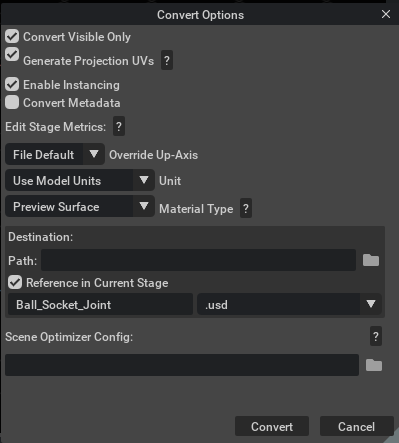
Convert Visible Only#
If enabled, skip hidden elements; otherwise, convert hidden elements but set them to invisible.
Generate Projection UVs#
If UV texture coordinates are missing, this option will use the Scene Optimizer Kit Extension as a post-conversion process to generate texture coordinates for meshes. When this option is enabled, default values are used as described in the Generate Projection UVs section of the Scene Optimizer documentation.
Enable Instancing#
This option determines whether Scenegraph Instancing will be used in the USD.
Convert Metadata#
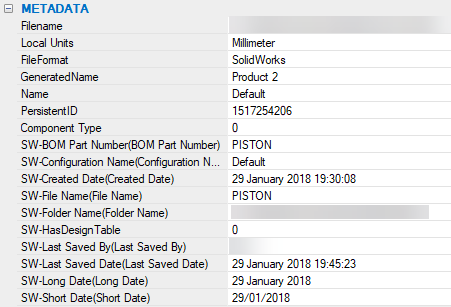
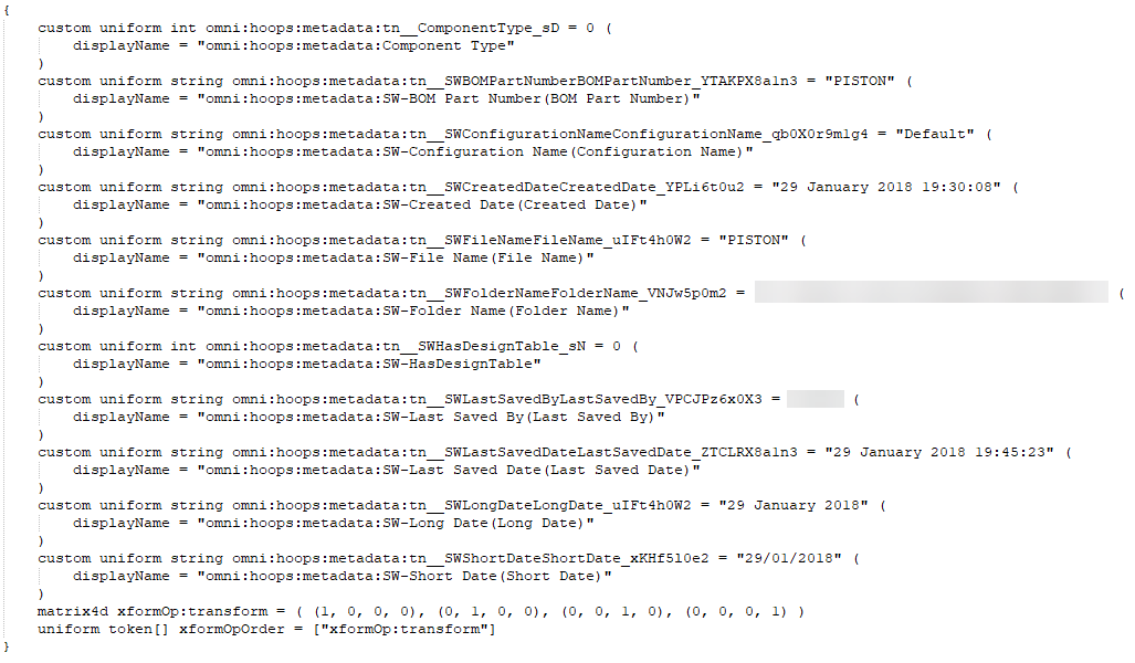
If enabled, metadata including PMI and BIM relationships (applicable only to .ifc models) are imported as USD Attributes or USD Relationships; otherwise, metadata is ignored.
Here is an example of metadata conversion from CAD to USD, where the converted metadata is prefixed with the omni:hoops:metadata namespace. Please consult the comprehensive example in HOOPS Exchange SDK’s Generic Attributes guide to understand how the converter gathers the list of attributes through PRC tree traversal.
Edit Stage Metrics#
These options change the metersPerUnit and/or upAxis of a stage’s active edit target layer by updating the layer’s metadata and applying relevant transformations to attributes that represent world space units so that they reflect the new metersPerUnit/upAxis.
Override Up-Axis#
Override the up-axis of the converted USD’s stage to Y-up, Z-up, or default to the converter’s up-axis setting.
Meters Per Unit#
Set the meters per unit for the converted USD’s stage metric. If set to 0.0, the converted USD will retain the meters per unit from conversion.
Material Selection#
Set the material type for the target renderer:
None: No materials are generated.
USD Preview Surface (default): Compatible with Universal renderer contexts.
OmniPBR (+ USD Preview Surface): Compatible with RTX and Universal renderer contexts.
Tessellation Level#
Tessellation level may be set when converting BREPs to geometry.
The available presets are:
ExtraLow:
ChordHeightRatio=50,AngleToleranceDeg=40Low:
ChordHeightRatio=600,AngleToleranceDeg=40Medium:
ChordHeightRatio=2000,AngleToleranceDeg=40High:
ChordHeightRatio=5000,AngleToleranceDeg=30ExtraHigh:
ChordHeightRatio=10000,AngleToleranceDeg=20
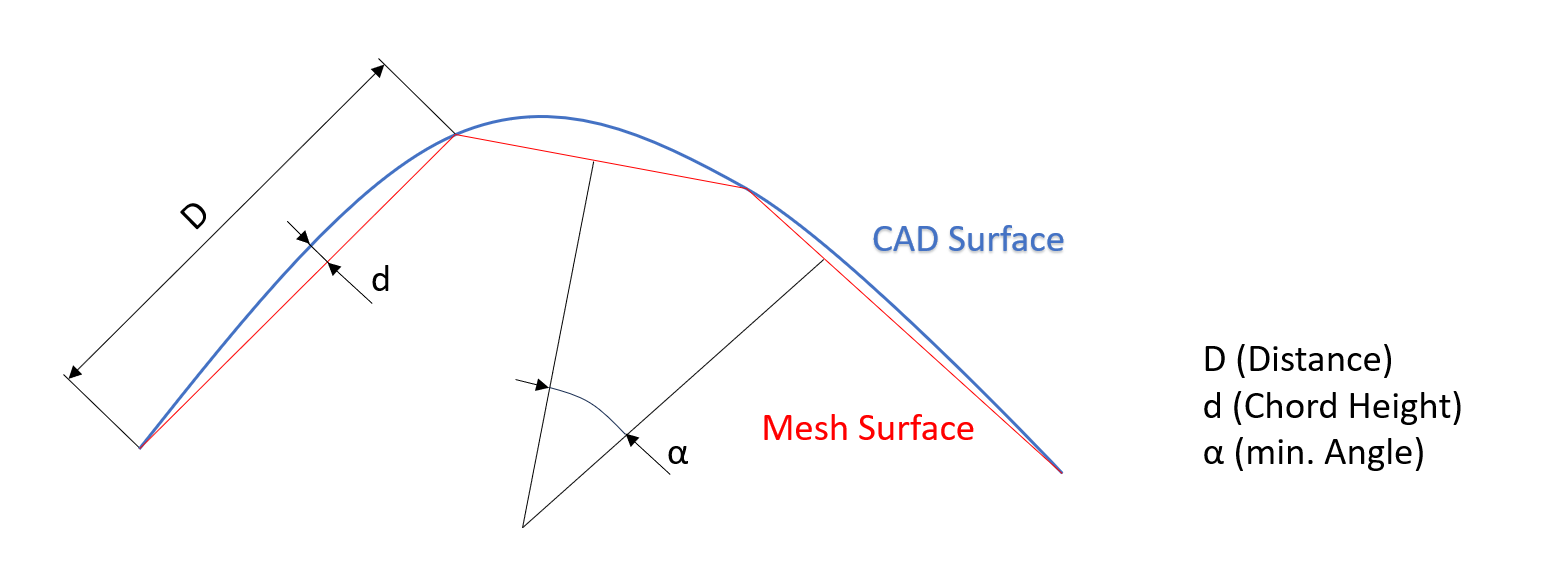
ChordHeightRatio: Specifies the ratio of the diagonal length of the bounding box (defined by D×d) to the chord height.
A value of 50 means that the diagonal of the bounding box is 50 times greater than the chord height.
Values can range from 50 to 10,000. Higher values will generate more accurate tessellation.
AngleToleranceDeg: Specifies the maximum angle between two contiguous tessellation segments describing the curve of a topological edge for every face.
During tessellation, the curve describing the edge of a topological face will be approximated using straight line segments.
AngleToleranceDeg is the maximum angle between two consecutive segments.
Allowable values range from 10 to 40. Lower values will result in greater accuracy.
Destination Options#
The entry points for conversion expose different destination options.
File → Import#
Recommended for importing data into your stage.
Content Browser → Convert to USD#
Destination Options#
Convert to USD is recommended to convert files to external USD files only. You may choose to Reference in Current Stage or not.
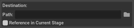
Path: The default location for the converted USD file matches the source file’s location. You may specify an alternative destination if preferred.
Enable Reference in Current Stage to automatically add references in the current stage after conversion. If disabled, the converted USD is saved to the default or specified destination and is not added as a reference in the current stage.
Scene Optimizer Config#
Provide a path to a saved Scene Optimizer JSON configuration file or a JSON formatted string for executing a predefined optimization process stack. See the Scene Optimizer Service documentation for details.
Getting Help#
The Developer Community can also ask questions or report issues on the Omniverse Developer forums