.ogn Best Practices#
These are some recommendations for how to make the contents of your node type description in a .ogn file as effective as possible.
This is a collection of tips that will help you write your node type definition, most commonly found in a .ogn file, to be useful and understandable to the casual user. With hundreds of node types already written and the potential for thousands more it is important that the functionality of each be easily discoverable so that users can avoid rewriting node types that already exist.
Many of these tips are variations of ones you will have heard many times in terms of how to write good code comments and good documentation. That just means it is good information and should be heeded.
Customize Your Node Type#
How to make your node type stand out and be easily recognizable.
“icon”#
You can add a custom icon in the form of a .svg file to represent your node type in the graph editors. The easiest way
is to put it in the file OgnYourNode.svg alongside your OgnYourNode.ogn file. If you do this then you do not need
to add the “icon” keyword to your .ogn file. If you put it in any other location, for example if you want to share
a single icon among multiple nodes, then use the “icon” keyword to specify the location.
The image should be evocative of the function of the node type, yet not overly complex. Here are some examples for a node type that capitalizes a string.
Okay (from category) |
Better (shows result) |
Best (shows function) |
|---|---|---|

|

|

|
“categories”#
Choose a meaningful but targeted list of “categories”. The node type library groups node types using this information so by specifying them you put your node type definition alongside other similar ones. Here’s what you might put in for a node type that multiplies two matrices together.
Okay |
Better |
Best |
|---|---|---|
“math” |
“math:operator” |
[“math:operator”, “math:matrix”] |
“ui_name”#
This is the name that users will see in the interface so make it meaningful! The .ogn will give you a default based on your node type name but you can usually come up with something better if you name it manually. It’s usually better for the name to answer the question “what does it do” rather than “what is it”, as you would prefer the active voice over the passive voice in documentation.
Okay |
Better |
Best |
|---|---|---|
Concatenate |
String Concatenation |
Concatenate Two Strings |
“description”#
This is the core piece of information that your node type definition uses to convey to the user exactly what the node type does, and why they would want to use it.It should fit into a reasonable sized tooltip, and not contain any specialized formatting. That can be reserved for the more detailed documentation you can add by creating a pre/post documentation file (e.g. OgnYourNode.pre.rst and OgnYourNode.post.rst, where you write sections of restructuredText that will appear before and after the automatically generated node type documentation). It should also be read as a complete, grammatically correct sentence.
The text of the description should be detailed enough to get a basic understanding of how the node type works, with attribute-specific details in the respective attribute’s descriptions. You will have to balance the need for precision with the desire for brevity.
Okay |
Better |
Too Far? |
|---|---|---|
Concatenate two strings. |
Output the string that results from concatenating the two inputs strings. |
Creates a single output “Result” that is formed by taking the input string in “Prefix” and appending the input string in “Suffix” to it. For example, inputs of “hello” and “world” will create the output string “helloworld”. |
Attribute Definitions#
The attributes also have user visible facets that should be made clear in order to make your node type more understandable. In particular, the user should be able to look at the attribute names and descriptions and relate them precisely to their function in the node type, knowing what kinds of values to use for inputs and what will appear on the outputs.
“attrName”: “ui_name”#
As with node types the attributes will have a specific name that the user sees and interacts with in interfaces such as the property panels and the graph editor. The UI name should be as descriptive of the attribute as possible without being overly long, cluttering up the interface. In our string concatenation example above the names can substitute for more verbose descriptions.
Good |
Better |
Best |
|---|---|---|
A |
First |
Prefix |
B |
Second |
Suffix |
C |
Result |
Concatenation |
“attrName”: “description”#
As with the node type, the description is the primary source of information for the user on exactly how an attribute will be used and what values inputs can take. It should also be sized and formatted to fit into a tooltip, and read as one or more complete, grammatically correct sentences. The attribute “Prefix” above might be described as follows:
Good |
Better |
Best |
|---|---|---|
First string. |
First half of the output string. |
The first part of the string that will form the concatenated output. |
“attrName”: “type”: “execution”#
Attributes of this type are used for the Action Graph to define and trigger subsections of a graph for evaluation when certain events happen. As all attributes of this type are essentially used for the same thing the wording for their descriptions should be consistent.
The naming conventions are already somewhat consistent for the generic execution attributes, usually “inputs:execIn” for input signals and “outputs:execOut” for output signals. Special purpose node types that contain multiple execution attributes, such as omni.graph.action.Countdown, use a variety of different names that are more indicative of their exact function, as they should.
Normally, the descriptions will tell the user what values are represented by the attributes, however these types of attributes have a limited set of values that are generically described elsewhere so the descriptions in the node type definitions should tell the user when they are triggered.
Commonly Seen |
Better |
|---|---|
Input execution |
Signal to the graph that this node is ready to be evaluated. |
Similarly for output execution attributes the description should tell the user under which circumstances they will be triggered to continue evaluation. Usually it’s just when the node has finished its compute:
Commonly Seen |
Better |
|---|---|
Output execution. |
Signal to the graph that evaluation should continue downstream. |
But for some special purpose nodes there can be more than one that trigger under different circumstances, such as these from the “Countdown” node type.
Good |
Better |
|---|---|
Triggered after duration ticks is finished. |
Output execution signal, triggered after the node has been successfully evaluated a total of “Duration” times after the input “Exec In” signal has been triggered. |
Triggered every ‘period’ ticks |
Output execution signal, triggered every “Period” successful evaluations, stopping after the “Finished” execution pulse is triggered. |
If a node can react to multiple input signals then you should specify what the node will do when each type of signal activates. The graph that reacts to the signals by scheduling execution of the node but it is the node that decides what to do so this difference should be apparent in the description.
Generic |
More Specific |
|---|---|
Signal to the graph that this node is ready for execution. |
Signal to the graph that this node is ready for execution. When the node executes with this signal active it plays the clip from the current frame. |
“attrName”: “type”: “bundle”#
A “bundle” type is used as a short form for “a bunch of attributes that will be defined at runtime”. Often, the definition of what is expected in a bundle is partially or fully known when constructing the node type so that information should be surfaced as part of the attribute description.
Good |
Better |
Best |
|---|---|---|
The input bundle. |
Input bundle representing a mesh to be operated on. |
Bundle minimally consisting of a pointf[3][] attribute named “points” and a normalf[3][] attribute named “normals” defining a basic mesh structure. |
It is also a good idea to be more precise with the attribute name, to help the user.
Good |
Better |
Best |
|---|---|---|
Bundle |
Mesh Bundle |
Points and Normals |
General Naming And Description Tips#
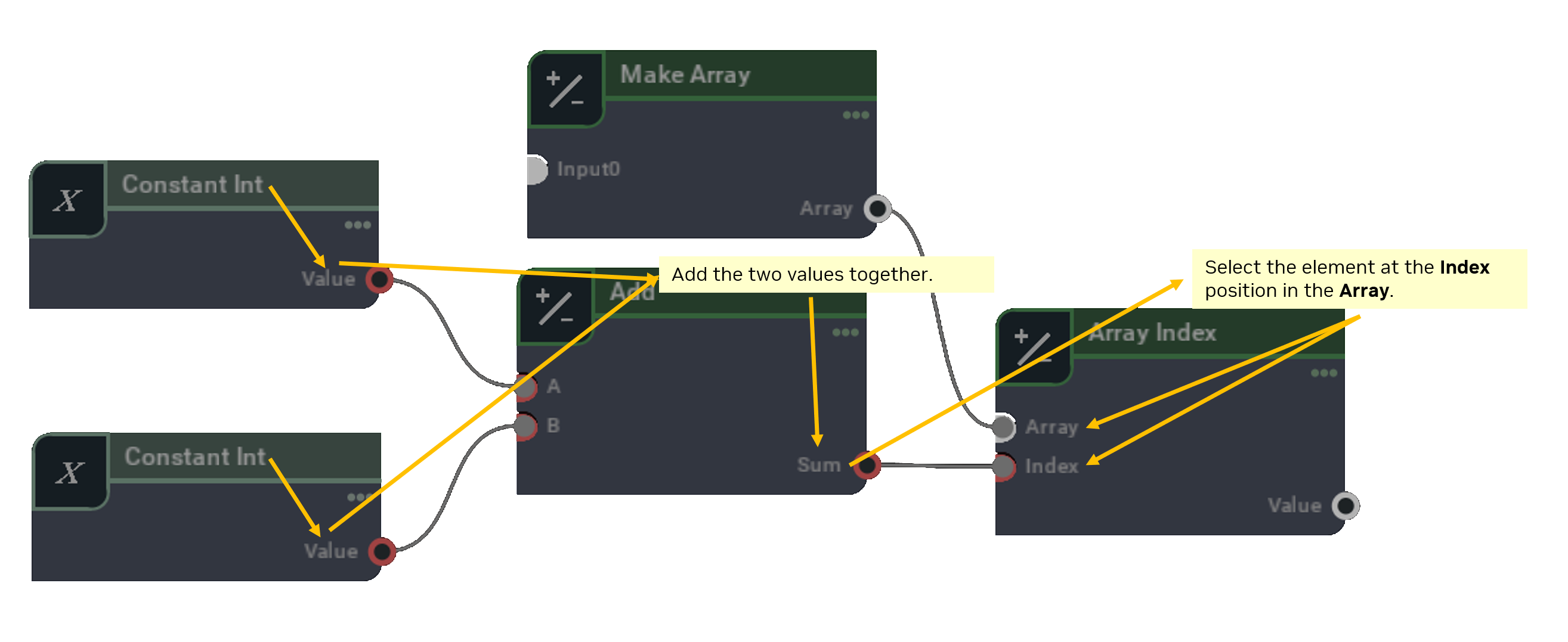
You can go a long way to figuring out if your names and descriptions are intuitive by looking at a graph in the graph editor and trying to read it as an english sentence.
As an example (where descriptions are bold and names are italicized) - take two Constant Integer values, Add the two values together to get the Sum of them. Using the Sum as an Index into an Array of values, Select the element at the Index position in the Array, and put the result in the Selected Value.
Here are some more specific tips that will help make the user’s experience with your node type more pleasant.
Avoid short forms in user-facing names and descriptions.
Avoid |
Prefer |
|---|---|
pts |
Points |
int |
Integer, 32-bit Integer |
xform |
Transform |
Explain or provide references for any terms that are not obvious from context.
Avoid |
Prefer |
|---|---|
This node type lets you access a Variant Set |
This node type lets you access a Variant Set. For more information on Variant Sets see https://openusd.org/docs/Authoring-Variants.html |
Be precise with names whenever possible.
Avoid |
Prefer |
|---|---|
Input Value |
Angle |
Output Value |
Cosine |
Include in the description the conditions in which a node type compute() can fail.
Avoid |
Prefer |
|---|---|
Sets the output to the result of the numerator divided by the denominator. |
Sets the output to the result of the numerator divided by the denominator. Fails if the denominator is approximately equal to zero. |
Be wary of ambiguous verbs. In a node type that multiplies two matrices describing the output as “The modified matrix” could either mean “A copy of the matrix with the modifications performed on it” or “The original matrix, modified by the multiplication”. The difference is important as the second implies that the original matrix is lost.
Avoid |
Prefer |
|---|---|
The modified matrix. |
The product of the two input matrices. |
Use roles when they are appropriate.
With This Description |
Avoid |
Prefer |
|---|---|---|
The points to deform. |
float[3][] |
pointf[3][] |
The color whose luminance is to be computed. |
double[3] |
colord[3] |
The name of the attribute need not repeat the type unless it is need for clarification.*
Avoid |
Prefer |
|---|---|
Prefix String |
Prefix |
Largest Integer |
Largest |
Blended |
Blended Color |
UI names are always capitalized, and multiple word names are separated by spaces.
Avoid |
Prefer |
|---|---|
transform |
Transform |
BlendedColor |
Blended Color |
xAxis |
X Axis |
When input attributes are equivalent, more generic names can be used. For example although the names are generic there is no confusion here between the inputs.
Name |
Attribute Description |
|---|---|
A |
The first of the two strings from which to find the longest. |
B |
The second of the two strings from which to find the longest. |
Longest |
The longest of the two input strings A and B. |
When referring to the attribute names in the node type description use the UI name since the UI is where the text will be read. In particular you can always omit the “inputs:” and “outputs:” namespaces when referring to attributes.
Avoid |
Prefer |
|---|---|
The longest of the two input strings “inputs:a” and “inputs:b”. |
The longest of the two input strings “A” and “B”. |
Nodes are “executed”, attributes are “computed”
Avoid |
Prefer |
|---|---|
When the node evaluates, calculate the output ‘RESULT’. |
When the node executes, compute the output ‘RESULT’. |