UV Layout Best Practices
A SimReady 3D asset has two recommendations when it comes to UV mapping:
Non-Overlapping UVs
Use UV Channel 1 only
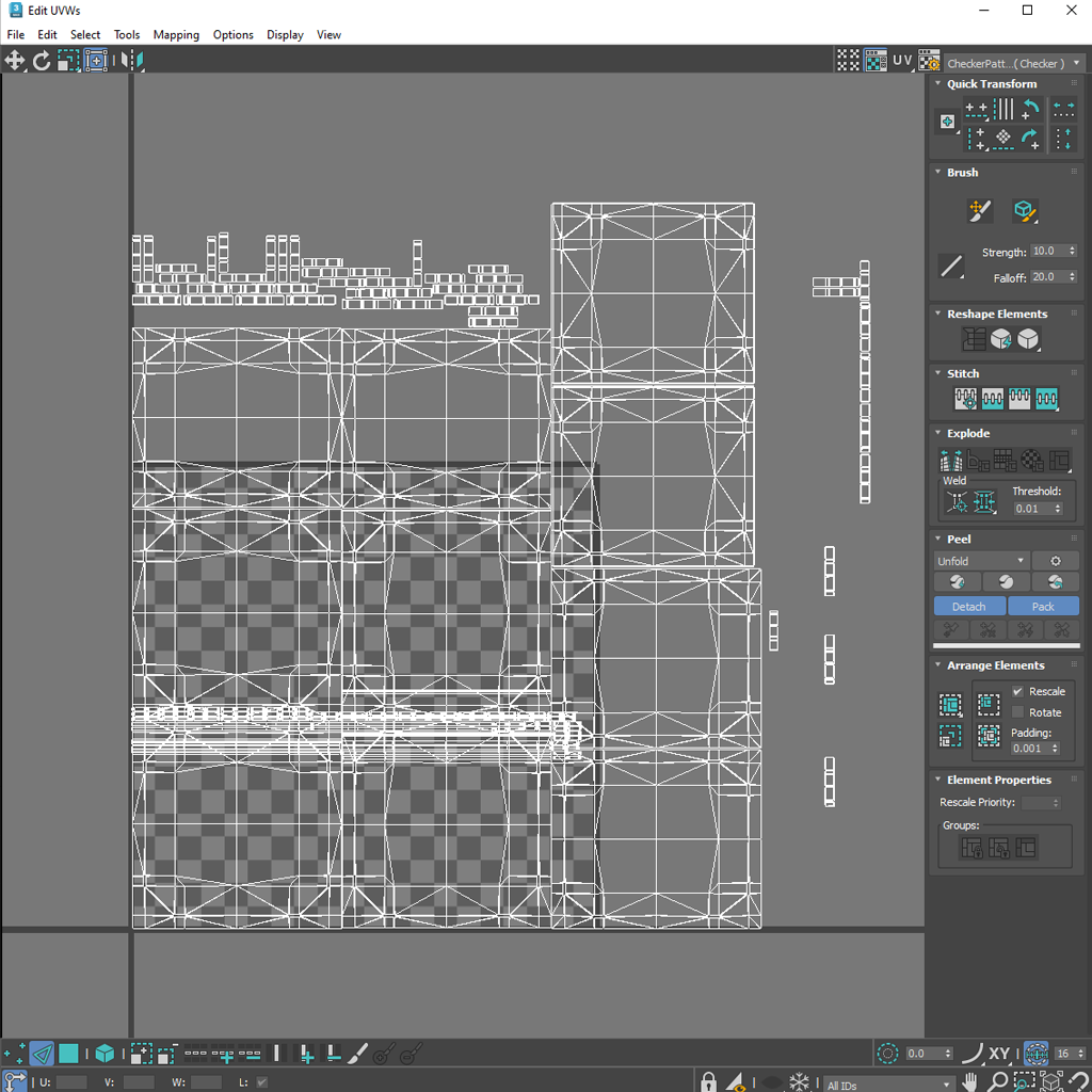
Every 3D asset that includes complex texture map layouts and is intended for simulation requires a specific UV mapping process. This results in a flattened 2D representation of the 3D object so texture maps can be accurately projected on its surface. Any modern DCC app is capable of processing these unwrapped UV Maps.
The resulting UV Map is normalized in UV space using values between 0 and 1. The UV space is defined by two axes, U and V, where U represents horizontal coordinates (X) and V coordinates (Y).
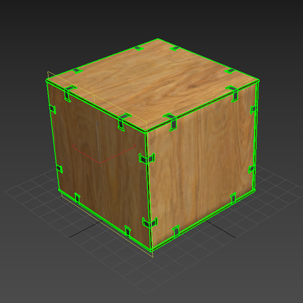
SimReady requires UV maps in order to render 3D assets correctly. Consequently, UV Mapping is an important part of the creation process intended for simulation.
Through UV mapping a 3D artist can assign multiple textures maps which significantly expedites the material creation process. There are several methods to separate a 3D model to generate successful UVs. A 3D artist can quickly experiment between manual and automatic unwrapping processes. This is why UV unwrapping workflows can vary significantly from artist to artist; there are several ways to get good results. Every approach provides different benefits a 3D artist can take advantage of. It is important to keep in mind which UV unwrapping approach will be used during the creation process. Planning ahead will most definitely help to avoid any unnecessary recreation of geometry at later stages of production.
Doing so will also ensure that your materials can be upgraded from older material types to newer as more advanced materials become available.
Defining Seams for UV Unwrapping
During the creation process, planning for where the unwrapping seams will be located is crucial. This will help to prevent the display of unwanted visible UV Map breaks causing bad materials rendering. Whenever possible, the goal is to place these breaks where natural transitions occur on the physical object that is being recreated. This is due to the fact that these seams will help to flatten the UV islands successfully so that texture maps can be applied with precision to the 3D model.
Some tileable patterns can cause seams to be more visible and difficult to hide. Placing seams behind other geometry could be a quick way to troubleshoot this issue. A 3D artist can also weld two UV islands together in order to avoid unwanted seams. In some situations, an artist can leave a small amount of UV distortion (stretching and compression) in order to keep some UV islands together for the sake of better materials rendering. It is important to practice good judgment when making these decisions. Here is an example of bad and good approaches to these type of situations:
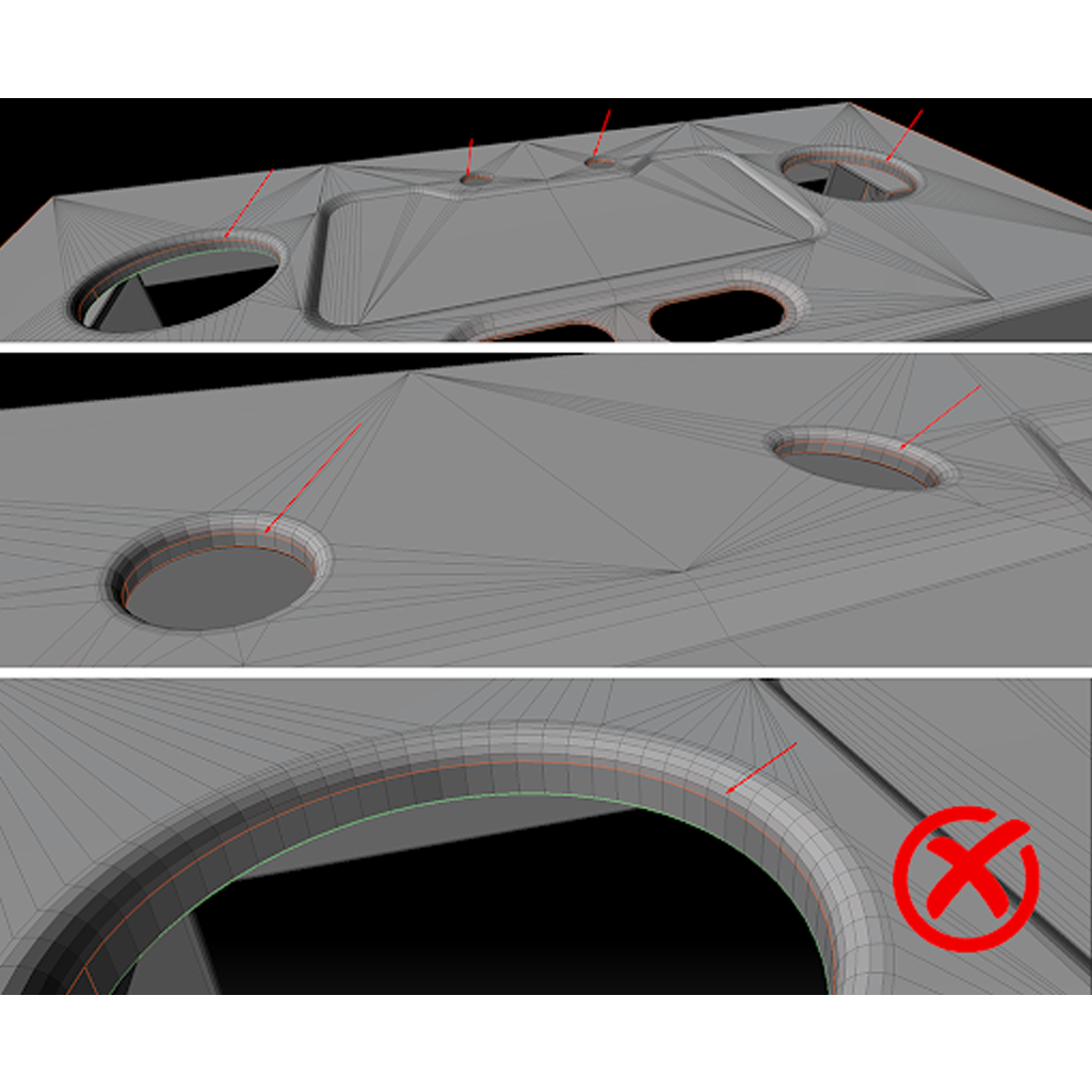
Don’t place seams in the middle of holes geometry
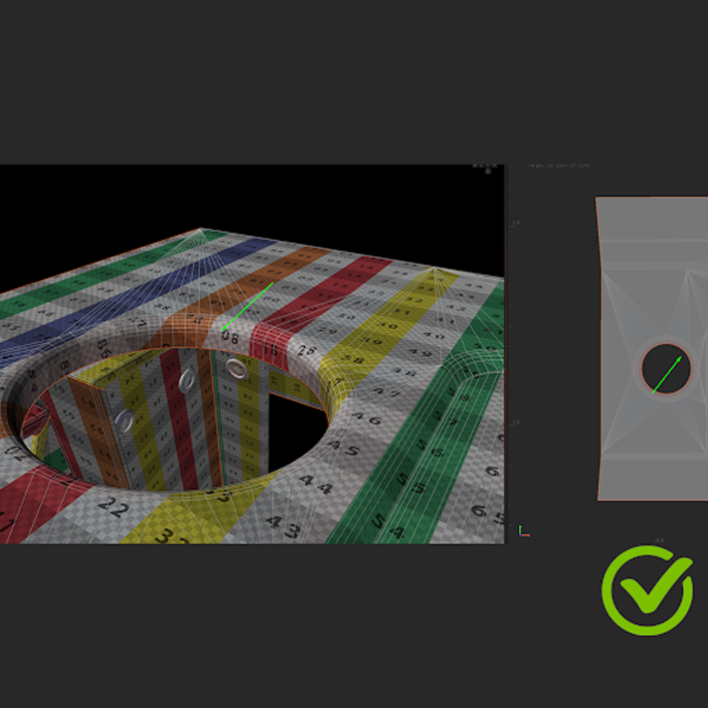
Extending seams to base of holes adds a tiny bit of distortion but is better for mapping
Keep the following recommendations in mind when planning UV unwrapping for SimReady 3D assets:
UV breaks or seams should follow the natural structure of the object
For more complex 3D models, make sure to place the UV seams away from important viewing angles
Limit the number of UV islands or shells to help make material creation work easier
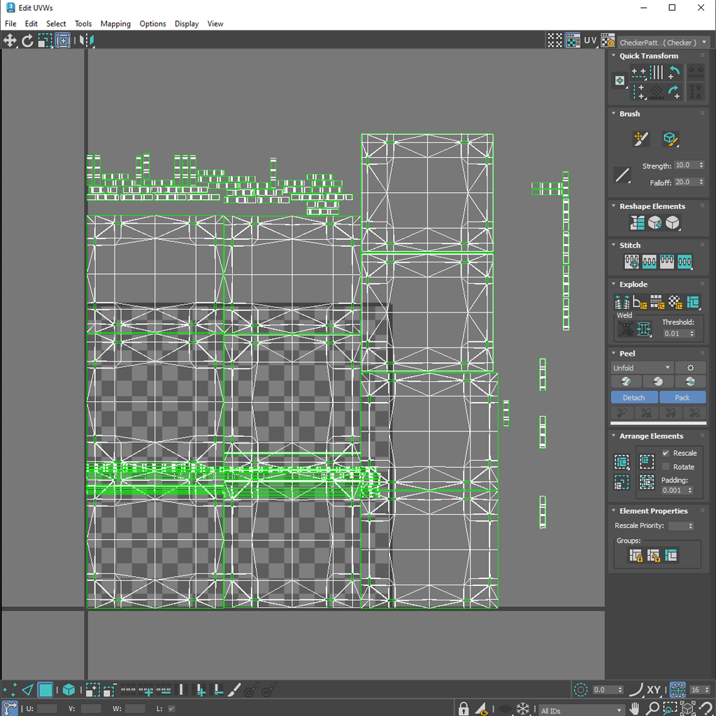
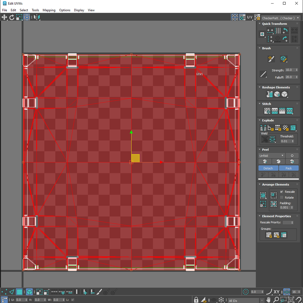
Make sure that there are no overlapping UV shells in the 3D model
Limit your UV unwrapping workflow to using UV Channel 1 only
Make sure that UV islands are oriented correctly to help with the natural flow of patterns on texture maps that are intended for the object in question
There will be times when separating the 3D model into parts or GeomSubsets will be necessary. The key in these cases is to be very strategic regarding the placement of UV seams and to hide them whenever possible.
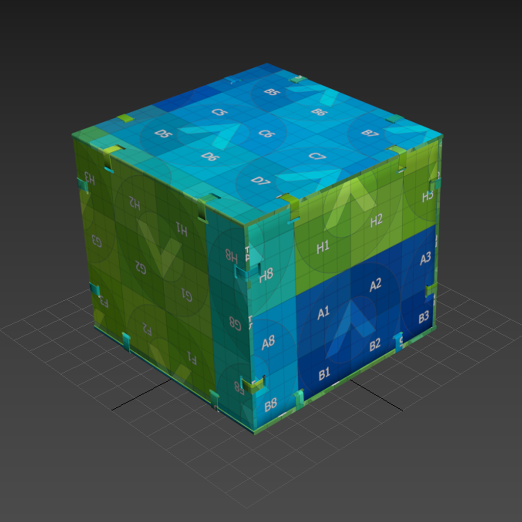
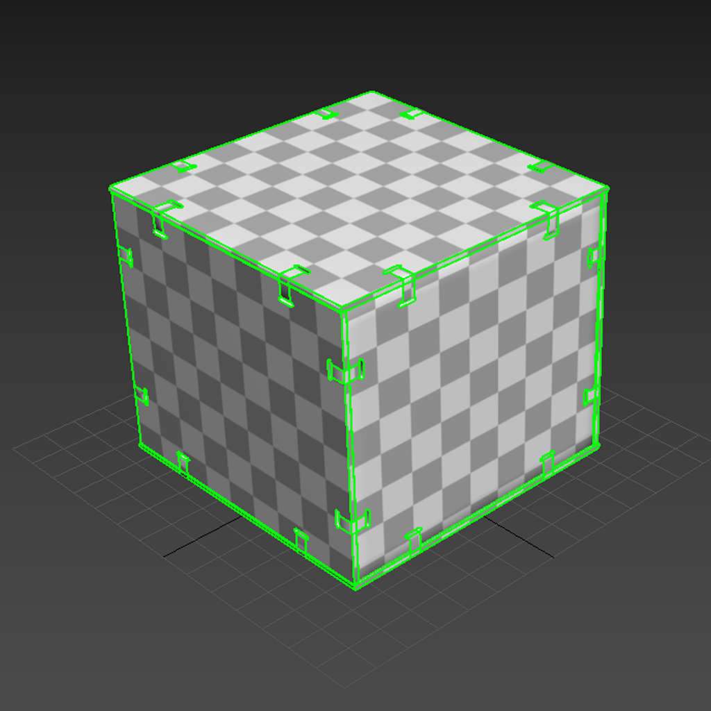
UV Coherence
Working with UVs will require the use of visual aid texture maps, or UV Grid Bitmaps, that can help to quickly identify where poor orientation and distortion occurs when unwrapping a 3D model. Modern DDC apps provide users with a couple of UV Grid bitmaps that can be used for this purpose. 3D artists should also be able to import their own custom texture maps if needed. Usually these texture maps include easily identifiable grid lines, shapes and text that can be used to visualize artifacts or errors on 3D surfaces. 3D artists can also use these UV grid textures maps to understand the overall size or scale of the 3D model. Keep in mind the following recommendations when reviewing UV map coherence:
Look for poorly oriented UV shells
Flipped UVs facing the wrong direction
Keep UV Grid textures evenly squared to minimize distortion, stretching, or tearing
Ensure relative scale between UV islands (texel density)
Modern DDC apps include visible aid tools or features that make it easier to identify errors during the unwrapping process. Generally, this is done by displaying problem areas using color coding which makes this process a lot more intuitive. DDC apps also include tools or features that facilitate UV packing that helps to keep texel density homogeneous and organized. Some of these tools also include automatic re-orienting features. However, most of the time 3D artists like to have control over how UV islands are oriented.
Generally, it is best to target a minimum texel density of 512 pixels/meter for simulation. Currently, we recommend that the maximum texture resolution be kept at 4096x4096, and non-square textures are allowed. In order to achieve this resolution, UDIMs can be used. However, what is most important is a consistent texel density. If you need help understanding texel density and UDIMs, please refer to these articles:
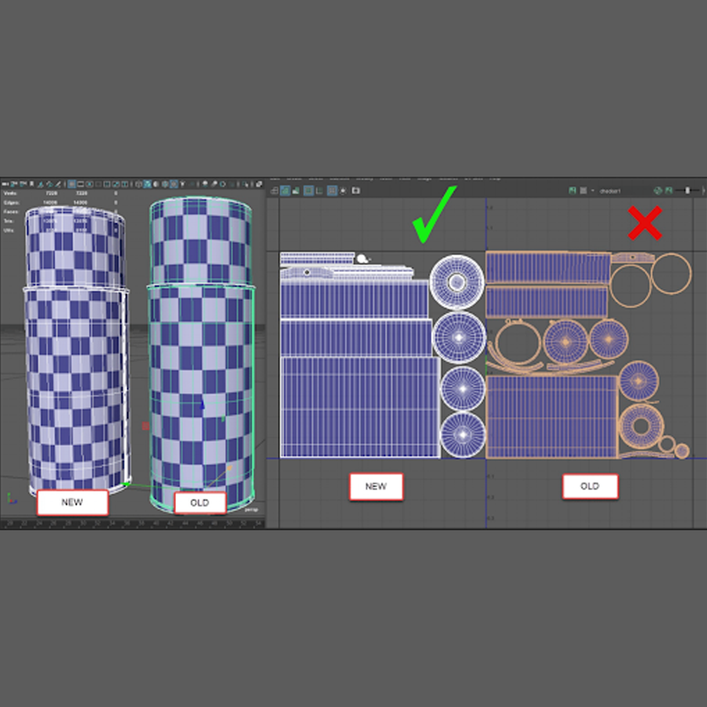
Here are a couple of additional tips that can be used to help ensure the UV Unwrapping workflow is consistent:
Keep all cylindrical UV islands straight so these can be packed in either a horizontal or vertical orientation. This will avoid the introduction of diagonal lines in texture bakes which result in lower resolution and artifacts.
Avoid creating thin strip UV islands. Instead, straighten them and then attach them to vertical or horizontal UV islands.
Keep UV islands oriented consistently to help make it easier to stamp fonts, alphas, and logos, as well as applying patterns like directional grains (e.g. brushed metals, wood, or directional scratching) on the 3D models.
Make sure that UVs are relaxed to maintain proper texel density between all UV shells.
UVs and Real World Scale
It is very important to stay true to real world dimensions when 3D modeling an asset for SimReady. This will impact how the 3D model behaves regarding lighting, animation and physics for example. This level of compliance will also make texturing work easier to troubleshoot. The goal is to create UV islands capable of rendering the correct, real world size of the physical material sample. Most 3D artists target the use of the 1 UV = 1 Meter standard. By following a UV to world scale standard, materials that have been created with real-world size in mind will maintain proper scale as default behavior when applied.
To summarize, 3D assets intended for SimReady require a coherent UV workflow. This will guarantee full fidelity visualization throughout the array of render engines within a simulation platform. We encourage 3D artists to plan ahead before starting work on UV layout to ensure that there is less troubleshooting in later stages of production. Affording this piece of mind early on will assure a more predictable and enjoyable time during the material and texture creation processes.