Patch Manager Extension
Overview
The Patch Manager data center extension in NVIDIA Omniverse enables users to import and visualize layout and connectivity data from the Patch Manager Infrastructure Management application. It allows users to explore and analyze their data center infrastructure, including racks, servers, switches, and cables, with accurate representations of the physical layout and connectivity.
With this extension, users can simulate changes to the data center infrastructure, assess the impact of modifications, and explore different layouts before implementing them in the physical environment. This helps reduce downtime and improve operational efficiency.
In summary, the data center extension in NVIDIA Omniverse offers a powerful tool for visualizing, analyzing, and optimizing data center infrastructure, empowering users to make informed decisions.
Pre-Requisites
The latest installation of Patch Manager Infrastructure Management v6.4.x with REST API access.
Hardware Templates imported into Patch Manager Infrastructure Management application.
Note
Contact support@patchmanager.com to obtain hardware templates. These are required to run with the Patch Manager Extension.
Enabling Patch Manager Extension
The Patch Manager Extension is not enabled by default in Omniverse USD Composer and will need to be enabled for use.
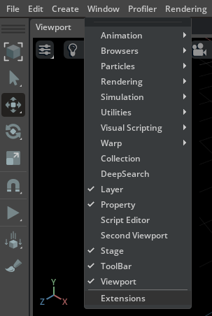
Open Omniverse USD Composer and click on Window -> Extensions to open the Extensions Manager.
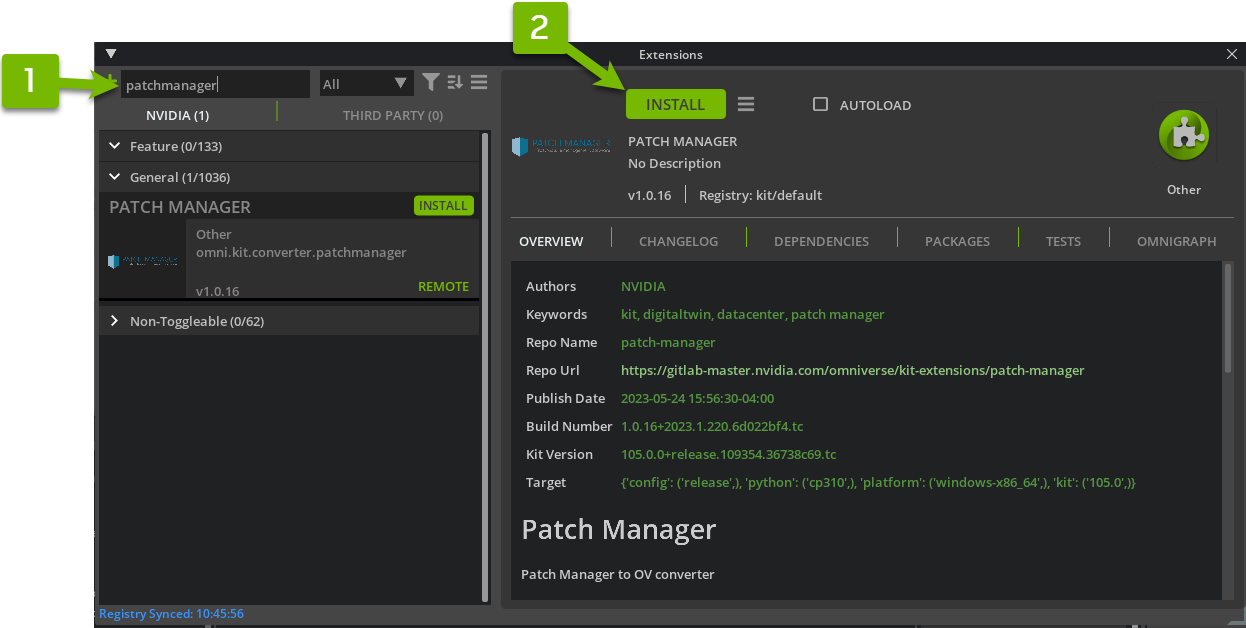
Install and enable the Patch Manager Extension.
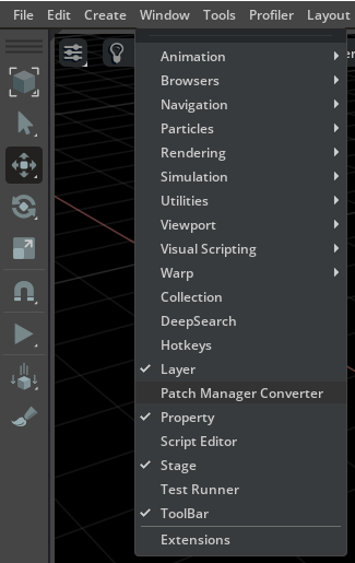
Click on Window -> Patch Manager Converter to open the Extension Window
Quick Start Guide
Server Login
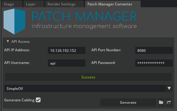
Enter REST API configuration and user credentials
Click Login
Data Center Generation
Upon a “Successful” login attempt, select a data center from the drop-down menu and click Generate.
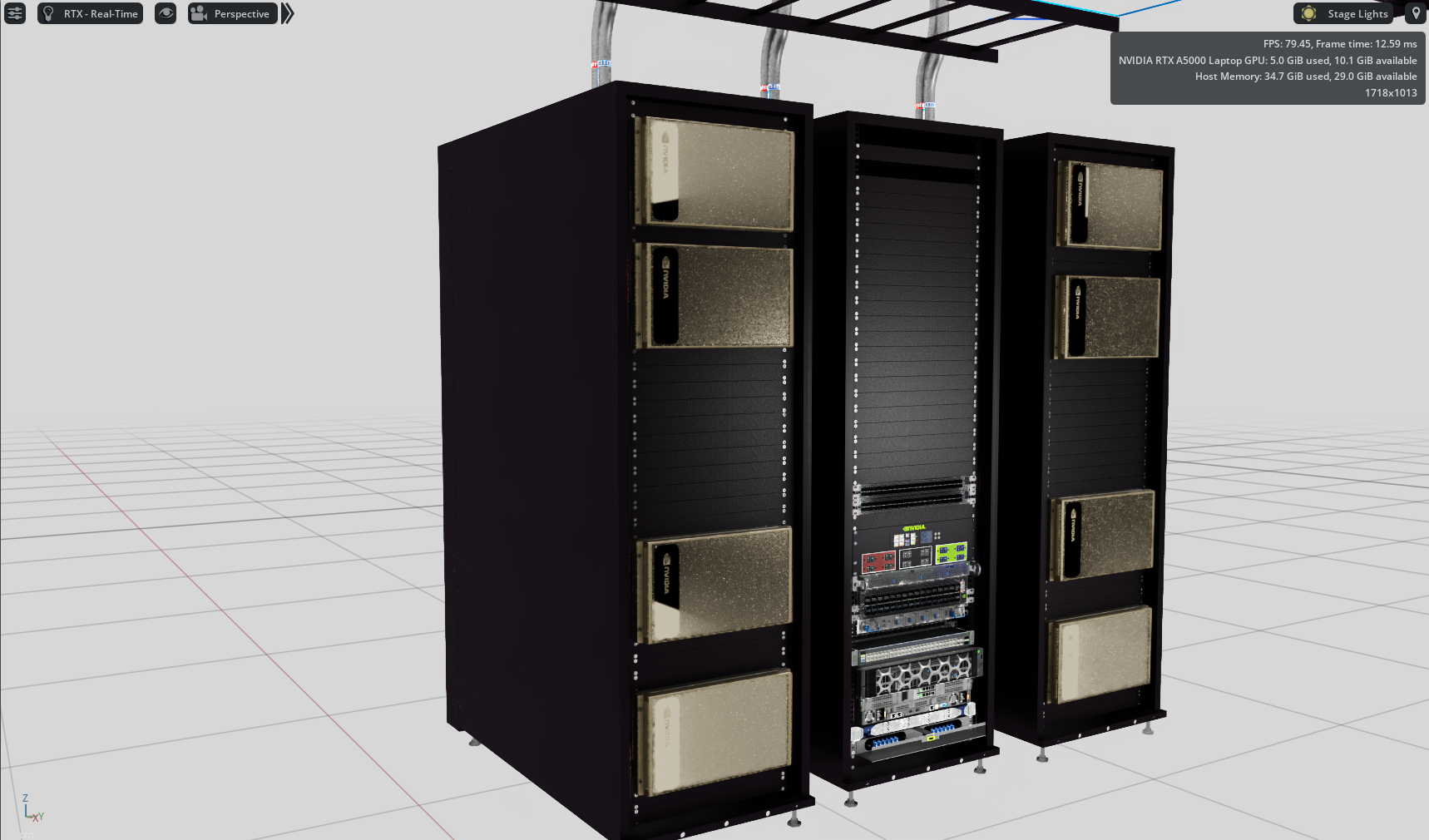
After clicking “Generate,” the extension will display your selected data center layout
Note
Upon the initial use of the extension, you may encounter a prompt to upload XML files to your Patch Manager server. Follow the instructions in API Data Format Upload.
Note
Generating data center digital twins can take up to a few minutes as the initial download size of the models may be large. Subsequent attempts with the same models will load faster.
API Data Format Upload
Uploading data formats to the Patch Manager database is crucial for the functionality of the Patch Manager extension. It facilitates the retrieval of essential data needed to create the data center layout within Omniverse. If prompted to upload, please follow the steps below.
Once prompted, the user will be asked to upload XML files to the data base if the configuration hasn’t taken place.
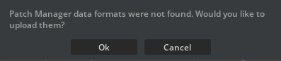
Select OK to begin the XML file uploading process.
The upload process will begin, and the user shall now be able to click Generate to create the data center.
Technical Documentation
User Interface
A docked window next to the Stage tab is shown after toggling on the Patch Manager Converter option.
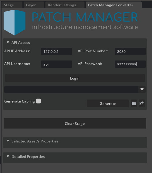
Descriptions of each configuration element are below:
Element |
Description |
|---|---|
API IP Address |
|
API Port Number |
|
API Username |
API credentials |
API Password |
API credentials |
Descriptions of the Generation elements are below:
Element |
Description |
|---|---|
Login |
|
Drop-down/ComboBox |
Menu will populate with a list of available data centers |
Generate Cabling |
If enabled, will generate available cabling data |
Generate |
Generates the user-selected data center |
Visualizing Data Center details
Selected Asset Properties
This UI element located within the extension window will provide insight into a selected asset’s properties. These properties can be unique to the type of asset selected. For example, here are a list of properties displayed when a cable is selected.
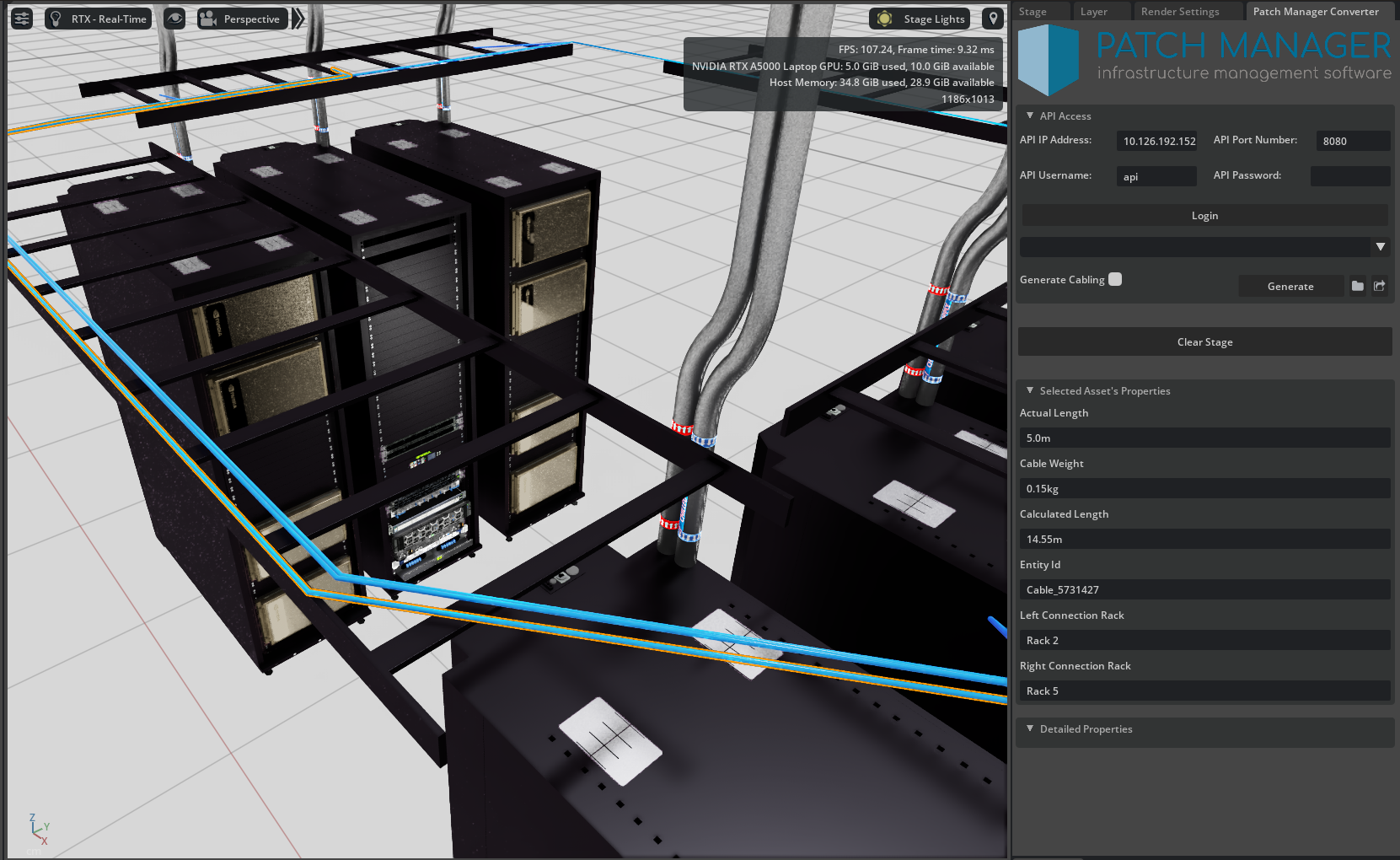
Similarly here are the properties displayed when network equipment is selected.
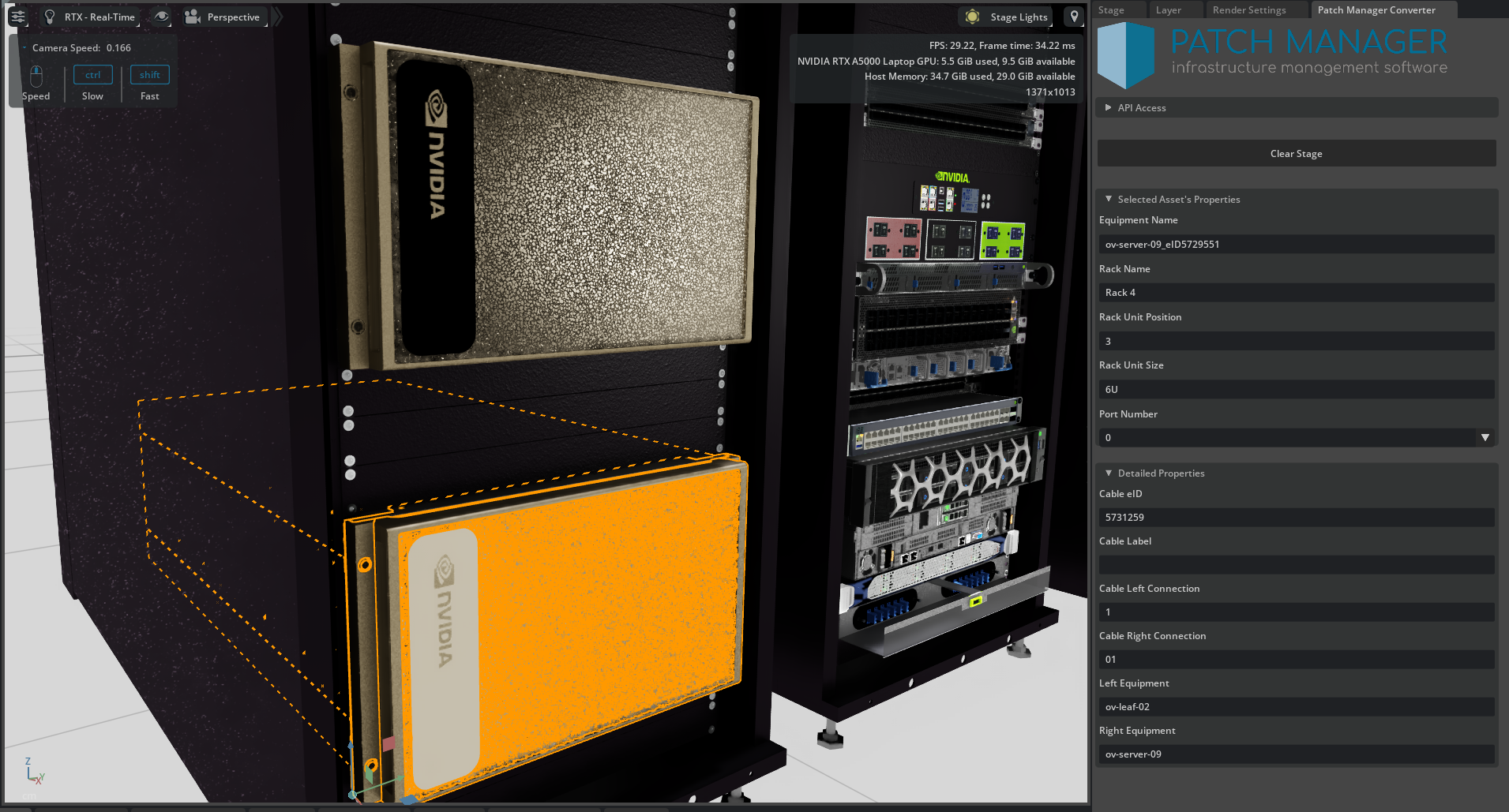
Detailed Properties
This UI element will provide additional insight into a selected asset’s properties. These additional properties are available based on the type of asset selected (e.g., cable vs rack).
Asset Mapping
The Patch Manager extension includes a .csv file used to create asset mapping between Patch Manager application and the extension. This spreadsheet plays a vital role in the extension’s operation by facilitating the mapping between Patch Manager Hardware Templates and the Omniverse Data Center Sim Ready Asset Library. Without this spreadsheet, the mapping process cannot take place, and the generation of the data center’s 3D digital twin becomes infeasible.
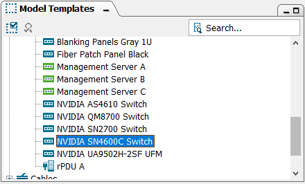
This spreadsheet can be accessed by clicking the Folder icon in the extension UI. Once opened, you will find information regarding each asset’s name, position, rotation, mapped USD path, etc. It is important for the names any hardware templates used in Patch Manager to be copied precisely into the asset name column of the csv.
For example, here is a Hardware Template in Patch Manager’s Model Templates window and its corresponding entry in the assetMapping.csv file.

Note
For a valid mapping to occur, the Equipment Template entries in the .csv must match the Hardware Template name in Patch Manager. If the extension finds a match, it will reference the USD Path column in the spreadsheet to swap in the 3D asset.
If hardware from Patch Manager application is not matched to an Omniverse Sim Ready asset, the extension will add a broken reference to the prim C:/unmatchedReference_<asset_name>. This allows for a simple post-generation asset swapping.
CSV Asset Mapping file
As described above, the asset mapping file is essential to the proper generation of the digital twin data center. In this section we’ll go over each column and how it affects your data center assets.
Equipment Template: Unique asset name. This must be identical to the Patch Manager Hardware Template being used (e.g., “NVIDIA SN4600C Switch”) as it is used to match equipment to their respective USD model.
XYZ (Front/RearMount/Rear): These columns provide the flexibility to apply offsets to assets, such as equipment, allowing for precise adjustments to ensure optimal fitment within a rack. These values can be modified according to the specific rack mount position requirements.
For racks, these XYZ values are offsets from the origin of the rack to the first RU slot.
For equipment, these offsets are added on top of the rack offsets. These are typically 0/0/Z. You may adjust the fitment of equipment along the X-Y dimensions; however, Z is not adjustable as it is dependent on the rack unit (RU) position.
These offsets can change depending on how the equipment is mounted (i.e., Front/Rear/Rear Mount).
Rotation (Front/RearMount/Rear): Rotation may be adjusted for each individual asset. Offsets are applied based on the equipment’s mounting orientation/position.
For racks, these XYZ values are offsets from the origin of the rack to the first RU slot.
For equipment, these offsets are added on top of the rack offsets. These are typically 0/0/Z. You may adjust the fitment of equipment along the X-Y dimensions; however, Z is not adjustable as it is dependent on the rack unit (RU) position.
These offsets can change depending on how the equipment is mounted (i.e., Front/Rear/Rear Mount).
USD Path: A valid file path to USD file. This can be a
nucleus url (omniverse://<asset_path>.usd)
local file system path (C:/<asset_path>.usd)
web url (http://omniverse-content.com/Assets/DataCenter/<asset>.usd)
Length(cm): This column is reserved for cable tray segments lengths
Used for cable tray segment included in asset path.
May be used for custom cable tray segments.
Asset Swapping
There are two methods to replace unmatched assets using the Patch Manager extension.
Method 1: USD Paths Extension
Selecting the “find” icon will enable the USD Paths Extension and trigger a search across the stage for prims that have attached “References”. This feature proves to be useful for efficiently identifying and replacing broken paths throughout the entire stage, saving time and effort.
Shown below is an example of USD Paths listing all USD references (incl. unmatched reference paths).
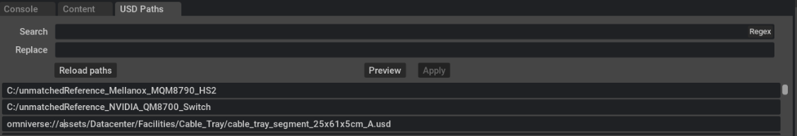
To replace an unmatched reference, the user can perform a copy/paste operation into the “Search” text field, entering the new asset’s path in the “Replace” text field. Clicking “Preview” will display the changes below, and clicking “Apply” will apply the updates to the stage.
Note
Utilizing Method 1 will result in changes being applied across the entire stage.
Method 2: Prim Select Asset Swap
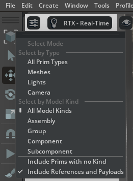
An alternative choice is to directly select the rack that has a missing USD reference, resulting in a red bounding box being displayed. By selecting this box, the user will be prompted to replace it with a model chosen through the file picker. This will allow the user to replace the single instance or all similar instances within the scope of the rack. The user can then navigate through the file picker to choose the .USD model to swap in.
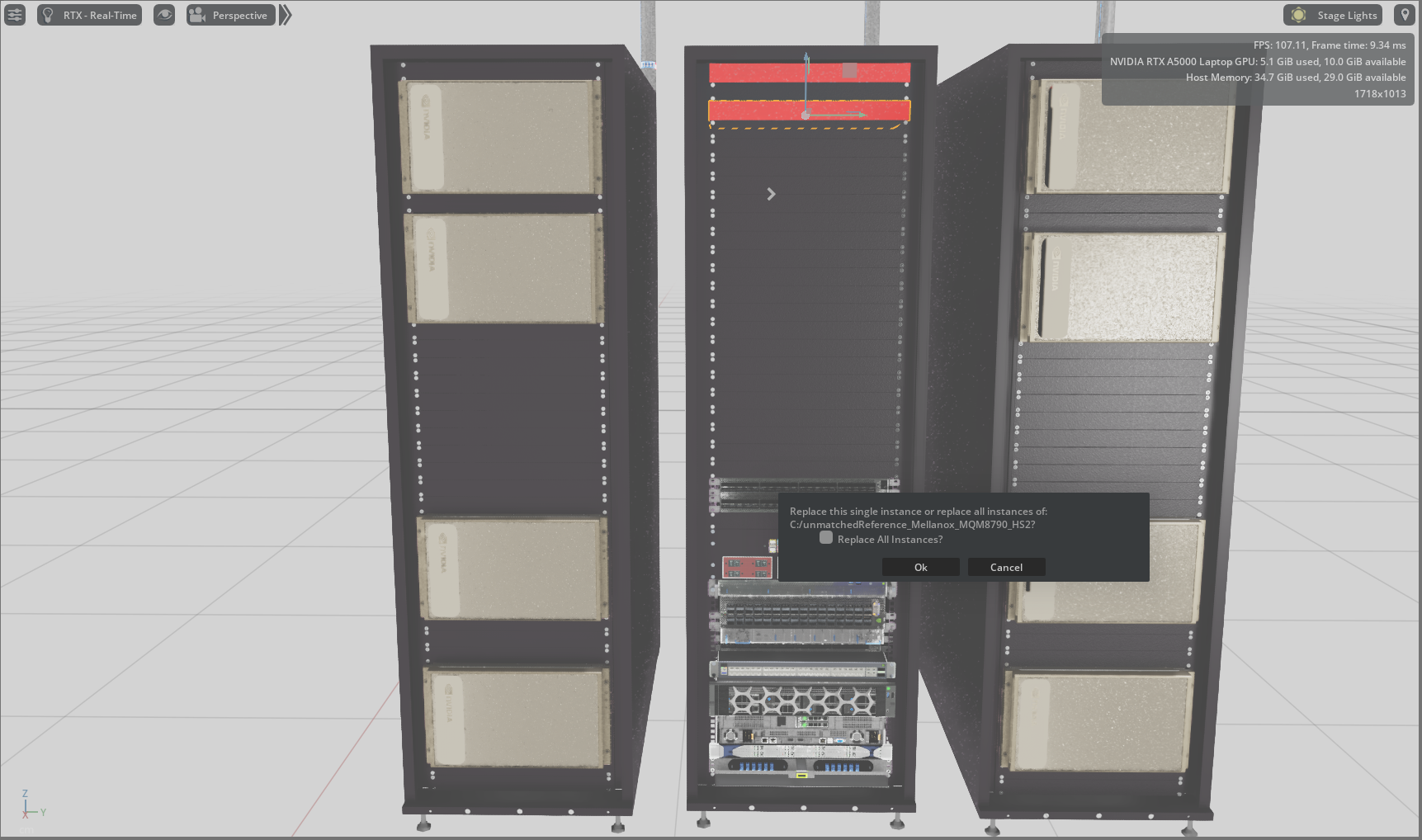
This feature works best using USD Composer’s default selection mode, “Model” and “Include Prims with no Kind” set to “unchecked”.
Note
Utilizing Method 2 will result in changes being applied within the selected rack.
Helpful Modeling Guidelines
Asset Mapping Guidelines
Ensure Hardware Templates in Patch Manager are Unique - When adding custom hardware templates in Patch Manager, it is important to avoid naming them similarly to prevent incorrect matching. For instance, if there are two templates with the following names, there is a possibility of “NVIDIA DGX A100” being matched to either of the entries below.
NVIDIA DGX A100
NVIDIA DGX A100 Power Module
This may be avoided by naming the first entry as “NVIDIA DGX A100 Server”.
Cable / Cable Tray Guidelines
The generation of right angle cable trays is currently supported, while support for angular cable trays is not yet available.
Best practices for cable generation are
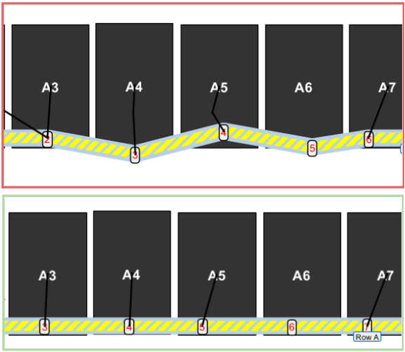
Cable trays should not be overlapping one another (width of tray must also be accounted for)
Cable trays should be aligned
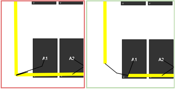
Entry and exit points should be created in front of each rack containing cables
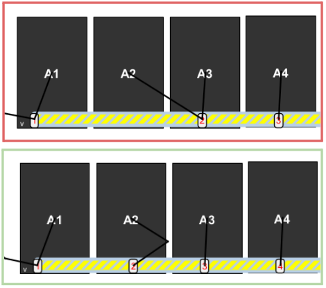
Entry and exit points should be created in-between intersecting cable trays
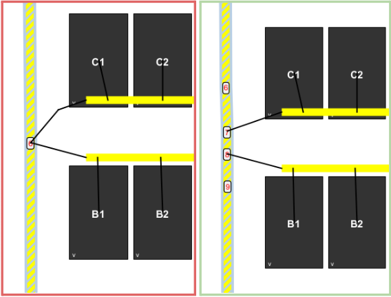
Cable tray height (z-values) are non-zero
Cable z-values are also non-zero
Release Notes
USD Composer 2023.1 Initial Release with Sim Ready Asset Library
Attributions
Future Work
High fidelity cabling
Equipment submodule support