Omniverse Camera Extension#
Introduction#
In Omniverse the camera sensor and ISP simulation is simulated in both the renderer (via shaders) and in post processing tasks implemented in CUDA controlled by a USD schema. The camera sensor and ISP simulation is controlled by setting parameters in the USD stage.
A separate depth camera sensor simulation is available as a post process operation in the renderer.
An deprecated Omnigraph node camera sensor and ISP simulation also exists. The Omnigraph node camera simulation is developed by connecting camera task nodes and defining a camera pipeline/graph. The developer could start with a simple runnable camera graph and could improve the simulation fidelity by adding new tasks and tweaking the graph node settings. For the most part the lens simulation is done directly in the renderer.
The camera sensor and ISP simulation is described first and the depth sensor is described in a later section.
Render Options#
RTX Raytracing Renderer : Realtime renderer based on raytracing with optimizations to run in real time
RTX Pathtracing Renderer: Perception Renderer which focus more on light precision than on real time
IRAY Photoreal Renderer: Renderer for experimental spectral rendering (only offline rendering)
Render Image Data#
The rendering is currently provided in three precisions:
RGBA Low Dynamic Range (LDR)#
8-bit sRGB with alpha channel. This precision is only used for the depth camera sensor simulation.
Primaries |
4 : Red, Green, Blue, Alpha |
Minimum Component Value |
0 |
Maximum Component Value |
255 |
RGBA High Dynamic Range (HDR)#
16-bit floating point HDR RGB with alpha channel, linear mapable to physical luminance units like cd/m^2. This precision can be used for the visual camera sensor and ISP simulation.
Primaries |
4 : Red, Green, Blue, Alpha |
Minimum Component Value |
0.0 |
Maximum Component Value |
65504.0 |
RGBA High Dynamic Range (HDR)#
32-bit floating point HDR RGB with alpha channel, linear mapable to physical luminance units like cd/m^2. This precision can be used for the visual camera sensor and ISP simulation.
Primaries |
4 : Red, Green, Blue, Alpha |
Minimum Component Value |
0.0 |
Maximum Component Value |
Max IEEE-754 float32 value |
Camera Sensor and ISP simulation#
The camera sensor and ISP simulation begins with a rendered image and applies a series of operations to simulate the camera sensor and ISP. These operations are described below. The simulation always begins with a 16bit or 32bit HDR image.
Here is the full simulation pipeline:

The camera sensor and ISP simulation is enabled by adding the “OmniSensorGenericCameraCoreAPI” schema name to a camera prim and supplying the relevant parameters. The “modelName”, “modelVendor”, and “marketName” parameters must be set as follows to enable the simulation:
string omni:sensor:modelName = "CameraCore"
string omni:sensor:modelVendor = "NVIDIA"
string omni:sensor:marketName = "Generic"
The “modelName” parameter must be set to “CameraCore” to enable the simulation. The “modelVendor” parameter must be set to “NVIDIA” to enable the simulation. The “marketName” parameter must be set to “Generic” to enable the simulation.
To obtain simulation output, the AOV “HdrColor” must be requested. One or both of the AOVs “OmniCameraSensorPreIsp” or “OmniCameraSensorPostIsp” must be requested.
HdrColor configures the renderer to create a 16bit or 32bit HDR image. This is used as input to the camera sensor and ISP simulation.
OmniCameraSensorPreIsp requests a simulation of a camera sensor up to just before ISP processing. This is typically the ‘RAW’ image.
OmniCameraSensorPostIsp requests a simulation of a camera sensor and ISP processing. This produces an RGB image that is used for display.
Example Camera Prim
This is an example of how to define a Camera sensor in USD:
def Camera "camPersp2" (
  prepend apiSchemas = ["OmniSensorGenericCameraCoreAPI"]
)
{
  string omni:sensor:modelName = "CameraCore"
  string omni:sensor:modelVersion = "0.0.0"
  string omni:sensor:modelVendor = "NVIDIA"
  string omni:sensor:marketName = "Generic"

  bool omni:sensor:core:colorCorrectionRedBlueSwap = false
  float omni:sensor:core:colorCorrectionFullwellBlack = 1.0
  bool omni:sensor:core:colorCorrectionOutputFloat16 = true
  bool omni:sensor:core:colorCorrectionApplySaturation = false
  float omni:sensor:core:colorCorrectionBlack = 0.0
  float omni:sensor:core:colorCorrectionMatrixRr = 1.0
  float omni:sensor:core:colorCorrectionMatrixRg = 0.0
  float omni:sensor:core:colorCorrectionMatrixRb = 0.0
  float omni:sensor:core:colorCorrectionMatrixGr = 0.0
  float omni:sensor:core:colorCorrectionMatrixGg = 1.0
  float omni:sensor:core:colorCorrectionMatrixGb = 0.0
  float omni:sensor:core:colorCorrectionMatrixBr = 0.0
  float omni:sensor:core:colorCorrectionMatrixBg = 0.0
  float omni:sensor:core:colorCorrectionMatrixBb = 1.0
  float[] omni:sensor:core:colorCorrectionWhiteBalance = [0.9, 0.8, 1.2]
  float[] omni:sensor:core:colorFilterArrayCfaCf00 = [0, 1, 0]
  float[] omni:sensor:core:colorFilterArrayCfaCf01 = [1, 0, 0]
  float[] omni:sensor:core:colorFilterArrayCfaCf10 = [0, 0, 1]
  float[] omni:sensor:core:colorFilterArrayCfaCf11 = [0, 1, 0]
  token omni:sensor:core:colorFilterArrayCfaSemantic = "GRBG"
  token omni:sensor:core:colorFilterArrayOutputDataTypeFormat = "UINT32"
  int omni:sensor:core:colorFilterArrayMaximalValue = 16777215
  bool omni:sensor:core:colorFilterArrayFlipHorizontal = false
  bool omni:sensor:core:colorFilterArrayFlipVertical = false
  float omni:sensor:core:noiseDarkShotNoiseGain = 10.0
  float omni:sensor:core:noiseDarkShotNoiseSigma = 0.5
  float[] omni:sensor:core:noiseHdrCombinationData = [[5.8, 4000], [58, 8000], [70, 16000]]
  int omni:sensor:core:compandingAlignment = 15
  int omni:sensor:core:compandingPostPedestal = 0
  int omni:sensor:core:compandingPrePedestal = 0
  float[] omni:sensor:core:compandingLinearCompandCoeff = [
    [0, 0],
    [512, 512],
    [65536, 1024],
    [16777215, 4095]
  ]

  string omni:sensor:core:ispSmodelCameraProgram = "AAAAAA.....   "

  string omni:sensor:core:introspectionOutputFileDirectory = "/output_dir/"
  bool omni:sensor:core:introspectionOutputFileEachFrameOneFile = true
  bool omni:sensor:core:introspectionOutputFileOnlyLastFrame = true

  string omni:sensor:core:introspectionInputRawPath = "/input_dir/image.raw"
  int omni:sensor:core:introspectionInputRawWidth = 1280
  int omni:sensor:core:introspectionInputRawHeight = 720
  int omni:sensor:core:introspectionInputRawSkipFront = 1280
  int omni:sensor:core:introspectionInputRawSkipBack = 2560
  string omni:sensor:core:introspectionInputRawFileDataType = "UINT16"
  bool omni:sensor:core:introspectionInputRawLoop = true

  # other camera parameters
}
Example RenderProduct
This is an example of how to define a Camera sensor render product in USD:
def Scope "Render"
{
  def Scope "Vars"
  {
    def RenderVar "hdrColor"
    {
        uniform string sourceName = "HdrColor"
    }

    def RenderVar "OmniCameraSensorPreIsp"
    {
        uniform string sourceName = "OmniCameraSensorPreIsp"
    }

    def RenderVar "OmniCameraSensorPostIsp"
    {
        uniform string sourceName = "OmniCameraSensorPostIsp"
    }
  }

  def RenderProduct "OmniSensorGenericCameraCoreRenderProd"
  {
    rel camera = </camPersp2>
    rel orderedVars = [
        </Render/Vars/hdrColor>,
        </Render/Vars/OmniCameraSensorPreIsp>,
        </Render/Vars/OmniCameraSensorPostIsp>
    ]
    uniform int2 resolution = (1280, 720)
  }
}
Camera Operations and their parameter settings#
Color Correction#
Introduction
To adapt to the color space and the dynamics of a real camera sensor this task applies a color correction, dynamic range limiting and constant white balance. With these parameters the user can consider items like exposure and color shift of image sensors.
Parameters & Attributes
Parameter Name |
Description |
Value Type |
Value Range |
Default Value |
Example |
|---|---|---|---|---|---|
colorCorrectionFullwell |
The value range of the output from the black level value to saturation |
float |
full range |
1.0 |
|
colorCorrectionBlack |
Black level |
float |
full range |
0.0 |
|
colorCorrectionOutputFloat16 |
Indicates whether the output shall be float16 or uint8_t |
boolean |
0,1 |
1 |
|
colorCorrectionOutputFloat32 |
Indicates whether the output shall be float32 or uint8_t |
boolean |
0,1 |
0 |
|
colorCorrectionMatrixRr |
Red to Red conversion |
float |
full range |
1.0 |
|
colorCorrectionMatrixRg |
Red to Green conversion |
float |
full range |
0.0 |
|
colorCorrectionMatrixRb |
Red to Blue |
float |
full range |
0.0 |
|
colorCorrectionMatrixGr |
Green to Red |
float |
full range |
0.0 |
|
colorCorrectionMatrixGg |
Green to Green |
float |
full range |
1.0 |
|
colorCorrectionMatrixGb |
Green to Blue |
float |
full range |
0.0 |
|
colorCorrectionMatrixBr |
Blue to Red conversion |
float |
full range |
0.0 |
|
colorCorrectionMatrixBg |
Blue to Green conversion |
float |
full range |
0.0 |
|
colorCorrectionMatrixBb |
Blue to Blue conversion |
float |
full range |
1.0 |
|
colorCorrectionRedBlueSwap |
swaps the red and blue component (RGBA->BGRA or BGRA->RGBA) |
boolean |
0,1 |
0 |
|
colorCorrectionWhiteBalance |
Defines the general gain for each color component after the CCM, could also be used to scale the values to the image sensor’s digital number (DN) |
float3 |
full range |
[1.0, 1.0, 1.0] |
[0.8, 1.9, 1.3] |
colorCorrectionApplySaturation |
Indicates whether the saturation parameters should be applied |
boolean |
0,1 |
0 |
Color Filter Array#
Introduction
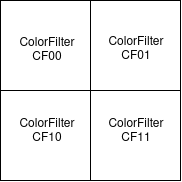
Camera sensors are equipped with a color filter array (CFA) to capture the color information, where the most used pattern is the 2x2. This tasks converts the RGBA images into 2x2 CFA images, which is the common image raw format in cameras. In theory you could use any 2x2 CFA pattern, the color filters could be defined individually.
RCCB (Red-Clear-Clear-Blue) is a frequently used CMOS camera color scheme in ADAS/AD, with obvious advantage that clear pixels provide more low-light sensitivity, thus leading to lower noise in low light scenarios than other schemes. A disadvantage is the lower color separation, which could lead to problems in color sensitive applications e.g. with traffic lights (red vs orange).
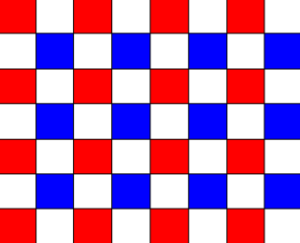
This task could be also used to encode RGGB Outputs or other CMOS 2x2 mosaic encodings(like RCCC) by setting the CFA weights accordingly. RGGB has the advantage of a better separation of the colors and the easier conversion to common color spaces as RGB/YUV.
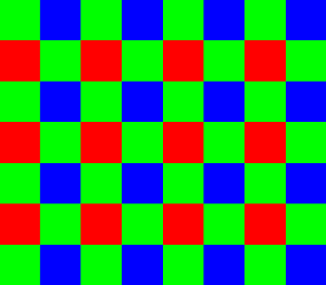
RGGB Mosaic
The CFA Encoding Task takes a RGBA/BGRA stream and converts it to the CFA scheme color space. The output is a 16bit (RAW10,RAW12,RAW16) or 32bit(RAW20,RAW24)
The color filters are defined as follows:
Parameters & Attributes
Parameter Name |
Description |
Value Type |
Value Range |
Default Value |
Example |
|---|---|---|---|---|---|
colorFilterArrayFlipHorizontal |
Dependent on the read direction the image has to flipped horizontally |
boolean |
0,1 |
0 |
0 |
colorFilterArrayFlipVertical |
Dependent on the read direction the image has to flipped vertically |
boolean |
0,1 |
0 |
0 |
colorFilterArrayCfaCf00 |
Calculation of the CF00 by (R,G,B) |
float[3] |
full range |
N.A. |
(1, 0, 0) |
colorFilterArrayCfaCf01 |
Calculation of the CF01 by (R,G,B) |
float[3] |
full range |
N.A. |
(0, 1, 0) |
colorFilterArrayCfaCf10 |
Calculation of the CF10 by (R,G,B) |
float[3] |
full range |
N.A. |
(0, 1, 0) |
colorFilterArrayCfaCf11 |
Calculation of the CF11 by (R,G,B) |
float[3] |
full range |
N.A. |
(0, 0, 1) |
colorFilterArrayCfaSemantic |
|
string |
N.A. |
||
colorFilterArrayMaximalValue |
If the input is normalized to 1: maximal value of output Else: a linear multiplier to the output |
uint64 |
full range |
N.A. |
16777215 |
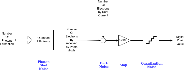
Sensor Noise#
Introduction
Noise is a common problem in image sensors. This tasks adds the dynamic noises to the image, photon shot noise and dark shot noise. The photon noise is modeled as a Poisson distribution. The dark shot noise is modeled as a Gaussian distribution. This task doesn’t simulate any spatial noise effects, like fixed pattern noise, photo response non-uniformity (PRNU) or dark signal non-uniformity (DSNU).
The noise model could be seen as the following transfer function
Parameters & Attributes
Parameter Name |
Description |
Value Type |
Value Range |
Default Value |
Example |
|---|---|---|---|---|---|
noiseDarkShotNoiseGain |
Gain applied of the dark noise generated |
float |
full range |
N.A. |
10 |
noiseDarkShotNoiseSigma |
The sigma of the normal distribution noise randomizer |
float |
full range |
N.A. |
0.5 |
noiseHdrCombinationData |
Specification of the gains and offsets to simulate different HDR zones |
float2 array |
full range |
N.A. |
[(5.8, 4000), (58, 8000), (70, 16000)] |
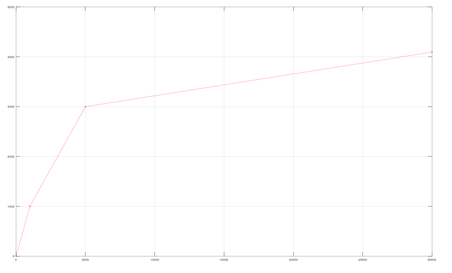
Companding#
Introduction
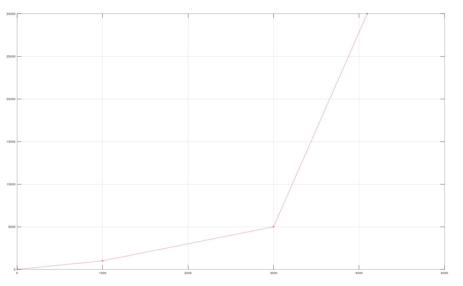
Internally, an HDR image sensor works with 20 bit or 24 bit precision. To transmit the data, the pixels are compressed/companded by a piece-wise-linear function to the output format (e.g. RAW8, RAW10, RAW12, RAW16).
Here is a simple example of a PWL companding function to RAW12:
Parameters & Attributes
Parameter Name |
Description |
Value Type |
Value Range |
Default Value |
Example |
|---|---|---|---|---|---|
compandingAlignment |
The alignment of the resulting raw value whereby LSB = 0 If the maximal PWL output value is greater than 65535, the output array will have uint32 pixels, else uint16 pixels. For example if the output is RAW12 and it should be aligned to the MSB of a 16bit value, you have to set it to 15 |
uint32 |
|
N.A. |
11 |
compandingPrePedestal |
A pedestal applied before the companding |
uint32 |
full range |
0 |
0 |
compandingPostPedestal |
A pedestal applied after the companding |
uint32 |
full range |
0 |
0 |
compandingLinearCompandCoeff |
The PWL companding coefficients
|
array of float[2] |
full range |
N.A. |
ISP#
Introduction
The Image Signal Processor (ISP) further processes the image from the sensor. The ISP is responsible for the decompression of the image values via a piece-wise-linear function (decompanding), conversion from color mosaic back to pixel colors (demosaicing), and other operations like denoising and colorspace conversion.
Parameters & Attributes
Parameter Name |
Description |
Value Type |
Value Range |
Default Value |
Example |
|---|---|---|---|---|---|
ispSmodelCameraProgram |
A base64 encoded ISP program for use on an NVIDIA Orin ISP. |
string |
base 64 values |
N.A. |
1 |
ispSmodelRawDataPaddingMode |
Raw data padding mode for ISP processing. |
string |
|
NONE |
“NONE” |
ispSmodelSensorRawFormat |
Sensor raw format for ISP processing. |
string |
|
RAW8 |
“RAW12” |
Introspection (Debugging)#
Introduction
The API defining these options is not stable. The options may change in future releases.
In addition to the “OmniCameraSensorPreIsp” and “OmniCameraSensorPostIsp”, other AOVs can be requested to inspect the simulation pipeline. * OmniCameraSensorInputSource : The input image to the simulation pipeline. * OmniCameraSensorPostColorCorrection : The input image with color correction applied. * OmniCameraSensorPostCfa : The color corrected image with color filter array processing applied. * OmniCameraSensorPostNoise : The color filter array image with noise applied. * OmniCameraSensorPreIsp : The noise image prepared for ISP processing, after companding. * OmniCameraSensorPostYuvIsp : The ISP output image in AYUV color space.
Some options are provided to inspect the simulation pipeline. This includes file input and output. When input files are read, any input images from previous operations are ignored and the file input is used instead.
Parameters & Attributes
Parameter Name |
Description |
Value Type |
Value Range |
Default Value |
Example |
|---|---|---|---|---|---|
introspectionOutputFile |
Enable file saving. |
boolean |
0,1 |
false |
1 |
introspectionOutputFileDirectory |
The output location for image buffers. Required to enable file output. |
string |
valid path |
N.A. |
“/dir/” |
introspectionOutputFileEachFrameOneFile |
If true, each subsequent rendered frame is output to a separate file with an increasing index number name. Otherwise, frames are concatenated into a single file. |
boolean |
0,1 |
N.A. |
1 |
introspectionOutputFileOnlyLastFrame |
If true, only the most recent frame is saved. Otherwise, all frames are saved. Requires introspectionOutputFileEachFrameOneFile to be enabled. |
boolean |
0,1 |
N.A. |
1 |
introspectionOutputViz |
Enable texture viewing in the Sensor Visualizer panel. |
boolean |
0,1 |
false |
1 |
introspectionOutputVizInputChannel |
Channel for input texture visualization. |
int |
full range |
101 |
101 |
introspectionOutputVizRawChannel |
Channel for RAW texture visualization. |
int |
full range |
102 |
102 |
introspectionOutputVizOutputChannel |
Channel for output texture visualization. |
int |
full range |
103 |
103 |
introspectionInputRaw |
Inject a RAW input file that will be processed by the ISP. If set, any input images from previous operations are ignored and the file input is used instead. |
boolean |
0,1 |
false |
1 |
introspectionInputRawPath |
The path to a raw input file to be processed by the ISP. If set, any input images from previous operations are ignored and the file input is used instead. |
string |
valid path |
N.A. |
“/dir/input.raw” |
introspectionInputRawWidth |
The width of the input image. If set, any input images from previous operations are ignored and the file input is used instead. |
int |
full range |
N.A. |
1920 |
introspectionInputRawHeight |
The height of the input image. If set, any input images from previous operations are ignored and the file input is used instead. |
int |
full range |
N.A. |
1080 |
introspectionInputRawSkipFront |
The number of bytes to skip before each frame. If set, any input images from previous operations are ignored and the file input is used instead. |
int |
full range |
N.A. |
0 |
introspectionInputRawSkipBack |
The number of bytes to skip after each frame. If set, any input images from previous operations are ignored and the file input is used instead. |
int |
full range |
N.A. |
0 |
introspectionInputRawFileDataType |
The data type to which the data is converted to |
string |
|
N.A. |
“UINT8” |
introspectionInputRawLoop |
Indicates whether the input file shall be looped infinitely. |
boolean |
0,1 |
true |
1 |
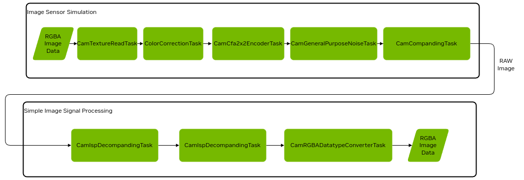
Camera Simulation in Omnigraph post processing#
The camera post processing is organized as a graph with task nodes defining the image transfer functions
Here is the full Omniverse Core API rendering pipeline:
Standard Inputs and Outputs#
All cameras task nodes beside special nodes have the following five standardized input pins:
Parameter |
Description |
Value |
Default |
|---|---|---|---|
inputs:rp |
The render product on which the CUDA computation is applied |
uint64 |
0 |
inputs:gpu |
The Omniverse GPU interface |
uint64 |
0 |
inputs:src |
The source buffer which consists of the image descriptor and the image buffer |
uint64 |
0 |
inputs:simTimeIn |
If the application provides a simulation time it’s passed by this parameter. |
double |
0.0 |
inputs:hydraTimeIn |
The hydra engine time, usually used to support animations |
double |
0.0 |
All cameras task nodes beside special nodes have the following five output pins:
Parameter |
Description |
Value |
Default |
|---|---|---|---|
outputs:rp |
The render product on which the CUDA computation is applied |
uint64 |
0 |
outputs:gpu |
The Omniverse GPU interface |
uint64 |
0 |
outputs:dest |
The destination buffer which consists of the image descriptor and the image buffer |
uint64 |
0 |
outputs:simTimeOut |
If the application provides a simulation time it’s passed by this parameter. |
double |
0.0 |
outputs:hydraTimeOut |
The hydra engine time, usually used to support animations |
double |
0.0 |
To connect two nodes you have to connect the output to the input pins:
Task1.outputs:rp -> Task2.inputs:rp
Task1.outputs:gpu -> Task2.inputs:gpu
Task1.outputs:dest -> Task2.inputs:src
Task1.outputs:simTimeOut -> Task2.inputs:simTimeIn
Task1.outputs:hydraTimeOut -> Task2.inputs:hydraTimeIn
Camera Tasks and their parameter settings#
CamTextureReadTaskNode#
Introduction
The CamTextureReadTaskNode is selecting the render product which is used to feed into the camera pipeline. Furthermore it initiates the descriptor on which successor graph nodes
You have to make sure that the render product was included into the requested RTX render products
- Currently the following render products are supported
Low Dynamic Range Image
High Dynamic Range Image
High Dynamic Range Image
Depth Map
Segmentation Map
Omnigraph Node Name
omni.sensors.nv.camera.CamTextureReadTaskNode
Parameters & Attributes
Parameter Name |
Description |
Value Type |
Value Range |
Default Value |
Example |
|---|---|---|---|---|---|
inputs:aov |
Determines which render AOV is used |
string |
|
LDR |
LDR |
ColorCorrectionTaskNode#
Introduction
To adapt to the color space and the dynamics of a real camera sensor this task applies a color correction, dynamic range limiting and constant white balance. With these parameters the user can consider items like exposure and color shift of image sensors.
Omnigraph Node Name
omni.sensors.nv.camera.ColorCorrectionTaskNode
Parameters & Attributes
Parameter Name |
Description |
Value Type |
Value Range |
Default Value |
Example |
|---|---|---|---|---|---|
inputs:fullwell_black |
The value range of the output from the black level value to saturation |
float |
full range |
1.0 |
|
inputs:black |
Black level |
float |
full range |
0.0 |
|
inputs:output_float16 |
Indicates whether the output shall be float16 or uint8_t |
boolean |
0,1 |
0 |
|
inputs:Rr |
Red to Red conversion |
float |
full range |
1.0 |
|
inputs:Rg |
Red to Green conversion |
float |
full range |
0.0 |
|
inputs:Rb |
Red to Blue |
float |
full range |
0.0 |
|
inputs:Gr |
Green to Red |
float |
full range |
0.0 |
|
inputs:Gg |
Green to Green |
float |
full range |
1.0 |
|
inputs:Gb |
Green to Blue |
float |
full range |
0.0 |
|
inputs:Br |
Blue to Red conversion |
float |
full range |
0.0 |
|
inputs:Bg |
Blue to Green conversion |
float |
full range |
0.0 |
|
inputs:Bb |
Blue to Blue conversion |
float |
full range |
0.0 |
|
inputs:redBlueSwap |
swaps the red and blue component (RGBA->BGRA or BGRA->RGBA) |
boolean |
0,1 |
0 |
|
inputs:whiteBalance |
Defines the general gain for each color component after the CCM, could also be used to scale the values to the image sensor’s digital number (DN) |
float3 |
full range |
[1.0, 1.0, 1.0] |
[0.8, 1.9, 1.3] |
inputs:applySaturation |
Indicates whether the saturation parameters should be applied |
boolean |
0,1 |
0 |
CamCfa2x2EncoderTaskNode#
Omnigraph Node Name
omni.sensors.nv.camera.CamCfa2x2EncoderTaskNode
Parameters & Attributes
Parameter Name |
Description |
Value Type |
Value Range |
Default Value |
Example |
|---|---|---|---|---|---|
inputs:flipHorizontal |
Dependent on the read direction the image has to flipped horizontally |
boolean |
0,1 |
0 |
0 |
inputs:flipVertical |
Dependent on the read direction the image has to flipped vertically |
boolean |
0,1 |
0 |
0 |
inputs:CFA_CF00 |
Calculation of the CF00 by (R,G,B) |
float[3] |
full range |
N.A. |
(1, 0, 0) |
inputs:CFA_CF01 |
Calculation of the CF01 by (R,G,B) |
float[3] |
full range |
N.A. |
(0, 1, 0) |
inputs:CFA_CF10 |
Calculation of the CF10 by (R,G,B) |
float[3] |
full range |
N.A. |
(0, 1, 0) |
inputs:CFA_CF11 |
Calculation of the CF11 by (R,G,B) |
float[3] |
full range |
N.A. |
(0, 0, 1) |
cfaSemantic |
|
string |
N.A. |
||
maximalValue |
If the input is normalized to 1: maximal value of output Else: a linear multiplier to the output |
uint64 |
full range |
N.A. |
16777215 |
CamGeneralPurposeNoiseTask#
Omnigraph Node Name
omni.sensors.nv.camera.CamGeneralPurposeNoiseTask
Parameters & Attributes
Parameter Name |
Description |
Value Type |
Value Range |
Default Value |
Example |
|---|---|---|---|---|---|
inputs:darkShotNoiseGain |
Gain applied of the dark noise generated |
float |
full range |
N.A. |
10 |
inputs:darkShotNoiseSigma |
The sigma of the normal distribution noise randomizer |
float |
full range |
N.A. |
0.5 |
inputs:hdrCombinationData |
Specification of the gains and offsets to simulate different HDR zones |
float2 array |
full range |
N.A. |
[(5.8, 4000), (58, 8000), (70, 16000)] |
Companding#
Omnigraph Node Name
omni.sensors.nv.camera.CamCompandingTaskNode
Parameters & Attributes
Parameter Name |
Description |
Value Type |
Value Range |
Default Value |
Example |
|---|---|---|---|---|---|
inputs:Alignment |
The alignment of the resulting raw value whereby LSB = 0 If the maximal PWL output value is greater than 65535, the output array will have uint32 pixels, else uint16 pixels. For example if the output is RAW12 and it should be aligned to the MSB of a 16bit value, you have to set it to 15 |
uint32 |
|
N.A. |
11 |
inputs:PrePedestal |
A pedestal applied before the companding |
uint32 |
full range |
0 |
0 |
inputs:PostPedestal |
A pedestal applied after the companding |
uint32 |
full range |
0 |
0 |
inputs:LinearCompandCoeff |
The PWL companding coefficients
|
array of float[2] |
full range |
N.A. |
Decompanding#
Introduction
Decompanding is the decompression of the image values via a piece-wise-linear (PWL) function.
Here is a simple example of the PWL decompanding of the function which has been shown in CamCompandingTaskNode:
Omnigraph Node Name
omni.sensors.nv.camera.CamIspDecompandingTaskNode
Parameters & Attributes
Parameter Name |
Description |
Value Type |
Value Range |
Default Value |
Example |
|---|---|---|---|---|---|
inputs:LinearCompandCoeff |
The PWL decompanding coefficients
|
array of float[2] |
full range |
N.A. |
1 |
inputs:PostPedestal |
A pedestal applied before the decompanding |
uint |
full range |
N.A. |
0 |
inputs:PrePedestal |
A pedestal applied after the decompanding |
uint |
full range |
N.A. |
0 |
inputs:Alignment |
The alignment of the companded RAW value (see description in CamCompandingTaskNode) |
uint |
|
N.A. |
11 |
inputs:ConvertTo16bit |
The data type to which the data is converted to |
boolean |
0,1 |
N.A. |
1 |
ISP RGGB Demosaicing#
Introduction
This tasks converts CFA images which use common Red, Green, Blue color filters to RGBA images.
Omnigraph Node Name
omni.sensors.nv.camera.CamIspRGGBDemosaicingTaskNode
Parameters & Attributes
Parameter Name |
Description |
Value Type |
Value Range |
Default Value |
Example |
|---|---|---|---|---|---|
inputs:bayerGrid |
Indicates which RGGB demosaicing should be applied |
string |
|
N.A. |
“RGGB” |
inputs:outputFormat |
The data type to which the data is converted to |
string |
N.A. |
“UINT8” |
RGBADatatypeConverter#
Introduction
This task provides a simple image type conversion. No sophisticated tonemapping is applied, just a simple one which could result in loosing image structures
Omnigraph Node Name
omni.sensors.nv.camera.CamRGBADatatypeConverterTaskNode
Parameters & Attributes
Parameter Name |
Description |
Value Type |
Value Range |
Default Value |
Example |
|---|---|---|---|---|---|
inputs:uintApplyGammaCorrection |
Indicates whether a gamma correction should be applied |
boolean |
0,1 |
N.A. |
1 |
inputs:rgbaDataType |
The data type to which the data is converted to |
float |
|
N.A. |
“UINT8” |
Depth Camera Sensor#
A depth camera sensor is a device to measure the distance from the sensor to objects in the scene, often using stereo disparity or projector time-of-flight.
Unlike the sensor and ISP simulation, the depth camera sensor simulation is not implemented as an Omnigraph pipeline. Instead, it is a post process operation in the renderer.
Single View Depth Camera#
This depth camera sensor model uses a single camera view to simulate a stereo camera pair and compute disparity and depth. Depth values from the rendering process are converted to disparity, which is then used to reproject the depth from the left imager position to the right imager position. This leaves gaps in regions that are occluded from both imagers.
To simulate disparity noise, a Gaussian noise model is applied to the disparity samples. The disparity samples are quantized to pixel steps of the noise mean size, then randomized according to the sigma deviation curve. The randomness for the deviation is different each frame, resulting in temporal and spatial noise in the output depth.
A confidence map is also generated to indicate the reliability of the depth values. The confidence map is created from a Sobel edge detection operation applied to the input color image. The Sobel result is saturated to 0-1 and then scaled by the confidence threshold to create the confidence map. Depth values with a confidence below the threshold are discarded.
USD Schema The depth camera sensor can be enabled by adding the OmniSensorDepthSensorSingleViewAPI class to the RenderProduct. Documentation for the schema can be found in the schema file.
Example usage:
def RenderProduct "CameraDepthSingleView"(
    prepend apiSchemas = ["OmniSensorDepthSensorSingleViewAPI"]
)
{
    bool omni:rtx:post:depthSensor:enabled = 1
    float omni:rtx:post:depthSensor:baselineMM = 75.0
    float omni:rtx:post:depthSensor:focalLengthPixel = 897.0
    float omni:rtx:post:depthSensor:sensorSizePixel = 1280.0
    float omni:rtx:post:depthSensor:maxDisparityPixel = 150.0
    float omni:rtx:post:depthSensor:confidenceThreshold = 1.0
    float omni:rtx:post:depthSensor:noiseMean = 0.25
    float omni:rtx:post:depthSensor:noiseSigma = 0.25
    float omni:rtx:post:depthSensor:noiseDownscaleFactorPixel = 1.0
    float omni:rtx:post:depthSensor:minDistance = 0.5
    float omni:rtx:post:depthSensor:maxDistance = 9999.9
    int omni:rtx:post:depthSensor:rgbDepthOutputMode = 3

    rel camera = </Camera>
    rel orderedVars = [
      </Render/Vars/depthSensorDepth>,
      </Render/Vars/depthSensorPointCloudDepth>,
      </Render/Vars/depthSensorPointCloudColor>,
      </Render/Vars/DepthSensorImager>,
      </Render/Vars/ldrColor>
    ]
    uniform int2 resolution = (1280, 720)
}
Output AOVs
AOV Name |
Format |
Description |
|---|---|---|
DepthSensorDistance |
Float32 |
Distance in meters |
DepthSensorPointCloudPosition |
RGBAFloat32 |
X,Y,Z positions in meters relative to the left imager camera |
DepthSensorPointCloudColor |
RGBAUnorm8 |
Color for each point cloud point |
DepthSensorImager |
Float32 |
Left imager LDR luminance |
Parameters
Parameter Name |
Value Type |
Range |
Default Value |
Description |
|---|---|---|---|---|
Baseline |
float |
Full range |
55.0 |
The distance in mm between the simulated cameras. Larger positive/negative values will increase the ‘unknown’ black/hole regions around objects where the cameras cannot see. |
Focal Length |
float |
Positive values |
897.0 |
Simulated focal length of the camera in pixel units. This does not match the Camera prim focal length. Combined with the Sensor Size setting, this sets the field of view for the disparity calculation. Since the actual FOV is controlled on the camera prim, this only adjusts the amount of left/right disparity. Lower focal length decreases disparity. |
Sensor Size |
float |
Positive values |
Sets width of the sensor in pixel units. This does not match the actual RenderProduct pixel size! Combined with Focal Length, this affects the amount of disparity. Higher values decrease disparity. |
|
Max Disparity |
float |
Positive values |
Sets the maximum number of disparity pixels. Higher values allow the sensor to resolve closer (more disparate) objects. Lower values reduces the depth sensing range. |
|
Disparity Noise Mean |
float |
Full range |
0.5 |
Controls the quantization factor for the disparity noise, in pixels. Higher values reduce depth resolution. |
Disparity Noise Sigma |
float |
Full range |
1.0 |
Controls the variation in the disparity noise. Higher values make depth values vary wider across the quantization (noise mean) range. |
Disparity Noise Downscale |
float |
1.0 - 10.0 |
1.0 |
Sets the coarseness of the disparity noise in pixels. Higher values reduce the spatial resolution of the noise. |
Disparity Confidence |
float |
Positive values |
0.9 |
Controls how likely a depth sample is considered valid. Lower values result in more depth values from smooth surfaces being rejected. |
Outlier Removal |
boolean |
True or False |
True |
Filter out single pixel samples caused by antialiasing jitter and reprojection resolution. |
Min Distance |
float |
Positive values |
0.5 |
Convenience setting for setting the minimum range cutoff. This does not model real sensor parameters. Also adjusts the gradient for the grayscale and rainbow depth visualizations. |
Max Distance |
float |
Greater than Min Distance |
10.0 |
Convenience setting for setting the maximum range cutoff. This does not model real sensor parameters. Also adjusts the gradient for the grayscale and rainbow depth visualizations. |
RGB Depth Output Value |
int |
0 - 7 |
1 |
Overrides the LDRColor buffer with a debug visualization. The grayscale and rainbow options are similar to RealSense visualizations. 0 - Pass through LDRColor 1 - Repeated 1 meter grayscale gradient 2 - Grayscale gradient over min/max distance 3 - Rainbow gradient over min/max distance 4 - Input Depth values in grayscale 5 - Reprojected depth with confidence culling applied 6 - Confidence Map with Disparity 7 - Disparity values in grayscale |
Show Distance |
boolean |
false |
Prints a debug value of the center distance in meters to the console. |