Manual
Install Instructions
Please install the ParaView Connector plugin via the Omniverse Launcher, which will guide you through installing the connector plugin to your local ParaView install.
On Windows, it will ask for the location of an existing official ParaView install into which to copy the plugin
On Linux, make sure to call
export PVOV_INSTALL_PATH=<ParaView-install-dir>before running the Omniverse Launcher, which will point the installer to the right location
Follow our Connector installation instructions for details. In case of issues, they should appear in the notification section of the Omniverse Launcher.
On a headless Linux system, installing the ParaView Connector can be done manually using the ParaView Connector launcher install from a different machine:
Locate the ParaView Connector installation, typically at
~/.local/share/ov/pkg/paraview-connector-<version-nr>, and copy it over to the target machine.Manually run
ParaViewOmniSetup.sh -iafter settingPVOV_INSTALL_PATHto your PV installation directory.Or, just copy the /lib folder over to the PV install, and add the following line to
<PVOV_INSTALL_PATH>/lib/paraview-<version-nr>/plugins/paraview.plugins.xml:<Plugin name="OmniverseConnector" auto_load="1" />
Note
You can verify whether the ParaView Connector is properly installed by running ParaView and navigating to Tools->Manage Plugins, and making sure the Omniverse Connector plugin is loaded.
User Interface
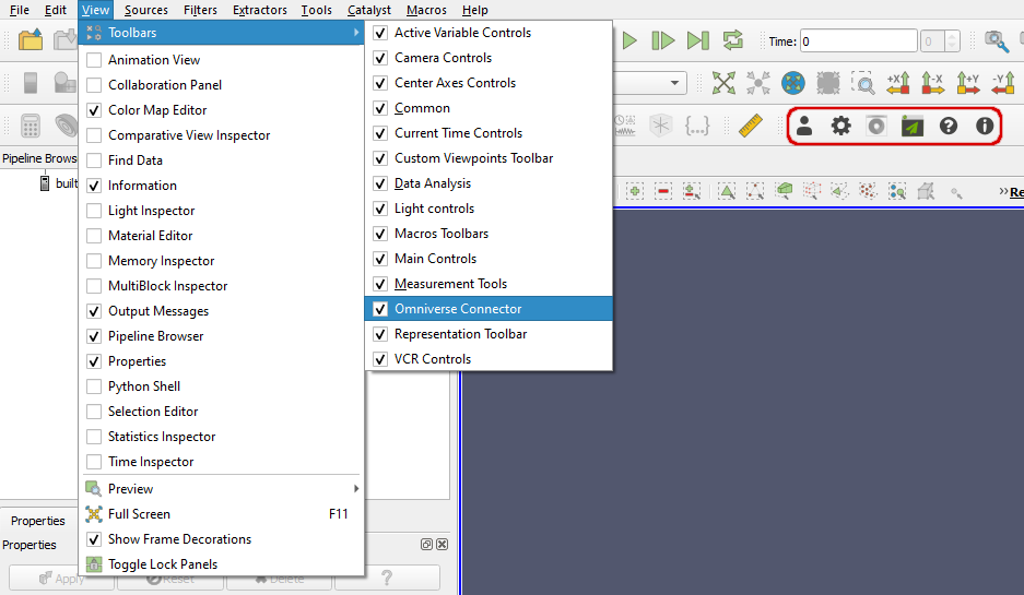
Once the Plugin has been installed, you should find the Omniverse Toolbar is already in place (highlighted in red below). If not, just enable the option under View->Toolbars->OmniverseConnector.
Before creating an Omniverse Connector render view, it is recommended to at least familiarize yourself with the Sign-In and Settings menus. The following sections briefly explain the function of each button:
Sign-In
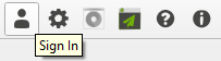
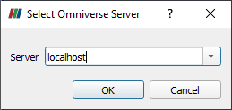
If output to a NVIDIA Omniverse™ Nucleus server is desired, signing in is required before opening an Omniverse Connector render view. The sign-in dialog allows users to connect to their Omniverse Nucleus server for mounts. Simply enter your Omniverse Nucleus ‘User Name’ and ‘Password’:
Setting |
Result |
|---|---|
Server |
Address of an NVIDIA Omniverse™ Nucleus server.
|
OK |
Initiates the connection with selected user and server.
|
Cancel |
Stops the sign-in process and closes the sign-in window.
|
Settings
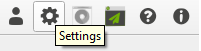
The settings menu is the main hub for changing the Omniverse Connector plugin’s parameters, and will be applied to the next Omniverse Connector render view that is opened. Therefore, its also automatically launched right before an Omniverse Connector render view is created, to allow for last-minute adjustments to be made.
Most often, the settings menu is used to browse for an output location where the USD files have to be written to. A detailed description of each setting is provided in the Settings Menu Explained section.
Note
Although the options within the settings menu cannot be changed for an active Omniverse Connector render view, there are properties which can be changed at any time. Go to Omniverse Connector View Properties to find out which options this applies to.
Live Synchronization
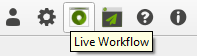
Pressing this button creates a special layer on the Nucleus server, which can be opened in Omniverse USD Composer (using for example the Open View In Omniverse App button), after which changes to any existing ParaView pipeline nodes will automatically be propagated to the rendered scene in Omniverse USD Composer.
For details on what ParaView operations the live functionality is limited to, see the Live Synchronization Details section.
Note
This only works when the output directory resides on a Nucleus server
Open View In Omniverse App
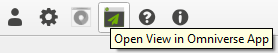
Once an Omniverse Connector render view has been created, this button opens the contents of the currently active view directly an Omniverse application of choice. For this to work, set up your desired Omniverse application (such as Omniverse USD Presenter or Omniverse USD Composer) in the settings menu. Afterwards, simply click the ‘Open View in Omniverse App’ button and the Omniverse application will launch with your visualization loaded and ready to go.
Help
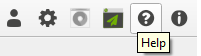
Launches your default web browser to the NVIDIA Omniverse™ ParaView Connector Documentation.
About
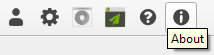
Opens a dialogue and displays version information about the installed NVIDIA Omniverse™ ParaView Connector, and provides helpful links to access release notes and to get support.
Test the connector using the ParaView wavelet source
This section will walk through a very simple example using one of ParaView’s built-in data sources to demonstrate the connector in action. The steps outlined below assume that the connector plugin is installed, enabled, and configured to output to a desired location (on a Omniverse Nucleus server or otherwise).
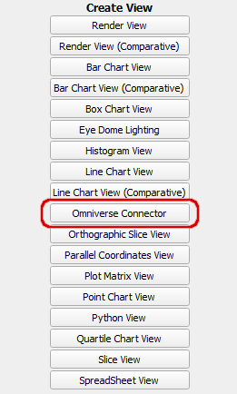
Create an ‘Omniverse Connector’ render view,
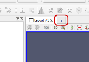
by clicking the ‘+’ tab and choosing Omniverse Connector:
Note
The Omniverse Connector render view is the view which outputs to the Omniverse server. If you do not want your local view changes to propagate to Omniverse, simply use another view in ParaView instead. Remember that the default view when ParaView starts up is a regular render view which does not output to USD or communicate with Omniverse at all.
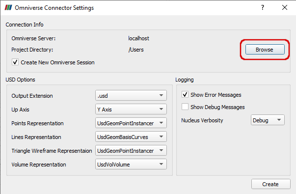
In the settings panel that pops up, use the ‘Browse’ button to select an output destination on a Nucleus server (no local disk):
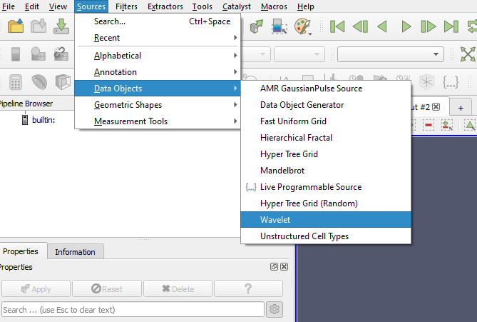
Add a ‘wavelet’ source and activate it with ‘Apply’.
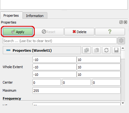
Make some isosurfaces using the contour filter:
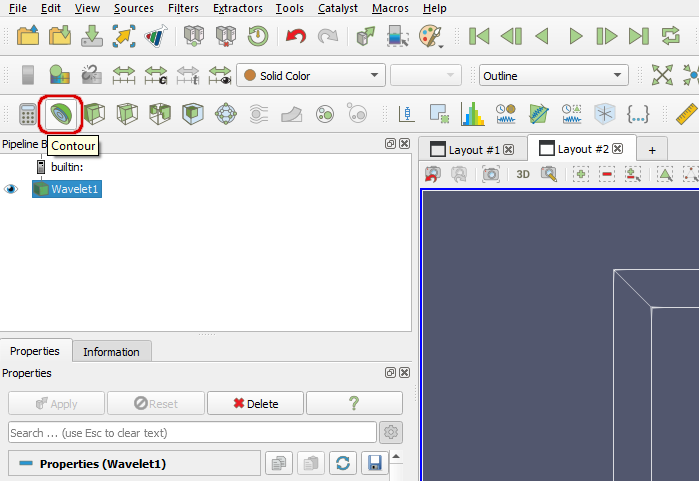
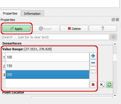
Set the isovalues to 100, 150, and 200, and click Apply:
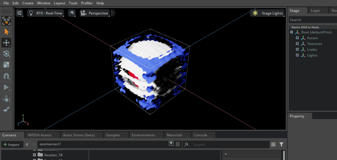
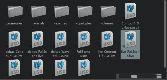
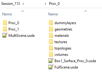
In Omniverse USD Composer, navigate to your configured ParaView session, and open ‘FullScene.usd’.
Note
You can install and launch Omniverse Composer from the Omniverse Launcher, or alternatively with the Open View In Omniverse App button.
After opening and zooming in slightly, the output in Omniverse USD Composer looks like this:
Any changes to the contour node in ParaView, such as changing the isovalues, will not automatically show up in Create. For that to happen, live synchronization has to be enabled. This can be done by clicking the Live Synchronization button in ParaView’s Omniverse toolbar, and opening live_FullScene.live in Create (or clicking the Open View In Omniverse App button once more):
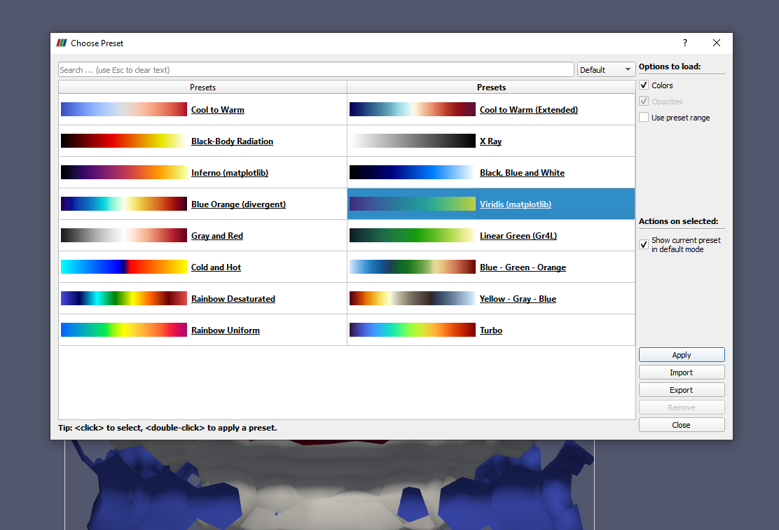
Change the color map in ParaView and see the colors update in Omniverse USD Composer:
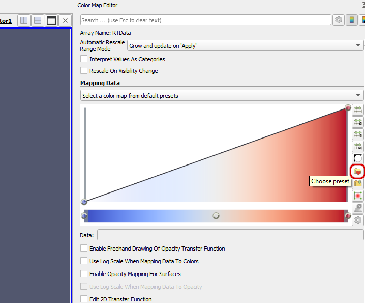
Note
If you cannot see the Color Map Editor, enable it in the ‘View’ menu.
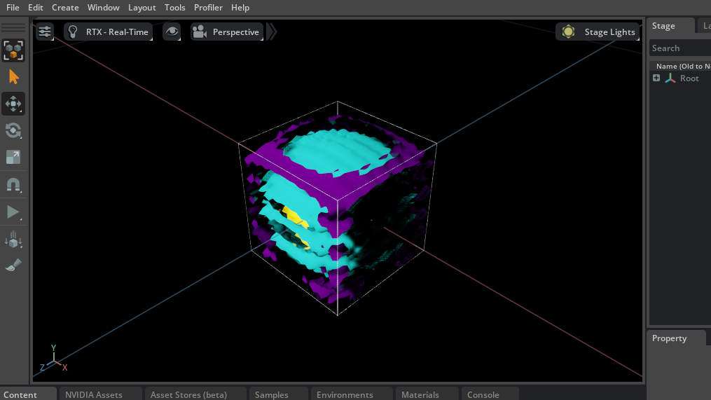
The result in Omniverse USD Composer:
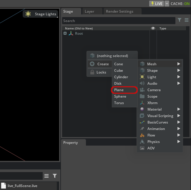
Add a Plane in Omniverse USD Composer using the Stage UI panel, by right-clicking and choosing ‘Create->Mesh->Plane’:
the plane can be moved up and down along the Y axis using the ‘Move’ widget in Omniverse USD Composer, by dragging that particular axis:

And that’s it! Now you can enjoy using ParaView with Omniverse to do new and interesting things with your data, and do so collaboratively in real time.
Live Synchronization Details
With live synchronization enabled, a user can apply modifications in ParaView to existing pipeline nodes and see the result of those changes in Omniverse client applications such as Omniverse USD Composer, without reloading the scene. After pressing the Live Synchronization button, the ParaView Connector generates a separate layer called live_FullScene.live within its output directory. Opening this layer as a stage in Omniverse USD Composer will allow synchronization to take place. For convenience, the Open View In Omniverse App will do this automatically when live synchronization is enabled. An example of its usage provided in Test the connector using the ParaView wavelet source.
Any operations that will result in new or deleted layers in the USD output will not work with live synchronization. Examples of this are creating or deleting a ParaView pipeline node, or enabling/disabling the output of 3D viewport widgets in the Properties panel. Technically live synchronization will remain enabled, but operations performed afterwards may not propagate to client applications anymore. As it is not obvious when such operations are performed, one can set ParaView’s logging output to Show Debug Messages in the Logging section of the Settings menu (see Omniverse Connector Render View Settings). A warning will appear every time an operation is performed that could break live synchronization.
Volumes and OpenVDB
One important feature of the ParaView Connector is its ability to convert structured volume data to OpenVDB. For this to happen, one simply opens a structured volume in an Omniverse Connector render view, such as the wavelet example from the previous section. Set its representation to ‘Volume’, and the connector will automatically generate an OpenVDB file in the volumes/ subdirectory of the output location.
The OpenVDB file is referenced from within USD and therefore could be used in combination with the complete stage, or just on its own by loading it into any application supporting the file format.
There are a number of possible ways to output data to OpenVDB depending on your usecase:
Direct output of the source field array used for coloring, with optionally any related field arrays.
Preclassified output, ie. the result of applying the transfer function to the source field array, resulting in colors and opacities
Mesh-based output compatible with Omniverse USD Composer
The various options are explained in more detail in the following sections.
Direct Source Field Array Output
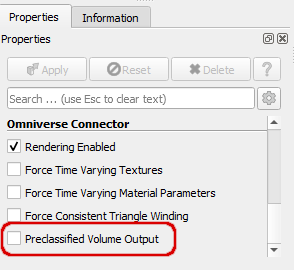
If the property Preclassified Volume Output in Omniverse Connector View Properties is disabled:
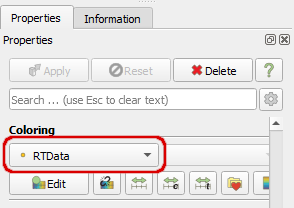
In this case, the OpenVDB output will consist of a single grid named density, containing the data array used as input for ParaView’s volume rendering, highlighted in red in the following image:
Supported types include float/double(3) or int/long types. Byte and short types will be normalized to float data, with double arrays converted to float as well.
If an Omniverse Pass Arrays filter is used, all selected field arrays will be included into the OpenVDB, with their grid names equal to their field array names. No density array will be written. Conversion from double to float is optional, but normalization of byte and short types to float will remain. Only those selected field arrays which have the same layout (cell or point) as the source field array used for coloring in ParaView will be included into the OpenVDB.
Preclassified Output
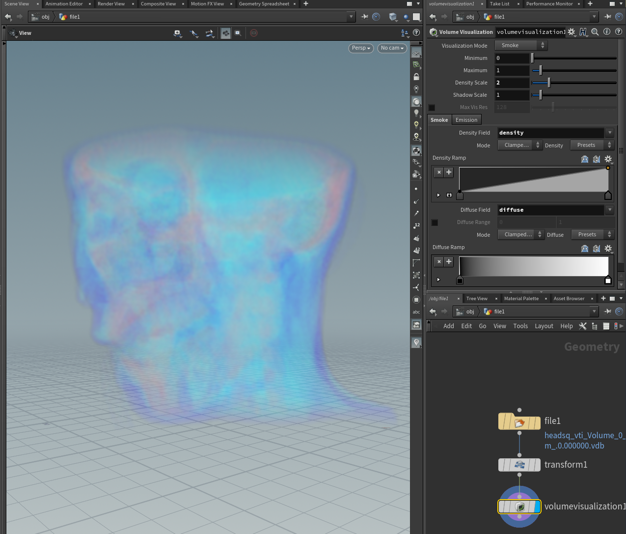
If Preclassified Volume Output is set to true, ParaView’s transfer function will be applied to this data before it is written out to OpenVDB. The resulting colors and opacities (of float type) will be contained in separate grids called diffuse and density respectively. The following image shows Houdini rendering the OpenVDB output created by the Omniverse Connector on the ‘headsq.vti’ example dataset.
Mesh-based Output Compatible With Omniverse USD Composer
Because Omniverse USD Composer does not directly support rendering UsdVolVolume prim with OpenVDBAsset fields, the Omniverse Connector Render View Settings allows for the volume representation to be changed to a textured UsdGeomMesh with corresponding MDL material:
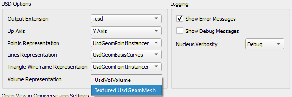
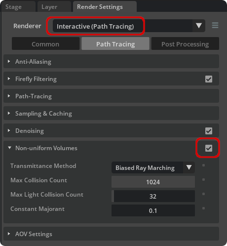
This can be loaded into Omniverse USD Composer, and rendered by setting the renderer to ‘Path Tracing’ and enabling ‘Non-uniform Volumes’. This is highlighted in red by the following image:
Working With Material Graphs
The materials output by the ParaView Connector are compatible with Omniverse USD Composer material graphs. Effectively, it means that the material’s USD prim nodes coming from the ParaView Connector are recognized by the material graph editor, and the inputs of those materials can be driven by any of the geometry data (primvars) present in geometry to which the material is connected.
A basic example of how to use this functionality is presented in the following tutorial.
In case of the ParaView Connector, the most common use case is to drive a color or transparency material input using an arbitrary field array from the Omniverse Pass Arrays filter (see Overview). Specifically, the filter is used to add the particular field array to the geometry’s USD output, allowing us to select this array in Omniverse USD Composer as input to a material property - after the ParaView output has already been completed.
As an example, let’s assume a ParaView node has a point field array called Pres. Then the following steps show a possible way to connect it to the color input of a colormapped material:
Start with the output of an already colormapped geometry in ParaView Connector, with a colormap of choice and arbitrary input field. Also, the Pass Arrays filter has to be attached to the ParaView pipeline node, to allow the Pres field array to be propagated into the geometry’s USD output.
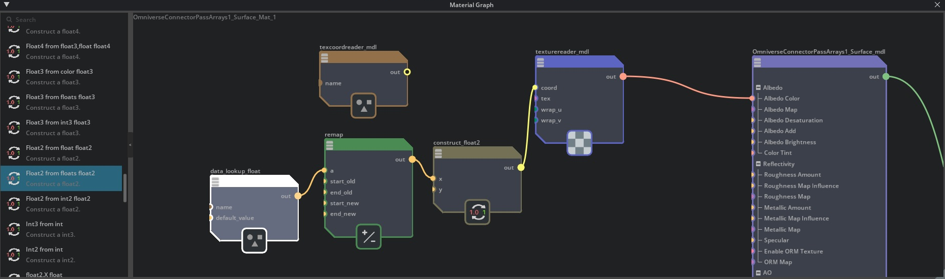
After opening the geometry’s material in the material graph editor in Omniverse USD Composer, add the node ‘Constants, state and primvars’ → ‘Primvar lookup float’ with the name attribute set to pv_point_Pres. In case of doubt, inspect the connected geometry’s raw USD properties in Omniverse USD Composer to find the appropriate primvar name.
Add the node ‘Math functions’ → ‘Remap float’ with start_old to the minimum, end_old to the maximum of the array’s value range. Set start_new to 0.0 and end_new to 1.0.
Finally, add ‘Constructors….’ → ‘Float2 from floats float2’ with the y variable set to 0.5.
Connect the nodes as shown in the image below, and finally to the coord input of the texturereader_mdl node.
Note
In Omniverse USD Composer, this functionality is limited to work only with particular surface geometries, see the Materials section in Known Issues.
Materials For Point-based Geometry
Output of colored points in Omniverse USD Composer is currently only possible using the UsdGeomPoints primitive in USD. To enable it, you have to:
Make sure to select UsdGeomPoints as Points Representation at creation time of the view (see Omniverse Connector Render View Settings)
Disable Interpolate scalars before mapping in the left-hand Properties panel once you’ve loaded the dataset.
That way, vertex coloring will be enabled and the ParaView Connector will export a custom mdl that adds color support in Omniverse USD Composer.
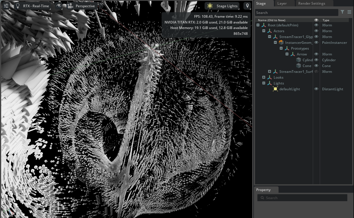
Glyphs
In ParaView, glyphs can be created in two different ways: either by adding a Glyph filter to the pipeline, or by enabling the 3D Glyphs representation in the left-hand side Properties panel. If using a filter, the ParaView Connector loses any glyph information and will output a collection of non-instanced triangles, severely increasing the memory profile and transfer duration of the generated USD output. When using the 3D Glyphs representation instead, the ParaView Connector outputs a UsdGeomPointInstancer to produce instanced shapes and thereby minimizing the amount of generated data, while keeping the original source data intact.
Only shapes resulting in instanced 3D meshes are supported, see Features for an up-to-date list.
Note
In Omniverse USD Composer, rendering color information for the glyph representation’s UsdGeomPointInstancer output is currently not supported, see Known Issues.
Usage with Python
The ParaView Connector supports python environments such as a pvpython or state loading within the ParaView GUI. Typically, the Connector is set up in the following manner:
from paraview.simple import *
pxm = paraview.simple.servermanager.ProxyManager()

# Change settings values
omnisettings = pxm.GetProxy('OmniConnectProxyGroup', 'OmniConnectSettings')
omnisettings.SetPropertyWithName('OutputLocal', 1)
omnisettings.SetPropertyWithName('LocalOutputDirectory', '/home/user/output')
omnisettings.SetPropertyWithName('OutputExtension', '.usd')

# An Omniverse Connector render view must be created
newRV = CreateView('OmniConnectRenderView')
SetActiveView(newRV)
Render()
If you want to load the python code as a ParaView state file from the GUI, a slightly modified template has to be used:
from paraview.simple import *
paraview.simple._DisableFirstRenderCameraReset()
pxm = paraview.simple.servermanager.ProxyManager()

# Change settings values
omnisettings = pxm.GetProxy('OmniConnectProxyGroup', 'OmniConnectSettings')
omnisettings.SetPropertyWithName('OutputLocal', 1)
omnisettings.SetPropertyWithName('LocalOutputDirectory', '/home/user/output')
omnisettings.SetPropertyWithName('OutputExtension', '.usda')

# An Omniverse Connector render view must be created
layout2 = CreateLayout(name='Layout #2')
SetActiveView(None)
newRV = CreateView('OmniConnectRenderView')
AssignViewToLayout(view=newRV, layout=layout2, hint=0)
Any items attached to the view using Show(item, newRV, ...) will be sent to Omniverse once newRV.Update() is called.
For an overview of the options that can be changed, consult the following list:
'OmniverseServer'->string
'OmniverseWorkingDirectory'->string
'LocalOutputDirectory'->string
'OutputLocal'->boolean
'CreateNewOmniverseSession'->boolean
'OutputExtension'->enum
'UpAxis'->enum
'PointsRepresentation'->enum
'LinesRepresentation'->enum
'TriangleWireframeRepresentation'->enum
'VolumeRepresentation'->enum
'ShowErrorMessages'->boolean
'ShowDebugMessages'->boolean
'NucleusVerbosity'->enum
where boolean values are 0 or 1 and enum values are simple zero-based integers aligning with their respective values in the dropdown list of the UI.
Note
The parameter OutputLocal determines whether the OmniverseWorkingDirectory is chosen for output (if false), or the LocalOutputDirectory (if true)
MPI environments
The ParaView Connector automatically detects when it is part of an MPI-enabled server process. In those cases, every server process will output its data to a separate subdirectory within the USD output directory. An additional multiscene USD file will be generated, combining the scene USD files from the separate process subdirectories as follows:
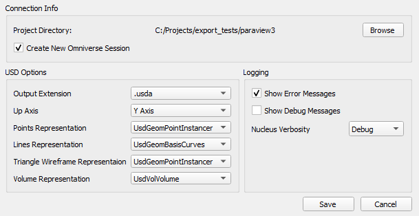
Settings Menu Explained
A detailed overview of all the options in the settings menu follows here:
Omniverse Connector Render View Settings
This is where users can set a directory to save USD scene files for visualization later. The settings will be applied at creation of an Omniverse Connector render view, and cannot be changed once such a render view has already been created.
Additionally, the ‘Properties’ panel on the left-hand side of the ParaView GUI is expanded with an ‘Omniverse Connector’ section, where you can find additional settings which can be changed while an Omniverse Connector render view has been created (see Omniverse Connector View Properties).
Element |
Result |
|---|---|
Project Directory |
USD scene files output directory.
|
Browse |
Open a dialog to change the ‘Project Directory’.
|
Create New Omniverse Session |
Create a new Omniverse Session directory every time an Omniverse Connector render view is opened. When disabled, the directory with the highest session number will be re-opened and work will continue within that existing scene.
|
Output Extension |
Choose whether USD output should be binary (.usd) or text-based (.usda).
|
Up Axis |
Select which axis is chosen as the up axis in the USD output.
|
Points Representation |
Choose the representation of points in USD: either use the UsdGeomPointInstancer or the UsdGeomPoints prim.
|
Lines Representation |
Choose the representation of lines in USD: either use the UsdGeomBasisCurves prim (curves) or UsdGeomPointInstancer with cylinders (sticks).
|
Triangle Wireframe Representation |
Choose the representation of wireframe triangle meshes in USD: either use the UsdGeomBasisCurves prim (curves) or UsdGeomPointInstancer with cylinders (sticks).
|
Volume Representation |
Choose the representation of volumes in USD: either use the UsdVolVolume prim with OpenVDBAsset fields, or a textured UsdGeomMesh with corresponding MDL material. The latter is more compatible with Omniverse USD Composer.
|
Show Error Messages |
Show Omniverse error messages.
|
Show Debug Messages |
Show Omniverse debug messages.
|
Nucleus Verbosity |
Set the verbosity of messages generated by Nucleus, with ‘Debug’ as most verbose. Requires ‘Show Debug Messages’ to be enabled.
|
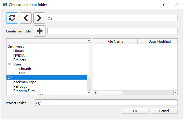
The below dialog is displayed when users click on the ‘Browse’ button.
Element |
Result |
|---|---|
Refresh |
Updates the window with latest data.
|
Left/Right |
Moves through the current directory structure in a step by step fashion.
|
Create New Folder |
Creates a new directory at current file path.
|
Left Pane |
Lists NVIDIA Omniverse™ Nucleus directories (if logged-in) and local drives / directories.
|
Right Pane |
Lists files in currently selected directory.
|
Project Folder |
The location and name of the project to create.
|
OK |
Save the selected folder as project directory.
|
Cancel |
Closes the dialogue.
|
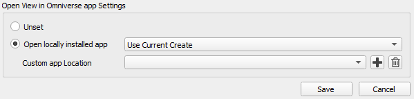
Open View in Omniverse App Settings
This part of the settings menu pertains to the application that is opened when clicking the Open View In Omniverse App button while an Omniverse Connector render view is active. It can be changed at any time, even when an Omniverse Connector render view has already been created.
Select either a specific version of the Omniverse app or use the most current installed version as your default viewer.
Press ‘Save’ to save the changes.
Element |
Result |
|---|---|
Unset |
Disable all Open View In Omniverse App settings.
|
Open locally installed app |
Omniverse app launch version, including options ‘Use Current’ and ‘Use Custom’ explained below.
|
Use Current/Use Custom |
‘Use Current’ locates current Omniverse USD Presenter or Omniverse USD Composer installs automatically, ‘Use Custom’ uses the ‘Custom app location’ value.
|
Custom View Location |
Allows selections of Omniverse app installs not found by the selection menu from ‘Open locally installed app’.
|
Save |
Commits the changes and closes the window.
|
Cancel |
Closes the window discarding all changes.
|
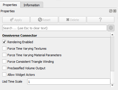
Omniverse Connector View Properties
The Omniverse Connector view properties are options pertaining to the currently active Omniverse Connector render view which can be changed at any time. They can apply to USD output just as well as anything else, such as disabling rendering output of an Omniverse Connector render view.
Element |
Result |
|---|---|
Rendering Enabled |
Set whether to render the output of the ParaView pipeline in the Omniverse Connector render view - improves efficiency when disabled. Has no bearing on USD output.
|
Force Time Varying Textures |
All actors will generate one texture or colormap per timestep if this option is enabled, instead of just a single texture or colormap for all timesteps.
|
Force Time Varying Material Parameters |
All actors will generate a separate material parameter value per timestep for each parameter that supports it if this option is enabled, instead of just a single parameter value for all timesteps.
|
Force Consistent Triangle Winding |
When set, any mesh triangle order that is inconsistent will be corrected, and normals regenerated.
|
Preclassified Volume Output |
For volumes, produce preclassified output where the transfer function is applied to the source data, producing a ‘density’ and ‘diffuse’ openvdb grid.
|
Allow Widget Actors |
Allow ParaView 3D viewport widgets (such as clip plane bounds and normal) to be output to USD.
|
Usd Time Scale |
Set the time scale which will be applied to the scene and all its actors in USD on output. Previously written timesteps remain in the scene with the old scale.
|