User Interface
Welcome Screen
The first thing you see is the Welcome To Omniverse Screen.
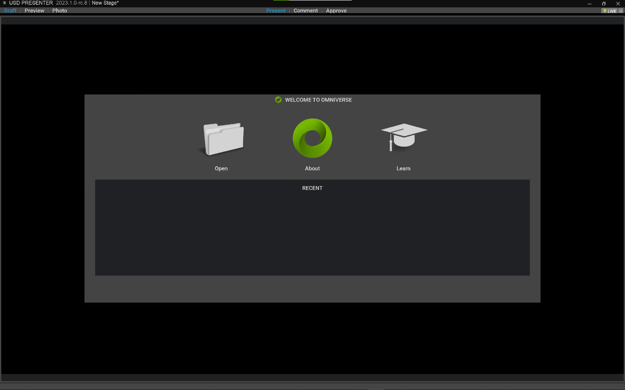
This screen allows you to:
“Open” an existing USD file
See the “About” Info for the program
“Learn” about USD Presenter
See “Recent” opened files with icon previews
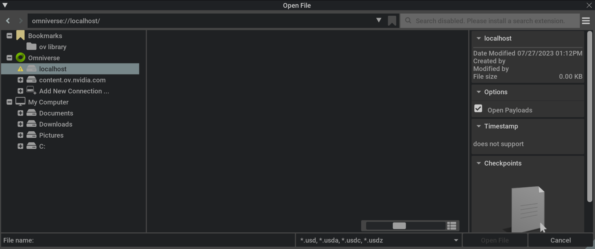
Open
Clicking the Open icon brings you to your file browser. From here you can select a local hard drive file, a local Nucleus file, or a remote Nucleus file on a server.
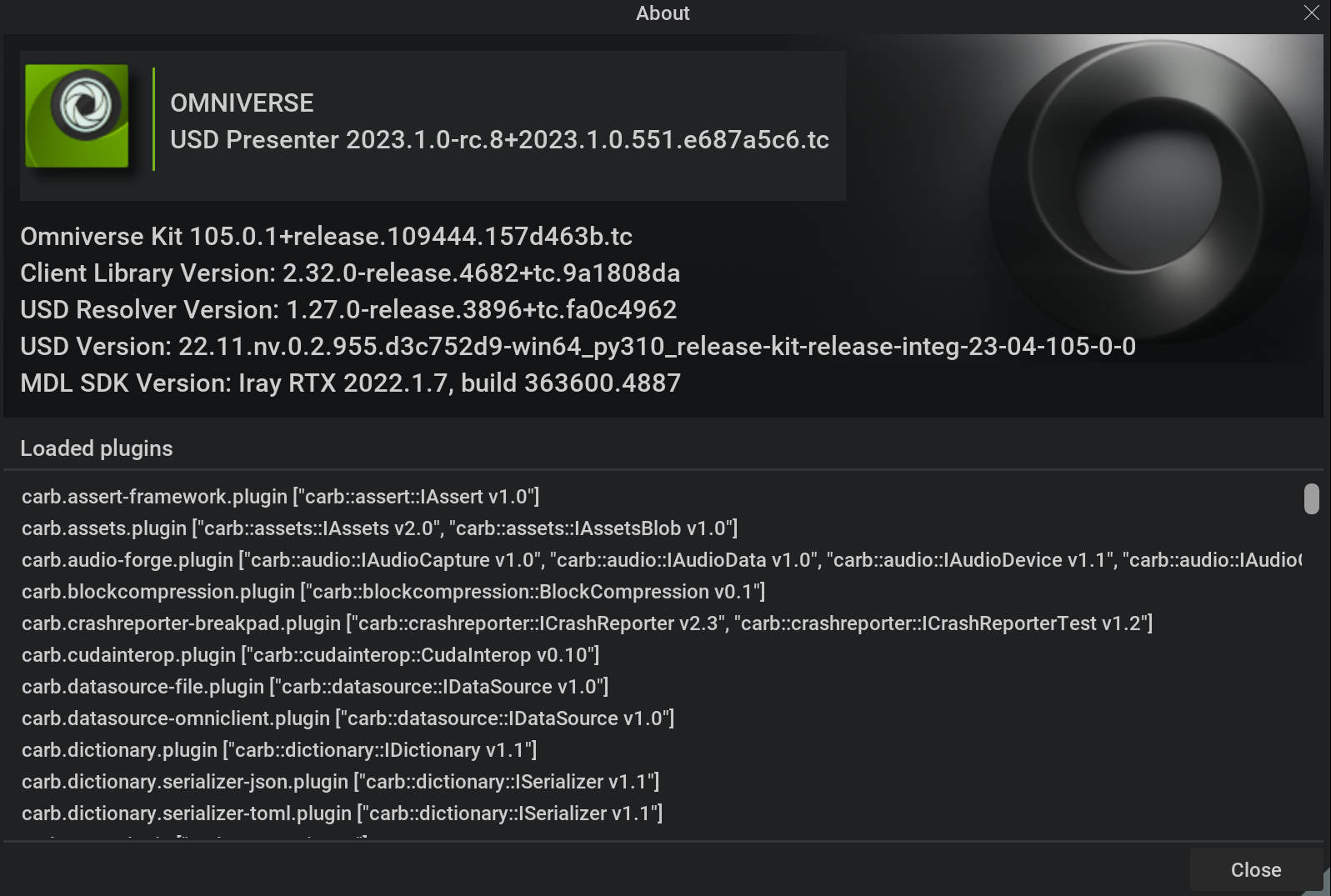
About
Here you can check your version number and see your loaded plugins
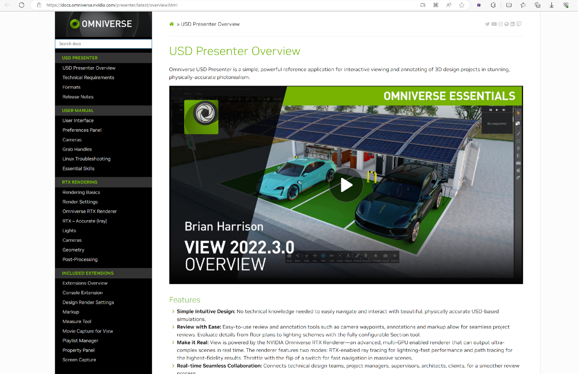
Learn
Clicking the Learn button takes your directly to our Omniverse Documentation portal, and shortcuts you directly to the USD Presenter page.
Viewing Your scene
USD Presenter offers 3 modes of Rendering Quality: Draft, Preview and Photo. There are also 3 modes of USD Review: Present, Comment and Approve. Explore the modes below.
The 3 different rendering modes can be mixed with the 3 different modes of review as desired.
Rendering Modes
In Draft Mode, the default rendering mode for USD Presenter, the usd file is displayed in our RTX Real-time renderer. This is a very powerful, real-time exploration mode, capable of displaying heavy, complex scenes with a smooth, highly responsive speed. It offers noise free, beautiful presentations of your scene, with rich textures, realtime reflections, and compelling lighting. This mode is intended for speed over quality, and makes it possible to review large amounts of data without fear of performance.

In Preview Mode, your scene will be rendered with our RTX Interactive (Path Tracing) renderer. This now renders your scene with highly accurate reflections, refractions and caustics to create a much more realistic look. Lighting is correctly calculated with path tracing, and multiple bounces of light will illuminate your complete scene. Whilst this mode is no longer “real-time” and performance will be slower than Draft mode, you will see a much higher quality representation of your work. You will see the scene “settle” as it renders samples. The longer it renders, the higher quality the image. Textures and details will become sharp.
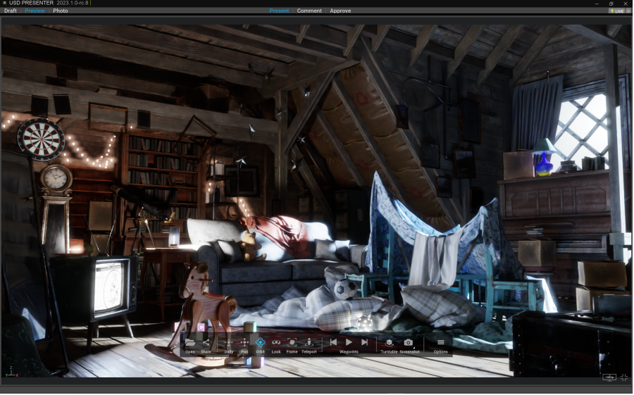
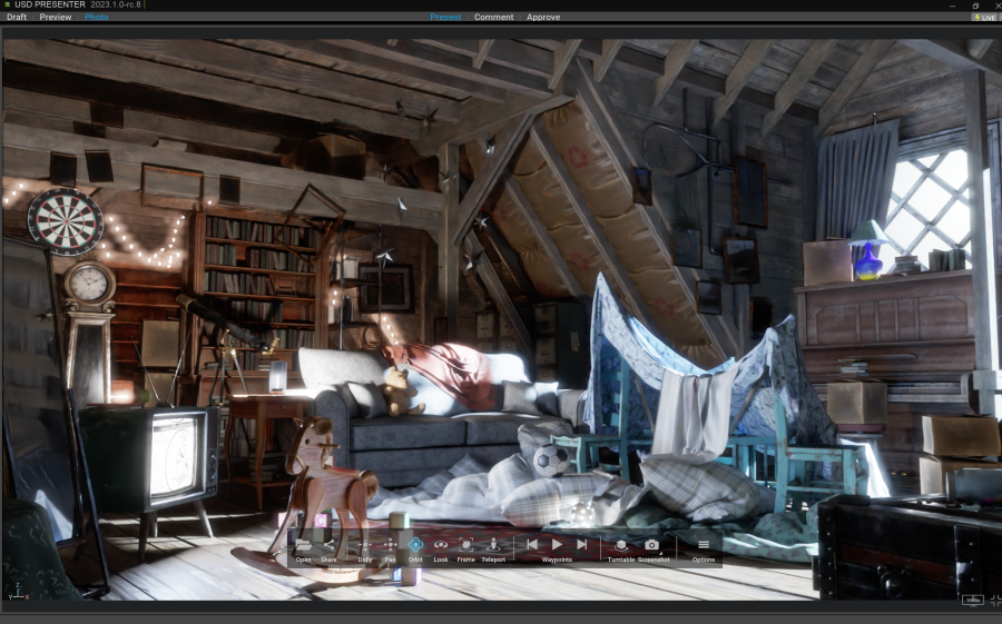
Photo Mode is our most accurate rendering mode, for truly photo real rendering. It is no surprise that this uses our Accurate (Iray) renderer. This mode is for uncompromised quality over interactive speed. Here the usd file will be extremely well presented for super accurate reflections, refractions, caustics, texture quality, lighting and effects. It also supports the highest fidelity in materials. This is good for final review at maximum quality. Like Preview mode, viewing in this mode will take time to resolve to full quality and will not be as responsive as Draft or Preview mode.
Review Modes
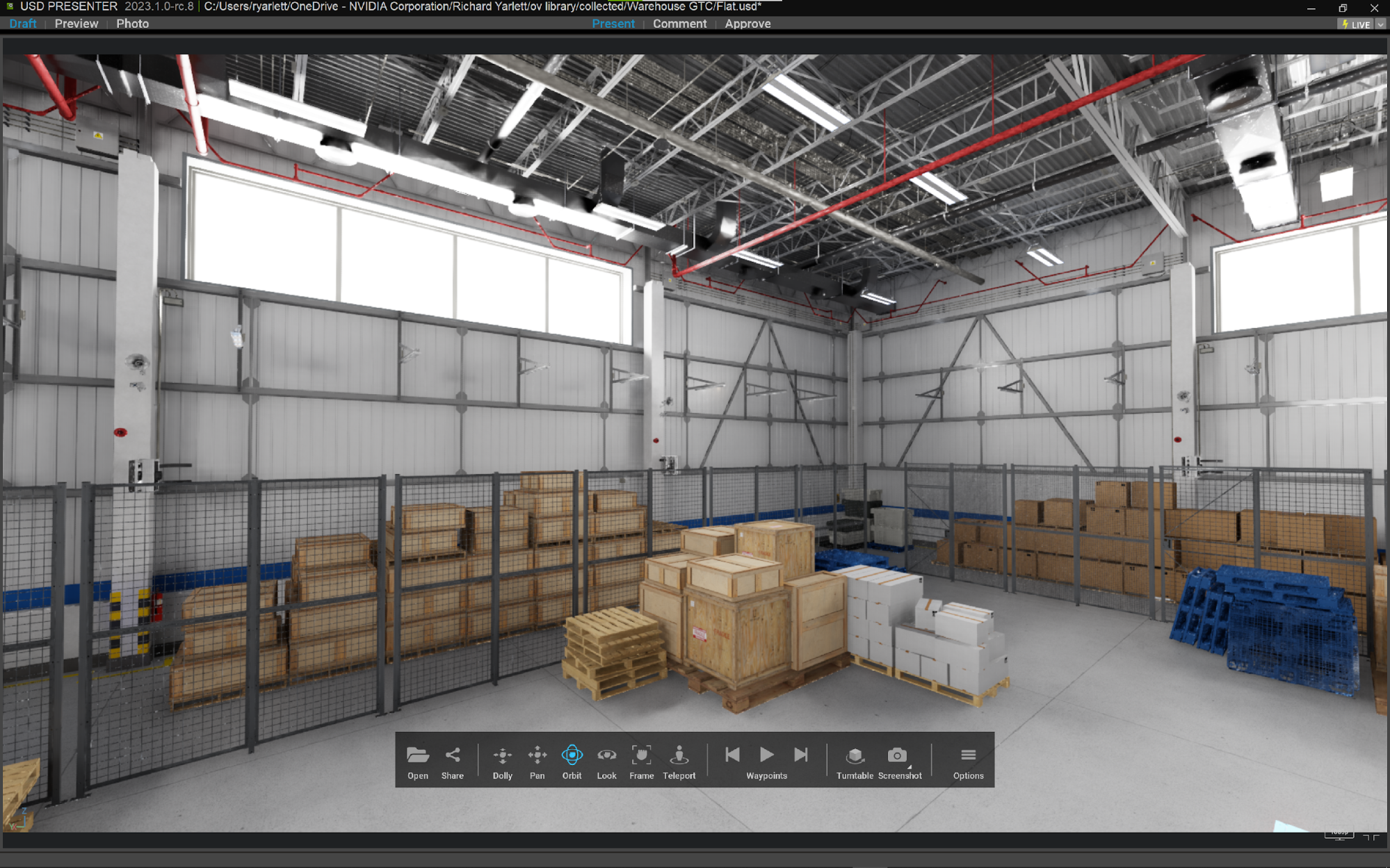
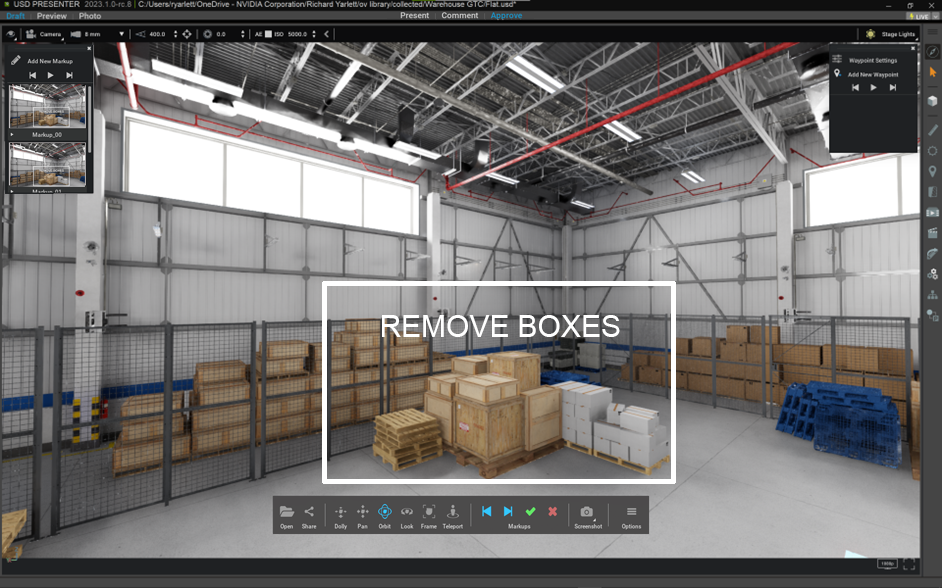
Present Mode is the default Review Mode for USD Presenter. In this mode, the user interface is very clean and simple. Options and tools are hidden away to allow for a near full screen review of your file. The only main element is the floating Main Toolbar in the lower middle portion of the screen (see Main Toolbar section below)
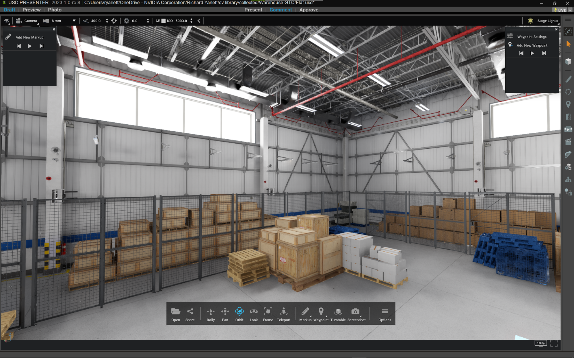
In Comment Mode, the user interface expands to offer new tools and options. Starting at the top, you have a visibility menu to control the viewport overlay options. On the top you have the Camera Toolbar (see Camera Toolbar). On the right, you have the Right Toolbar (see Right Toolbar). There are two new floating elements for adding Markups and Waypoints (see Markup Tool and Waypoint Tool)
In Approval Mode, the list of Markups is available for approval or rejection. The floating toolbar changes slightly to now offer two new buttons. Accept and Reject. A green arrow, or a red “X”.
Floating Toolbar
The floating toolbar is a movable user interface element with a lot of useful navigation features and tools.


Note: Markup and Waypoint added.

Note: Markup Accept and Reject added.
Menu Item |
Description |
|---|---|
Open |
To open the USD file browser. |
Share |
To share your scene file with an omniverse nucleus link |
Dolly, Pan, Orbit, look |
Various navigation tools to move around your scene with ease. The default mode is “Orbit” for smooth rotation of your point of view. |
Frame |
Frame will zoom into and “frame” your point of view on a selected object. If nothing is selected it will frame the whole scene. |
Teleport |
This tool will allow for quick navigation around the scene by selecting a point in your viewport to “teleport” to with a single jump. Place the icon where you would like to jump to, without traveling. |
Waypoints |
In Present mode: these three buttons control the playback of your waypoints. Play, Previous and Next. In Comment mode: the button changes to the Waypoint button to toggle the waypoint panel on and off. |
Markup |
In Present mode: Not available. In Present mode: The Markup button toggles the markup panel on and off. |
Turntable |
Select an object in the viewport to use this mode. It will show a new rotation slider to rotate the selected object around the z-axis, either clockwise or counter-clockwise. You can also set playback speed. Exit this mode to return the object to normal. 
|
Screenshot |
Use this button to take a screenshot of the current viewport. You can set screenshot options in the Preferences panel. |
Options |
This takes you to the Preferences Panel. |
Focus Mode
These two icons allow you to enter and exit “Focus Mode”:
Icon |
Description |
|---|---|
When in Focus Mode: the right toolbar and the camera toolbar are hidden, to reveal a minimal user interface. |
|
When out of Focus Mode: The right toolbar and the camera toolbar are visible, offering more tools and options. |
Viewport Resolution menu
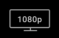
You can change the viewport resolution at any time, by selecting this button in the lower right hand corner of the screen. This will bring up the (4) preset resolutions and any custom resolution options you have added (see preferences)
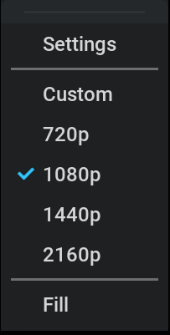
The default startup resolution is 1080p (1920x1080/HD).
The FILL option is an additional special option that runs the viewport at direct resolution (1:1) pixels
Note
This option can be very demanding on your GPU for high resolution displays
Camera Toolbar

The camera toolbar is divided into (3) sections:
Visibility options
Camera options
Exposure options
Visibility Options

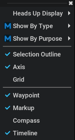
The visibility menu controls what overlays are visible in the viewport:
Heads Up Display (submenu)
Show By Type (submenu)
Show By Purpose (submenu)
Selection Outline (on/off)
Axis (on/off)
Grid (on/off)
Waypoint (on/off)
Markups (on/off)
Compass (on/off)
Timeline (on/off)
Camera Options

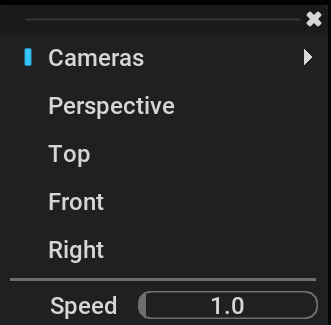
Camera Select
Lens Select
Focal Distance
Focal Target
Camera F-Stop
Exposure Options
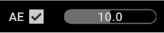
Automatic Exposure (AE) on / off.
Slider to set the exposure value.
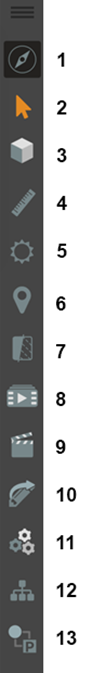
Right Toolbar
# |
Icon |
Description |
|---|---|---|
1 |
Orbit Mode |
Toggle Orbit Mode on and off. |
2 |
Select |
Use the Select Arrow for selecting geometry (Orbit Mode must be disabled). |
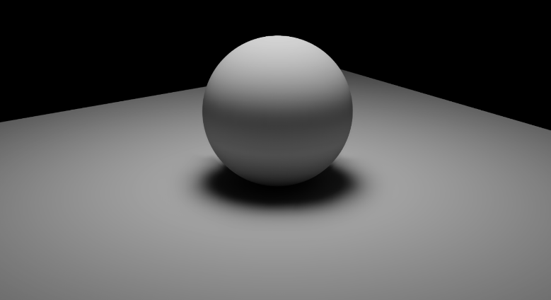
3 |
White Mode |
Toggles White Mode on and off. White Mode overrides all the materials in the scene. |
4 |
Measure Tool |
Opens the Measure Tool Panel |
5 |
Sun Study Tool |
Opens the Sun Study Panel (Requires the usd file to contain a dynamic sky) |
6 |
Sun Study Location |
Opens the Sun Study Location Panel (Requires the usd file to contain a dynamic sky) |
7 |
Section Tool |
Opens the Section Tool Panel |
8 |
Playlist |
Opens the Playlist Panel |
9 |
Movie Capture |
Opens the Movie Capture Panel |
10 |
Markup Export |
Opens the Markup Export Panel |
11 |
Render Settings |
Opens the Rendering Settings Panel |
12 |
Stage |
Opens the Stage Panel |
13 |
Variants |
Opens the Variants Panel |
1. Orbit Mode
This is the default way Presenter allows you to navigate your scene. There are other movement options available on the Floating Toolbar but orbit in the primary method.
2. SELECT
Use this arrow to select geometry in the scene.
3. WHITE MODE
This mode overrides all the materials in the scene with a default “DebugWhite” material. This is very useful for viewing a scene with the distraction of color and texture. Just lighting
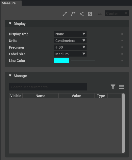
4. MEASURE TOOL
The Measure Tool helps you truly understand the scale and makeup of your design in a physical sense. This tool lets you pick two meshes and measure between them or make measurements across any number of meshes using the various sub-tools Point-to-Point, Multi-Point, Angle, and Area.
Control over the dimension is available through a min/max/center toggle which adjusts the type of measurement. Min is the minimum distance between two objects. Max is the maximum distance between two objects. And finally, Center is the distance between the centers of each mesh. Note that you can control the direction of the measure against the X, Y or Z axes as desired.
Other options allow you to set the unit of measure, color of the dimension, precision shown in the dimension’s text as well as a general height of the text.
Dimensions can be selected and deleted.
Option |
Description |
|---|---|
Measure Selected Mode Row |
Mix, max center toggle adjusts the type of measurement. |
Measure Selected |
Measures the distance between two prims using the Measure Selected Mode type. |
Area |
Measures an area between the selected points. |
Angle |
Measure the acute and obtuse angles in a corner. |
Multi-point |
Measures distance between multiple points. |
Point-to-point |
Measures distance between two points |
Snap To |
Vertex: Objects snap to the vertices of another object Midpoint Center Edge: Objects snap to the edges of another object. Pivot |
Constrain To |
StageUp (X, Y, Z) |
Display XYZ |
Visualize Axis Dimensions in both Local and World coordinates. Default is None |
Units |
Controls display of measurements in common units (centimeter, inch, millimeter, etc.). |
Precision |
Determines how many decimal places to use before rounding. |
Label Size |
Determines the size and legibility of the display. |
Line Color |
Defines the color of the Measurement Indicators. |
General Use
Activate Measure Tool by clicking on the Measure icon in the right-hand menu bar.
Select the type of measurement desired - point-to-point, multi-point, angle and area.
Adjust the options as required for your measuring operation in the Measure panel.
Select a primitives in the scene, by left clicking on it.
Move over to the next primitive in the scene. Left click to lock it.
A measurement is then established denoting distance in the viewport.
Deleting a Measurement
Can be done in a number of ways.
To delete the measurement, click on the measurement in the viewport.
Clicking on the Measure Icon again deletes the measurement.
Deactivating the measure tool
Right-click to Deactivate the measure tool during multi-point measurement
5. Sun Study Tool
This Omniverse Extension allows users to review models with accurate sunlight. You need to set Dynamic Sky to your scene using Omniverse Create prior to using the sun study tool in Omniverse USD Presenter.
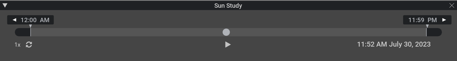
The Sun Study interface allows you to play through a day and night 24 hr cycle and watch the change in lighting dynamically. You can set minimum and maximum markers to shorten the length of the cycle to your desired times. You can scrub the timeline and select a specific time of day.
Note
Many tools give GPS coordinate data. This is not the same as latitude and longitude. GPS coordinates include a North/South by East/West designation. To convert to latitude and longitude, invert West or South designations with a negative value. For example convert 22 degrees South (22.00’000 South) to –22.00.000 and 35 degrees West (35.00’000 West) to –35.00.000. Ignore East and North designations, because they’re both positive and do not require any alterations to work.
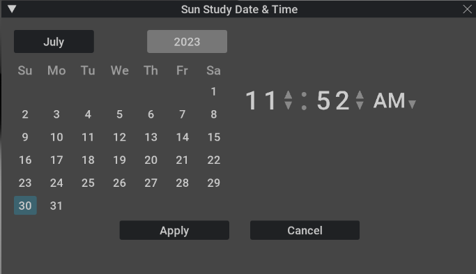
DATE AND TIME
You can set the date and time for the Sun Study for accurate lighting results. To access the Sun Study Date & Time panel, click the date and time indicator in the Sun Study panel:
Option |
Description |
|---|---|
Month Select |
Sets Sun position for the month selected. |
Year Select |
Sets Sun position for the year selected. |
Calendar Day Select |
Sets Sun position for the day selected. |
Time Selected |
Sets Sun position for the time selected. |
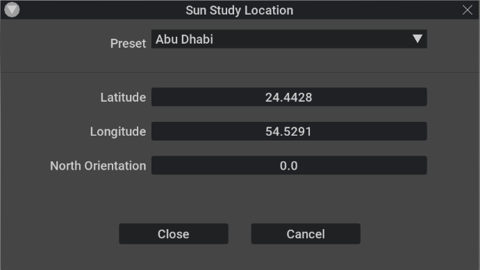
6. Sun Study Location
Option |
Description |
|---|---|
Preset |
Shows a list of predefined geographical locations. |
Latitude |
Sets the latitudinal position in degrees, minutes, seconds. |
Longitude |
Sets the longitudinal position in degrees, minutes, seconds. |
North Orientation |
Sets the North offset rotation. |
7. Section Tool
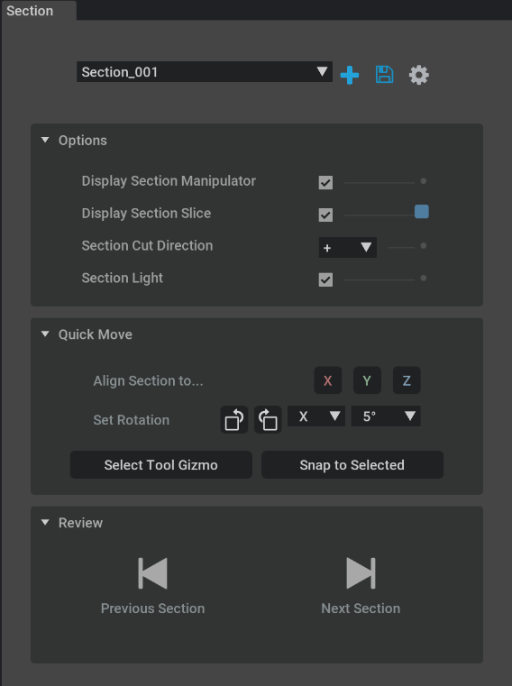
Option |
Description |
|---|---|
Display Section Manipulator |
Shows the manipulator icon. |
Display Section Slice |
Shows the slicing plane through the geometry. |
Section Cut Direction |
Option to pick the direction of the cut. |
Section Light |
Option to include the lights with the section cut. |
Align Section to |
Aligns the section cut to either x, y, or z. |
Set Rotation |
Sets the rotation of the section cut. |
Select Tool Gizmo |
|
Snap to Selected |
Snaps the section cut to the selected geometry. |
Review |
Plays through the sections cuts in order. |
8. Playlist
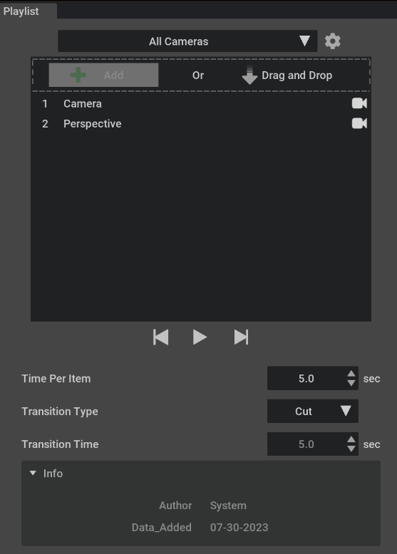
Opens the Playlist Panel which allows you to set a list of cameras to play through in order. You can set the time per camera, the transition type and the transition time. Click the Add button to add more cameras. Drag and drop to re-order the playlist.
9. Movie Capture
Opens the Movie Capture Panel, which allows you to capture your stills and animations to your hard drive. You can select your rendering method, resolution and render location. This is a shared extension with Composer.
10. Markup Export
Opens the Markup Export Panel, which allows you to export your markups to a PDF document.
11. Render Settings
Opens the Rendering Settings Panel to allow you to set the viewport options exactly the way you prefer to view your scene. From here you can select the RTX Real-Time, Interactive (Path Tracing), or Accurate (Iray) renderers. This is a shared extension with Composer.
12. Stage
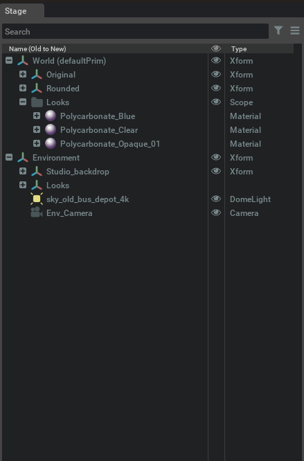
Opens the Stage Panel, which allows you to see your USD file structure in a hierarchy format. You can search for specific assets by name. You can re-order the list in a variety of ways, such as “A to Z” or “Old to New”. You can filter for specific types of assets, such as Lights and Cameras.
13. Variants
Opens the Variants Panel, which allows you to view all of the variants stored in the USD file.
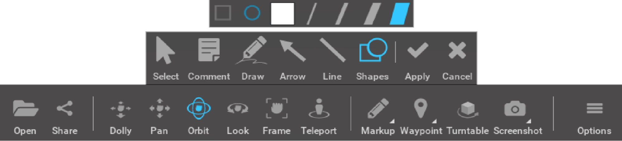
Markup Tool
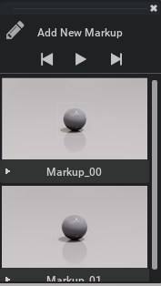
The Markup Extension is a tool to add ideas and comments to a model. With this tool, you can add text (comment), free hand scribbles, arrows/lines, boxes and circles. In time, this set of tools will be expanded. Each markup that is created is fixed to a view orientation in the model so that you can go back and see them where they were created. It’s a 2D layer on top of the 3D model. Each markup can be edited to update comments or delete them, as needed.
Note
Markups can only be created in Comment Mode.
Create Markups
Left click the Markup/Pencil icon to create a markup.
Delete Markups
Left click the trashcan icon to delete a markup.
Markup Interface
Option |
Description |
|---|---|
Select |
Select image, or background for markup. |
Comment |
Open a comment box for adding text |
Draw |
Draw lines or squiggles in different colors and thickness. |
Arrow |
Draw single or double sided arrow in different colors and thickness. |
Line |
Draw lines in different colors and thickness. |
Shapes |
Draw circles or squares in different colors and thickness. |
Review Markups
Right-Click on Markup icon to reveal existing markups created for the scene.
Left-Click on any Markup to open that markup in the Viewport.
Export Markups
You can export markups to common formats for further use beyond Omniverse:
Left-Click on Markup Export icon on the right hand side toolbar.
Make your selections in the popup window.
Waypoints Tool
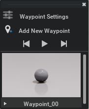
The Waypoints Tool allows you to create saved viewpoints with names, that can be easily recalled as a list. By moving around the scene and creating a waypoint marker, that exact view can be recalled by simply clicking on that waypoint marker in the viewport, or from the Waypoint Panel. Waypoints can be named, renamed, updated and deleted. It is both a point in space and a specific camera view
Note
Waypoints can only be created in Comment Mode.
Create Waypoints
Left-click the Waypoint/Marker icon to create a waypoint.
Delete Waypoints
Left-click the trashcan icon to delete a waypoint.
Screen Capture Tool
The screen capture tool is an Omniverse Extension that allows users to take a variety of “screenshots” of their current window quickly and easily.
Capture a Screenshot
Left Click on Capture Icon to take a screenshot using current settings.
Additional Options
To reveal the additional screenshot functions, Right Click bottom right corner of icon (triangle) to reveal drop down list.
Option |
Description |
|---|---|
Screenshot |
Captures the screen at current resolution. |
SuperRes |
Increased resolution screen shot for Higher Quality images. |
360 Capture |
Captures 360 degree. |
Screenshot Settings |
Open the Preference Panel for Screenshots. |
USD Presenter Screenshots |
Quickly locate screenshots. Opens the folder where the screenshots are saved. |