6.6. Configuring RMPflow for a New Manipulator
6.6.1. Learning Objectives
In this tutorial, we will see how the RMPflow algorithm may be fully configured following the creation of a Robot Description File.
6.6.2. Getting Started
Prerequisites
Please complete the Lula Robot Description Editor tutorial to create one of the two required configuration files for using RmpFlow.
Please review the Adding a New Manipulator tutorial prior to beginning this tutorial to obtain a robot Articulation USD asset.
This tutorial provides a URDF file and USD file describing the Cobotta Pro 900 robot. The USD file was generated from the URDF using the process discussed in Adding a New Manipulator tutorial.
The reader may download the following Zip file to follow along with the tutorial:
6.6.3. Using the Lula Test Widget
This tutorial demonstrates how RMPflow can be configured and tested on a new robot using the Lula Test Widget. The Lula Test Widget is an extension that can be enabled in the Extensions menu as shown below, and then accessed under “Isaac Utils -> Lula Test Widget”.
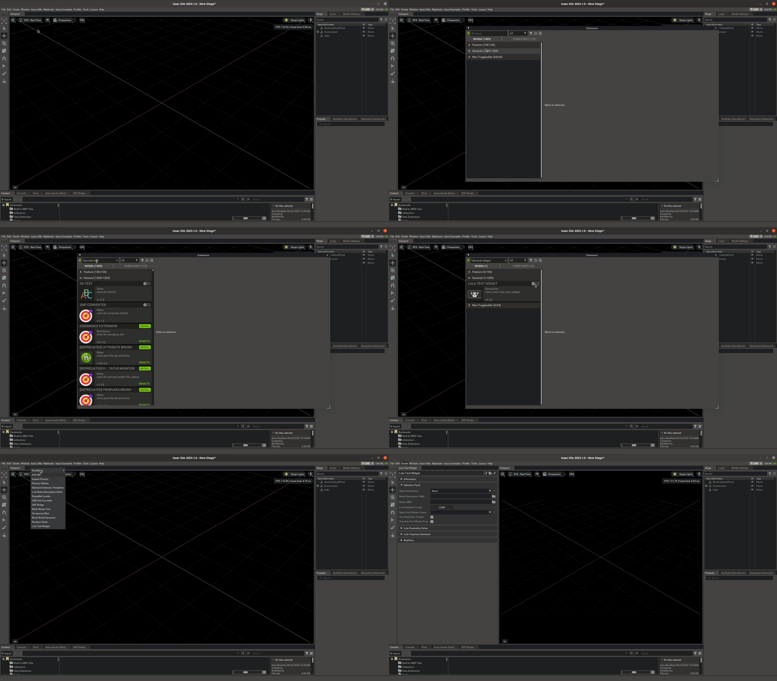
This extension allows the user to select their RMPflow config files along with a selected robot Articulation on the USD stage and run simple scenarios to verify that RMPflow is working as intended. Once each type of required config file is created, they can be loaded and used in the Lula Test Widget.
6.6.4. Template RmpFlow Config File
There are three files to describe the robot and parameterize the RMPflow algorithm:
A URDF (universal robot description file), used for specifying robot kinematics as well as joint and link names. Position limits for each joint are also required. Other properties in the URDF are ignored and may be omitted; these include masses, moments of inertia, visual and collision meshes, etc.
A supplementary robot description file in YAML format. This file can be generated using the Lula Robot Description Editor UI tool.
A RMPflow configuration file in YAML format, containing parameters for all enabled RMPs.
This tutorial assumes that the user is starting with a URDF file describing their robot and has created a Robot Description File using the Lula Robot Description Editor. In this tutorial, a template files is provided for the remaining RMPflow configuration, which is modified in order to match the Cobotta Pro 900 robot. The provided tutorial zip file contains a completed robot_description.yaml for the Cobotta Pro 900.
6.6.4.1. Template RmpFlow Config YAML File
The RMPflow algorithm has over 50 settable parameters, but these parameters tend to generalize between robots with similar kinematic structures and length scales. The values in the template have been tuned specifically for the Franka Emika Panda, but serve as a good starting point for many 6- and 7-dof robot arms. The template file can be found in the provided tutorial zip at ./rmpflow_configs/template_rmpflow_config.yaml.
 1# Artificially limit the robot joints.  For example:
 2# A joint with range +-pi would be limited to +-(pi-.01)
 3joint_limit_buffers: [.01, .01, .01, .01, .01, .01, .01]
 4
 5# RMPflow has many modifiable parameters, but these serve as a great start.
 6# Most parameters will not need to be modified
 7rmp_params:
 8    cspace_target_rmp:
 9        metric_scalar: 50.
10        position_gain: 100.
11        damping_gain: 50.
12        robust_position_term_thresh: .5
13        inertia: 1.
14    cspace_trajectory_rmp:
15        p_gain: 100.
16        d_gain: 10.
17        ff_gain: .25
18        weight: 50.
19    cspace_affine_rmp:
20        final_handover_time_std_dev: .25
21        weight: 2000.
22    joint_limit_rmp:
23        metric_scalar: 1000.
24        metric_length_scale: .01
25        metric_exploder_eps: 1e-3
26        metric_velocity_gate_length_scale: .01
27        accel_damper_gain: 200.
28        accel_potential_gain: 1.
29        accel_potential_exploder_length_scale: .1
30        accel_potential_exploder_eps: 1e-2
31    joint_velocity_cap_rmp:
32        max_velocity: 4.
33        velocity_damping_region: 1.5
34        damping_gain: 1000.0
35        metric_weight: 100.
36    target_rmp:
37        accel_p_gain: 30.
38        accel_d_gain: 85.
39        accel_norm_eps: .075
40        metric_alpha_length_scale: .05
41        min_metric_alpha: .01
42        max_metric_scalar: 10000
43        min_metric_scalar: 2500
44        proximity_metric_boost_scalar: 20.
45        proximity_metric_boost_length_scale: .02
46        xi_estimator_gate_std_dev: 20000.
47        accept_user_weights: false
48    axis_target_rmp:
49        accel_p_gain: 210.
50        accel_d_gain: 60.
51        metric_scalar: 10
52        proximity_metric_boost_scalar: 3000.
53        proximity_metric_boost_length_scale: .08
54        xi_estimator_gate_std_dev: 20000.
55        accept_user_weights: false
56    collision_rmp:
57        damping_gain: 50.
58        damping_std_dev: .04
59        damping_robustness_eps: 1e-2
60        damping_velocity_gate_length_scale: .01
61        repulsion_gain: 800.
62        repulsion_std_dev: .01
63        metric_modulation_radius: .5
64        metric_scalar: 10000.
65        metric_exploder_std_dev: .02
66        metric_exploder_eps: .001
67    damping_rmp:
68        accel_d_gain: 30.
69        metric_scalar: 50.
70        inertia: 100.
71
72canonical_resolve:
73    max_acceleration_norm: 50.
74    projection_tolerance: .01
75    verbose: false
76
77
78# body_cylinders are used to promote self-collision avoidance between the robot and its base
79# The example below defines the robot base to be a capsule defined by the absolute coordinates pt1 and pt2.
80# The semantic name provided for each body_cylinder does not need to be present in the robot URDF.
81body_cylinders:
82     - name: base
83       pt1: [0,0,.333]
84       pt2: [0,0,0.]
85       radius: .05
86
87
88# body_collision_controllers defines spheres located at specified frames in the robot URDF
89# These spheres will not be allowed to collide with the capsules enumerated under body_cylinders
90# By design, most frames in industrial robots are kinematically unable to collide with the robot base.
91# It is often only necessary to define body_collision_controllers near the end effector
92body_collision_controllers:
93     - name: end_effector
94       radius: .05
This tutorial focuses on three fields in this file: joint_limit_buffers, body_cylinders, and body_collision_controllers.
joint_limit_buffers introduces artificial joint limits around the joint limits stated in the robot URDF. The shape of the provided joint_limit_buffers must match the c-space given in the robot_description.yaml file. Imagining that our template robot has seven revolute joints, The given buffers of .01 on the 7 c-space joints mean that RMPflow will drive the robot up to .01 radians from the joint limits given in the robot URDF. If the robot has prismatic joints, a value of .01 would be expressed implicitly in meters.
body_cylinders and body_collision_controllers help RMPflow to avoid self-collision between the end effector and the robot base. body_cylinders define an imagined robot base via a set of capsules. body_collision_controllers define collision spheres placed on different frames of the robot URDF. The template code above defines an unmoving capsule in absolute coordinates and a sphere centered around the “end_effector” frame in the robot URDF. RMPflow will not allow a collision between the sphere and capsule. Apart from preventing the end effector from colliding with the base, RMPflow does not directly avoid self-collisions based on collision geometry. For most applications, however, joint limits are sufficient to prevent links in the middle of the kinematic chain from colliding with each other.
6.6.5. Modifying our Template for the Cobotta Pro 900
6.6.5.1. Doing the Bare Minimum
First we show the minimum changes required to get our Cobotta to be able to use RMPflow to follow a target.
The rmpflow_config file requires little work to get started (./rmpflow_configs/rmpflow_config_basic.yaml in the provided tutorial zip):
 1# Artificially limit the robot joints.  For example:
 2# A joint with range +-pi would be limited to +-(pi-.01)
 3joint_limit_buffers: [.01, .01, .01, .01, .01, .01]
 4
 5#Omitting `rmp_params` argument
 6
 7# body_cylinders are used to promote self-collision avoidance between the robot and its base
 8# The example below defines the robot base to be a capsule defined by the absolute coordinates pt1 and pt2.
 9# The semantic name provided for each body_cylinder does not need to be present in the robot URDF.
10body_cylinders:
11     - name: base
12       pt1: [0,0,.333]
13       pt2: [0,0,0.]
14       radius: .05
15
16
17# body_collision_controllers defines spheres located at specified frames in the robot URDF
18# These spheres will not be allowed to collide with the capsules enumerated under body_cylinders
19# By design, most frames in industrial robots are kinematically unable to collide with the robot base.
20# It is often only necessary to define body_collision_controllers near the end effector
21body_collision_controllers:
22     - name: right_inner_finger
23       radius: .05
To get our robot moving around, we can ignore the rmp_params argument for now. We modify the joint_limit_buffers argument to represent that our robot only has 6 DOFs rather than the 7 listed in the template. We have to provide body_cylinders, but for now we won’t worry about doing a good job representing the robot base. One change was required to the default body_collision_controllers argument, which is to change the frame at which we place a collision sphere. There is no “end_effector” frame in the Cobotta URDF, so for now we pick a frame that is near the end effector: right_inner_finger.
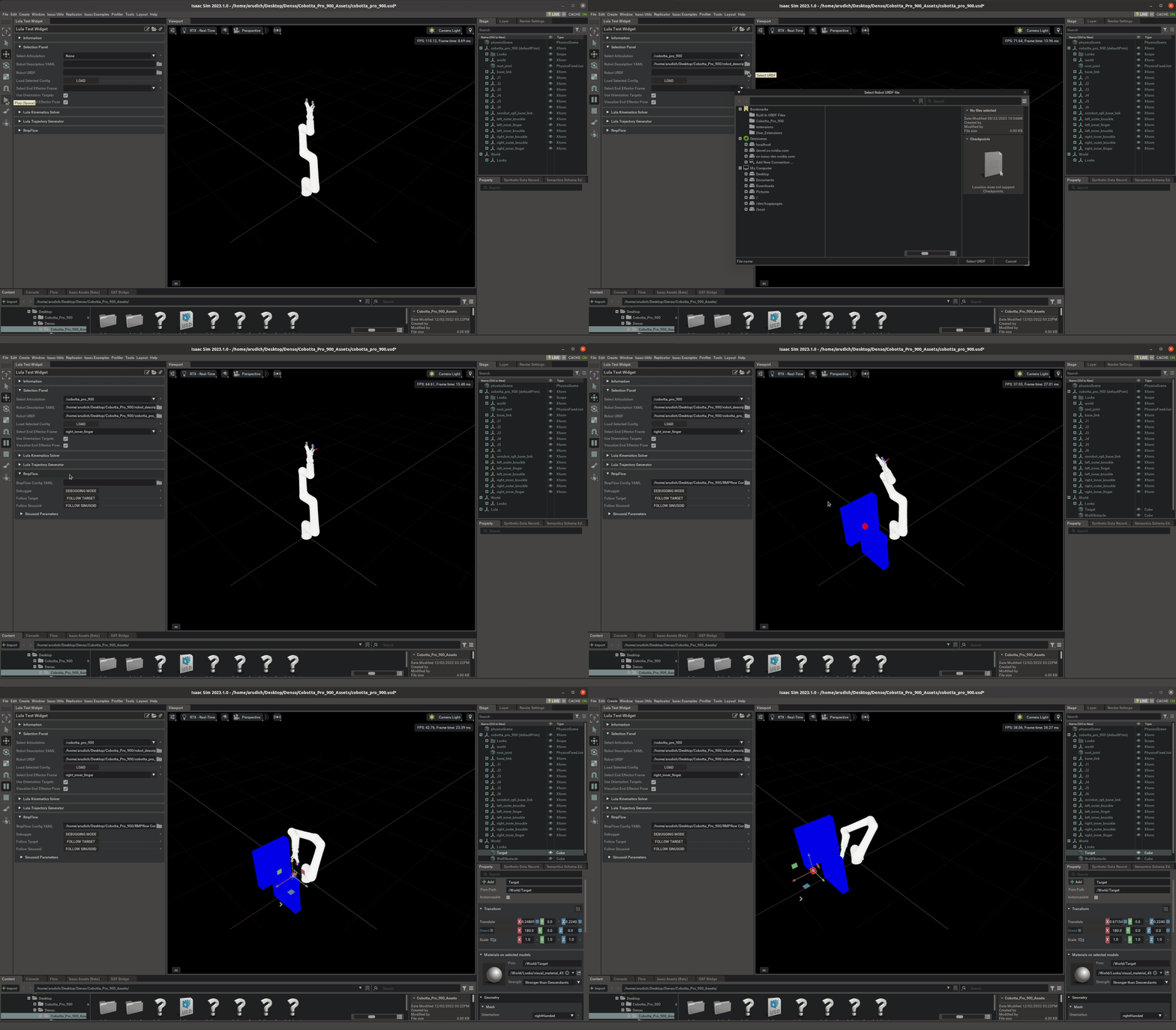
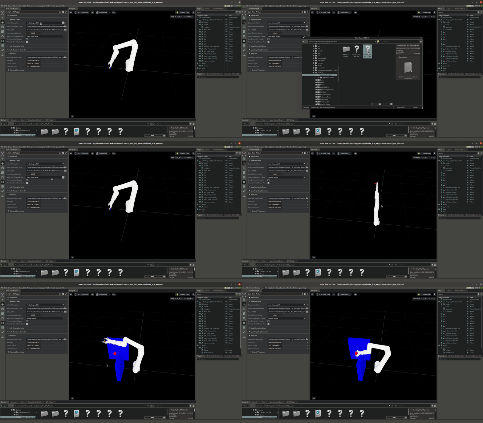
In the Lula Test Widget, we see that our robot is able to follow the target and avoid obstacles pretty well! The reader will notice that the frame that RMPflow is moving to the target position is not in the center of the gripper. In the Lula Test Widget, the right_inner_finger is selected as the end effector frame. The available end effector frames come from the robot URDF file, and there is not a frame resting in the center of the gripper. Creating such a frame will be covered later in this tutorial.
This video selects three of the provided config files:
./robot_description.yaml
./cobotta_pro_900.urdf
./rmpflow_configs/cobotta_rmpflow_config_basic.yaml
6.6.5.2. Avoiding Self-Collision: Configuring Body Cylinders and Body Collision Controllers
With a completed Robot Description File taken care of, our robot will avoid collisions with external obstacles, but it will not avoid self-collision. Currently, there is limitted tooling available for avoiding self-collision because industrial robot arms typically remove most potential for self-collision with joint limits. However, some exploration is required with a particular robot to see what types of self-collision are possible. With the preliminary configuration of body cylinders and body collision controllers we set in our cobotta_rmpflow_config_basic.yaml file, it is easy to cause collisions between the robot end effector and the robot base:
This video selects the same three of the provided config files:
./robot_description.yaml
./cobotta_pro_900.urdf
./rmpflow_configs/cobotta_rmpflow_config_basic.yaml
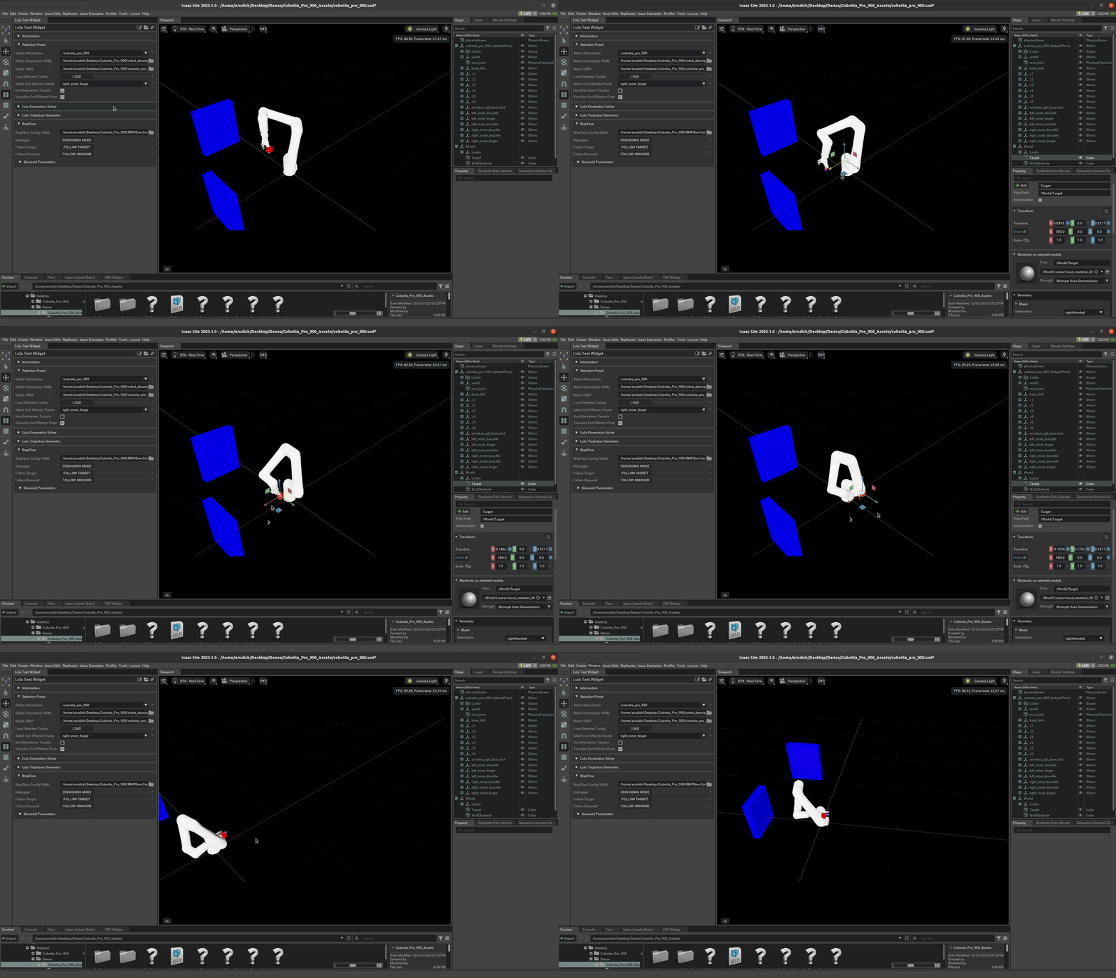
body_cylinders define an imagined robot base via a set of capsules. body_collision_controllers define collision spheres placed on different frames of the robot URDF. RMPflow will not allow these spheres and capsules to come into contact with each other. In our basic rmpflow config, we defined the base as the capsule connecting two spheres of radius .05 m at the absolute coordinates ([0,0,0], [0,0,.333]) (see Doing the Bare Minimum), and we define a single body_collision_controller at the right_inner_finger frame. In the video above, we can see that the gripper will not pass directly throught the robot base, but it is easy to facilitate a self-collision with the edge of the robot base, or the base of the second link. The self-collision tooling available in RMPflow does not allow us to avoid all self-collisions without sacrificing some acceptible robot configurations as well. To make self collisions completely impossible for the Cobotta, we would need a very conservative estimate of the robot base; essentially we would not allow the gripper to move close to the base at all. Choosing the best possible configuration is use-case dependent. There is no reason to take away maneuverability around the robot base unless we actually see that the robot is self-colliding.
One potential configuration is given in this tutorial that covers the other frames in the gripper and exaggerates the size of the robot base in order to make it harder for the gripper to intersect with the robot’s second link. The sizes and locations for the capsule and spheres are based on the collision spheres that we’ve already added.
 1# body_cylinders are used to promote self-collision avoidance between the robot and its base
 2# The example below defines the robot base to be a capsule defined by the absolute coordinates pt1 and pt2.
 3# The semantic name provided for each body_cylinder does not need to be present in the robot URDF.
 4body_cylinders:
 5     - name: base
 6       pt1: [0,0,.12]
 7       pt2: [0,0,0.]
 8       radius: .08
 9     - name: second_link
10       pt1: [0,0,.12]
11       pt2: [0,0,.12]
12       radius: .16
13
14
15# body_collision_controllers defines spheres located at specified frames in the robot URDF
16# These spheres will not be allowed to collide with the capsules enumerated under body_cylinders
17# By design, most frames in industrial robots are kinematically unable to collide with the robot base.
18# It is often only necessary to define body_collision_controllers near the end effector
19body_collision_controllers:
20     - name: J5
21       radius: .05
22     - name: J6
23       radius: .05
24     - name: right_inner_finger
25       radius: .02
26     - name: left_inner_finger
27       radius: .02
28     - name: right_inner_knuckle
29       radius: .02
30     - name: left_inner_knuckle
31       radius: .02
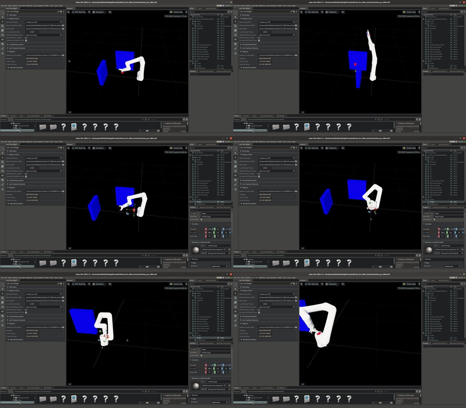
We represent the robot base link “J1” with a capsule of radius .08 m, which matches the size of the collision spheres in near the base of the robot. We represent the robot’s second link with a large sphere of radius .12. In the Lula Test Widget, we see that the robot does a much better job avoiding collisions with the first and second link. As expected, it is still possible to cause a self-collision, but the cases are much more limitted.
This video selects three of the provided config files:
./robot_description.yaml
./cobotta_pro_900.urdf
./rmpflow_configs/cobotta_rmpflow_config_final.yaml
6.6.5.3. Creating an End Effector Frame
A detail that the user will likely have noticed when following this tutorial is that our chosen end effector frame “right_inner_finger” does not directly represent the position of the robot’s gripper. The frame that RMPflow considers to be the end effector must be present in the robot URDF. In this tutorial, we selected a frame near the end of the robot as our best option. To directly control where the center of the gripper is, the user has two options:
The user may manually compute transforms between their desired target and the target they send to RMPflow at runtime.
The user may add a frame to the robot’s URDF.
This tutorial covers the second option by adding a frame to the Cobotta Pro 900 URDF. A common choice of end effector position is in the center of the gripper, with two principal axes aligned with the gripper fingers.
Investigating our Cobotta Pro 900 URDF, we can see how the “right_inner_finger” frame is connected to the robot arm. In the URDF, we see that the “right_inner_finger” joint is a grandchild of the “onrobot_rg6_base_link” frame (which is at the gripper base).
 1<joint name="right_inner_finger_joint" type="revolute">
 2    <origin rpy="0 0 0" xyz="0 -0.047334999999999995 0.064495"/>
 3    <parent link="right_outer_knuckle"/>
 4    <child link="right_inner_finger"/>
 5    <axis xyz="1 0 0"/>
 6    <limit effort="1000" lower="-0.872665" upper="0.872665" velocity="2.0"/>
 7    <mimic joint="finger_joint" multiplier="1" offset="0"/>
 8  </joint>
 9
10<joint name="right_outer_knuckle_joint" type="revolute">
11    <origin rpy="0 0 3.141592653589793" xyz="0 0.024112 0.136813"/>
12    <parent link="onrobot_rg6_base_link"/>
13    <child link="right_outer_knuckle"/>
14    <axis xyz="1 0 0"/>
15    <limit effort="1000" lower="-0.628319" upper="0.628319" velocity="2.0"/>
16    <mimic joint="finger_joint" multiplier="-1" offset="0"/>
17  </joint>
This tells us that we can create a frame that is offset from the “onrobot_rg6_base_link” frame by a pure Z offset of .064495+.136813=.2013 to represent a point in the center of the gripper, aligned with the “right_inner_finger_joint” and “left_inner_finger_joint”. To get closer with the tips of the fingers, we increase the Z offset to .24.
We add a link to our URDF called “gripper_center”, whose offset from the parent link “onrobot_rg6_base_link” is defined by the connection “gripper_center_joint”. In the provided tutorial file, the modified URDF is saved as ./cobotta_pro_900_gripper_frame.urdf
1<link name="gripper_center"/>
2  <joint name="gripper_center_joint" type="fixed">
3    <origin rpy="0 0 0" xyz="0.0 0.0 .24"/>
4    <parent link="onrobot_rg6_base_link"/>
5    <child link="gripper_center"/>
6  </joint>
We can see in the video that the Z axis of the target lies along the center of the gripper and that the Y axis of the target is aligned with the gripper plane.
This video selects three of the provided config files:
./robot_description.yaml
./cobotta_pro_900_gripper_frame.urdf
./rmpflow_configs/cobotta_rmpflow_config_basic.yaml
6.6.5.4. Modifying RMPflow Parameters
There is one remaining piece of the RMPflow config files that we have not yet modified: the RMPflow parameters in rmpflow_config.yaml. Luckily, there is typically not much need to modify parameters from the template. RMPflow terms work well for robots with similar scales. The template RMPflow config was tuned based on the Franka Emika Panda robot.
There is one RMPflow parameter that is robot-specific: joint_velocity_cap_rmp. This term sets a limit on the maximum velocity that is allowed by RMPflow for any joint in the specified configuration space. Investigating the URDF, we can see that each joint in the Cobotta Pro 900 has a velocity limit of 1 rad/s.
1<joint name="joint_6" type="revolute">
2    <parent link="J5"/>
3    <child link="J6"/>
4    <origin rpy="0.000000 0.000000 0.000000" xyz="0.000000 0.120000 0.160000"/>
5    <axis xyz="-0.000000 -0.000000 1.000000"/>
6    <limit effort="1" lower="-6.28318530717959" upper="6.28318530717959" velocity="1"/>
7    <dynamics damping="0" friction="0"/>
8  </joint>
To make sure that RMPflow respects these joint velocity limits, we can modify out template parameters so that RMPflow will start damping the velocity of a joint when it comes within .3 rad/s of the 1 rad/sec limit:
1joint_velocity_cap_rmp:
2    max_velocity: 1.
3    velocity_damping_region: .3
4    damping_gain: 1000.0
5    metric_weight: 100.
Note: The PD gains from the provided Cobotta Pro 900 USD file are based off the PD gains that we chose for the Franka Emika Panda of P=10000 N*m and D=1000 N*m*s. These values produced oscilations in the Cobotta Pro 900 when we reduced the max_velocity joint_velocity_cap_rmp term to 1 rad/sec. The USD provided for the Cobotta robot in this tutorial has a proportional gain of 10000 N*m damping gain of 10000 N*m*s.
See RMPflow Tuning Guide for more details about the meaning of each RMPflow parameter with and a detailed description of how to improve RMPflow parameters for new robots.
6.6.6. Summary
This tutorial builds on the Lula Robot Description Editor tutorial to complete the process of configuring RMPflow on a new robot. We saw how to:
Modify a template rmpflow_config.yaml file to fit a specific robot.
Tune self-collision avoidance behavior
Create a new end effector frame that can be used by RMPflow.
6.6.6.1. Further Learning
To understand the motivation behind the structure and usage of RmpFlow in Omniverse Isaac Sim, reference the Motion Generation page.