User Manual
Note
For versions 200.1.0 and prior, see the manual here.
Install the Connector
Follow our Connector installation instructions to install this Connector for Creo version 8, 9 or 10.
Once the connector has been installed, you will see a new shortcut on your desktop called Omniverse Creo [Creo version] Connector. Use this shortcut to launch Creo with the connector loaded.
The shortcut launches PTC Creo with the Omniverse Creo Connector in this location:
\Users\[username]\AppData\Local\ov\pkg\creo-connector_[Creo Version]_[Connector Version]
Note
We recommend not to change or delete this shortcut from your desktop. If you do, you can follow the steps at “Recreating the Shortcut” below.
User Interface
The Omniverse Creo Connector brings PTC Creo into the NVIDIA Omniverse™ Platform through the use of NVIDIA Omniverse™ Connect tools similar to other NVIDIA Omniverse™ Connect applications.
The Omniverse menu in PTC Creo is not visible in the user interface until PTC Creo data has been loaded.
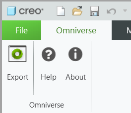
Clicking this menu will reveal the ribbon panel for Omniverse Interactions.
Option |
Description |
|---|---|
About |
Displays version and other useful information regarding the Omniverse Creo Connector. |
Export |
Opens the export UI. |
Help |
Directs users to this page. |
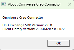
About
Simple informational dialogue displaying relevant Omniverse Creo Connector version information.
Export
Opens the export UI, from which you can configure and launch your export.
Simply press the export button to reveal the configuration window:

You can select your location to export on the left hand side of the window, and configure your export further with settings on the right.

Option |
Description |
|---|---|
Instancing Style |
Displays version and other useful information regarding the Omniverse Creo Connector. |
Units |
The unit system you want your export to be in. Set to Use Model Units to use the model’s native units. |
Materials |
Whether or not to export MDL and UsdPreviewSurface materials embedded in your .usd file. |
Material Mapping |
Whether or not to enable to the material mapping feature. |
Run Optimization |
Whether or not to run scene optimization on the exported file. |
Checkpoint Comment |
An optional message which is displayed with the checkpoint indicated the completed export of this model. |
Instancing Style
Creo models are often assemblies containing many assemblies and parts. This setting configures how the multiple use of assemblies and parts are handled:
None: The model is “flatly” exported into a single file, where every part instance has its own unique polymeshes.
Internal: Parts and assemblies are converted once within the file and are instanced everywhere they are used.
External: Parts and assemblies are converted once as separate USD files residing at the Components folder beside the exported file, and referenced as payloads.
Note
Flexible components, or components which share the same underlying part or assembly but have modifications when instanced, may not export correctly when using Internal or External instancing. If your model’s components do not export as expected, we recommend using the None setting to ensure the correct conversion of such parts.
Units
Sets the MPU (meters per unit) unit system of the exported file.
Materials
When enabled, MDL and UsdPreviewSurface materials are created for your meshes. If disabled, only the mesh’s display color is exported.
Material Mapping
Rather than creating new materials on every export, users can correspond their premade MDL materials in Omniverse to their Creo materials and assign them automatically on export.
When the connector is installed, a file is copied to the path:
\Users\[username]\Documents\Omniverse\Creo\MaterialMapping\omniverseMDLtable.csv
This table maps material names in Creo to corresponding sample materials in your installation of Omniverse Nucleus.
When the Material Mapping feature is enabled, meshes with the materials in the first column of this map will not convert their materials into MDL and UsdPreviewSurface materials. Instead, they will reference the material linked in the second column with the MDL subidentifier denoted in the third.
Users can add their own mappings by duplicating this table.
Note
We recommend duplicating this table rather than editing it as installs and updates of the Creo Connector may overwrite this file.
Run Optimization
Scene Optimization utilizes core optimization libraries found in the standalone application and kit extension that performs scene optimizations at the USD level. This allows complex scenes to be converted into more lightweight representations which can be displayed and evaluated more quickly.
The integration provides various processes which can be used individually or in combination stack to optimize a scene. A few base configurations have been provided in the connector to optimize the data prior to sending to your preferred Kit Application.
Users can add their own scene optimizer configurations by adding .json files to this path of their connector installation:
\Users\[username]\AppData\Local\ov\pkg\creo-connector_[Creo Version]_[Connector Version]\connect_scene_optimizer_configs
Please see the Scene Optimizer user manual for information on the optimization operations and how to create custom configuration files.
Checkpoint Comment
You can provide an optional message which is displayed with the checkpoint indicated the completed export of this model and is viewable with Omniverse Kit UIs and other Omniverse applications.
Logging
You can troubleshoot exports by viewing the logs created at this path:
\Users\[username]\.nvidia-omniverse\logs\connect-sdk\Creo-[Connector Version]\omni.connect.ptccreo-[Connector Version]
To change log verbosity, you can edit the .toml file at this path:
\Users\[username]\AppData\Local\ov\pkg\creo-connector_[Creo Version]_[Connector Version]\config\omni.connect.client.toml
Find the following within the .toml file and set channels.”” = * to Error, Warning, Info or Verbose.

Note
Decreasing severity will increase the amount of log output. Setting to “Error” will result in only logging Errors, whereas setting it to “Verbose” will log everything.
Converting from the Command Line
Users can also use the command line to convert their Creo models by running the provided convert.bat located at the installation location of the connector. Arguments largely correspond to options in the export window.
Usage:
[Path_to_creo_connector_install]\convert.bat [Path_to_creo_parametric_exe] [Arguments_semicolon_separated]
Example:
convert.bat "C:\Program Files\PTC\Creo 8.0.0.0\Parametric\bin\parametric.exe" --file C:\Dev\tests\inputs\Creo8\centeredblock.prt;--output C:\Dev\tests\outputs\Creo8;--extension .usdc
This will export the centeredblock.prt file to C:\Dev\tests\outputs\Creo8\centeredblock.usdc.
Required Arguments:
Arg |
Description |
Possible Values |
|---|---|---|
–file |
The full path to the file to convert. |
Any file path without whitespace ending strictly in .prt or .asm |
–output |
The directory to output to. Filename will match the input file’s name. |
Any valid directory path |
–extension |
Export file extension. |
.usd, .usda, .usdc |
Note
Path arguments cannot contain any whitespace, and versions in file extensions such as .5 in .prt.5 must be omitted when using this feature.
Optional Arguments:
Arg |
Description |
Possible Values |
|---|---|---|
–unitSystem |
The unit system you want your export to be in. Set to Use Model Units to use the model’s native units. |
See https://openusd.org/release/api/class_usd_geom_linear_units.html |
–instancingStyle |
Displays version and other useful information regarding the Omniverse Creo Connector. |
External, Internal, None |
–exportMaterials |
Whether or not to export MDL and UsdPreviewSurface materials embedded in your .usd file. |
True, False |
–materialMapping |
Whether or not to enable to the material mapping feature. |
True, False |
–optimize |
Path to scene optimization file. |
Any file path to a valid scene optimization .json file |
–comment |
An optional message which is displayed with the checkpoint indicated the completed export of this model. |
Any text |
Recreating the Shortcut
If you lose your shortcut, you can simply reinstall the connector, or follow the steps to recreate the desktop shortcut manually:
Right click on your desktop (or any folder)
New / shortcut
Set the location to your creo install folder (path above)/launch_creo.bat
Finish creating the shortcut
Right click on the new shortcut and hit Properties
Change the Start-in path to the install folder of your connector install (path above)