User Manual
Install the Connector
Follow our Connector installation instructions to install this connector.
Note
Before installing the Omniverse Alias Connector from your Workstation Launcher, make sure you have a compatible version of Autodesk Alias installed.
User Interface
The Alias Connector brings Autodesk Alias into the Omniverse Platform through the use of NVIDIA Omniverse™ Connect tools similar to other NVIDIA Omniverse™ Connect applications.
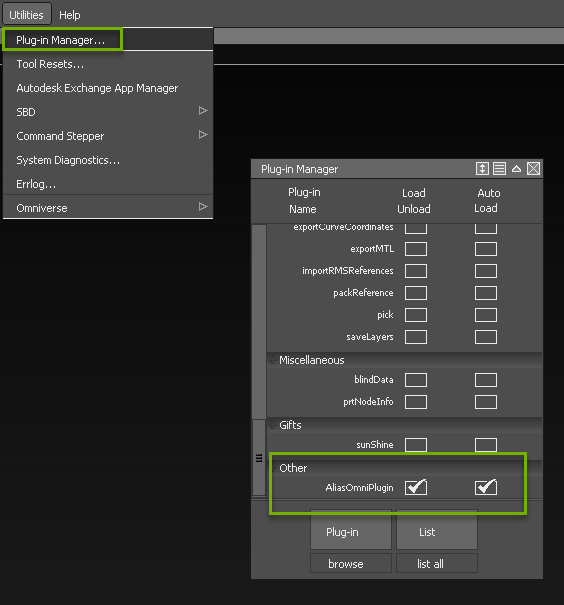
Once installed, the Connector will be enabled automatically with all compatible Autodesk Alias versions. To confirm that the Connector is enabled, in Autodesk Alias and navigate to Utilities > Plug-in Manager. Scroll down to section Other. The Omniverse Alias Connector Plugin should be listed.
Note
We recommend keep Auto Load checked, otherwise the plug-in will have to be reinstalled for the next start of Autodesk Alias because it won’t be listed in the Plug-in Manager.
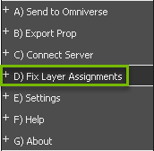
Now you will find the Omniverse menu under Utilities > Omniverse.
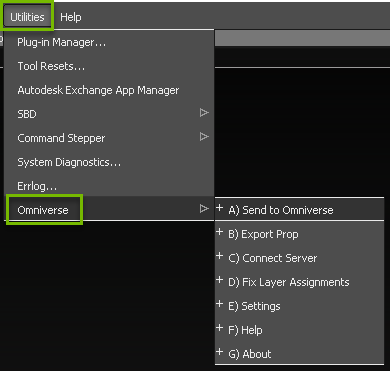
Clicking this menu will reveal the ribbon panel for Omniverse Interactions.
Option |
Description |
|---|---|
Send to Omniverse |
Sends the scene directly to your chosen Kit Application for viewing. |
Export Prop |
Exports scene as a prop (No project container) to be used within a project. |
Connect Server |
Allows sign in to an Omniverse NVIDIA Omniverse™ Nucleus Server. |
Fix Layer Assignments |
Automatic layer reassignment for group nodes and child nodes. |
Settings |
Adjust connections and settings of the Omniverse Alias Connector. |
Help |
Directs users to this page. |
About |
Displays version and other useful information regarding the Omniverse Alias Connector. |
Send to Omniverse
This feature is deprecated and will be removed within the next release, since you now are able to write directly to a Nucleus server or file system using the new file picker. See Export Prop to learn more about the file picker.
Export Prop
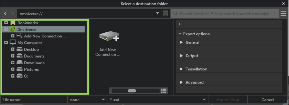
This menu item will open the file picker and give you some options on export. The Alias data will be converted into a USD file and stored in the specified location.
The location can either be a local file system or a Nucleus server. This information can be found on the left side of the window.
You can enter any valid nucleus server here and give it the name of your choice.
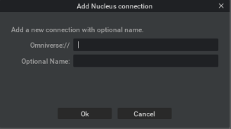
After clicking OK, the server will appear in the user interface.
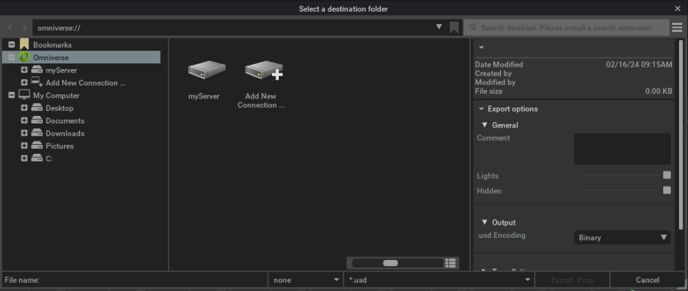
Export options can be found on the right side of the window:
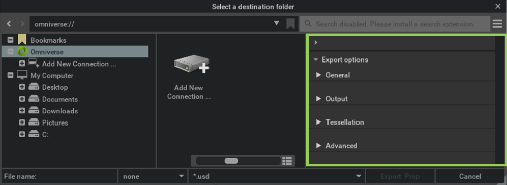
Learn more about each export option using the drop-downs below.
General
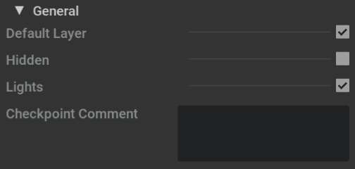
This section holds specific settings for the Alias scene handling.
Default Layer
When enabled, the content of the default layer will be included. If it is not checked, the default layer will not be exported.
Hidden
If there is hidden geometry in your Alias file, it will be exported as well and tagged as invisible in the USD file.
Lights
If you check this, all the lights that exist in the Alias Scene are exported into the USD file.
Checkpoint Comment
The text entered in that field will be written into the comment section of a checkpoint stored in a Nucleus environment. You may want to use that to document changes in the file when overwriting a USD file.
Output
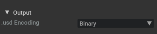
This menu item controls how the file is written to disk. Note that USD files can have multiple suffixes: .usd, .usda, .usdc. USD files with the extension .usd can be Binary or ASCII. The decision which format will be chosen is defined here.
This setting will be ignored when choosing:
.usda (then the file will always be exported in ASCII)
.usbc` (then the file will always be exported as binary)
Binary
If the extension .usd` is selected in the file picker on export, the generated USD file will be exported as binary.
Text
If the extension .usd` is selected in the file picker on export, the generated USD file will be exported as readable file (ASCII).
Tesselation
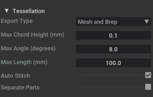
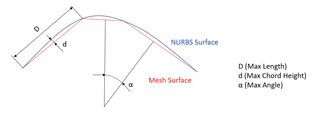
This section holds the controls for the tessellation settings. Here is a visual to get a better understanding of the parameters.
Export Type
This setting defines the data being written into the USD file. Since Alias is a surface modeler based on NURBS, those must be processed into polygons for various reasons. The tessellation settings define how precise that mesh represents the NURBS surfaces. If Breps are exported, the relation between NURBS and the derived mesh will be kept and at any time those Breps can be retessellated using Scene Optimizer. You can choose between:
Mesh and Brep This will write out messhes and keeps the surface data around in the USD file.
Brep Only Only the surface data is written out to USD (You will not see any geometry in the viewport until you tesselate them, e.g. with Scene Optimizer).
Mesh Only Only the tesselated mesh data is written to USD.
Max Chord Height
The maximum deviation of the tessellated geometry to the original surface data (see image above). A smaller value will end up with a more precise mesh.
Max Angle
The maximum angle between polygon faces (see image above). A smaller value will end up with a more precise mesh.
Max Length
The maximum length of a polygon’s edge (see image above). Limit the length to avoid long small polygons, which are bad for rendering and other simulation use cases.
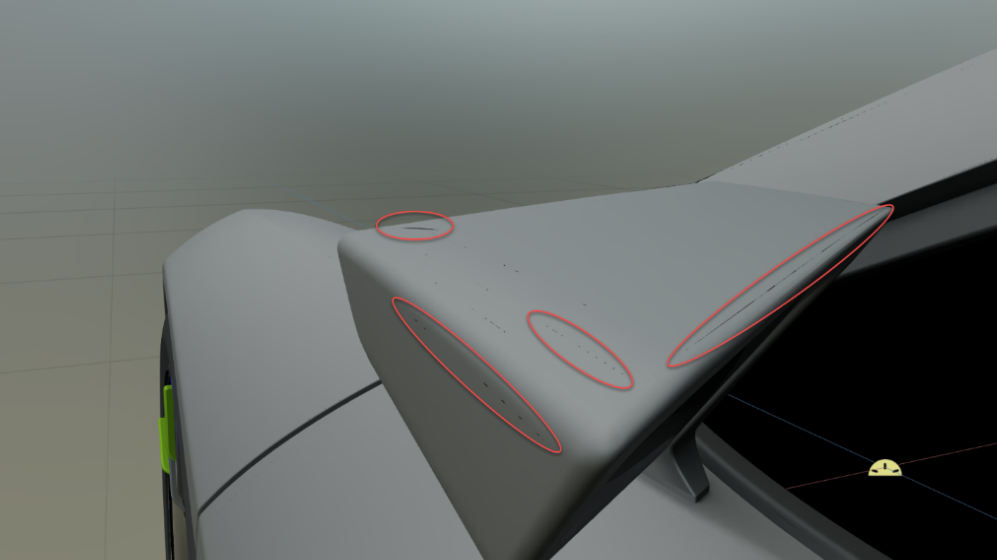
Auto Stitch
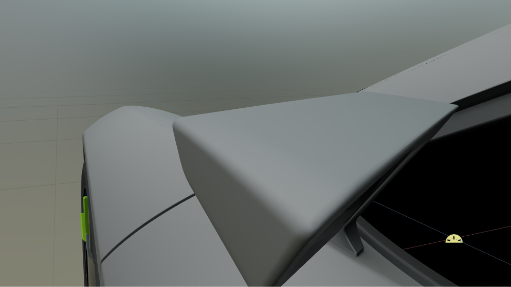
When Auto Stitch is enabled, a topology will be generated and then tesselated. Stitching is used to generate a topology so that the system knows about adjacent surface patches. This turns a loose NURBS-based model into a Brep. With that information, the algorithm can tessellate over surface boundaries and avoid cracks as well as double vertices to create watertight meshes.
Please note: For Auto Stitch, the surfaces must be in the same group and have the same material so that they can be stitched together. The stitching tolerance defines the accepted gap size for stitching and the separate part function.
Note the gaps due to different surface parametrization:
Note the watertight mesh:
Separate Parts
Sometimes, even if surfaces are in the same group and share the same material, it might not be desired to have them in one mesh. Therefore, you need to separate the parts.
A good example might be a car door. If you do not separate the parts, you may not be able to animate the door since the geometry of the windowpanes will not have their own transforms. This behavior is controlled with the Separate Parts flag.
Advanced
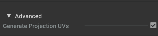
This section defines some advanced workflow settings that also add information to the Alias file.
Generate Projection UVs
With the latest release of Omniverse Alias Connector, we implemented base UV coordinate generation. As default, we use box mapping. The generated UV coordinates provide additional information to the tessellated meshes and allow proper texture support when applying materials in downstream applications. The size has been defined on a 10 x 10 cm box. Again, if that UV assignment is not fitting your needs, Scene Optimizer can be used to reassign UVs with even more projection methods.
Exporting the file
After defining the file location and parameters, you are now ready to export your data. You must enter a valid file name and select a file format (Refer to the Output tab above to learn about the file format settings). Click Export Prop to start the export.
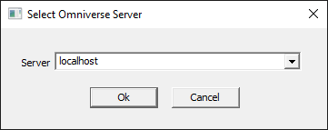
Connect Server
Allow users to connect to an existing NVIDIA Omniverse™ Nucleus server you want, or choose between existing NVIDIA Omniverse™ Nucleus servers.
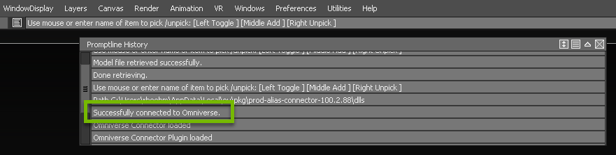
When the connection is established, in Autodesk Alias you can see a notification in the Promptline History. By selecting the symbol on the far left side you can expand and scroll through the history.
Setting |
Result |
|---|---|
Server |
Address of Omniverse Nucleus Server
|
Ok |
Begins the Connection with Selected User/Server
|
Cancel |
Stops the Sign-In Process and Closes the Sign-In Window
|
Note
The live sync feature is not implemented in this Omniverse Alias Connector version.
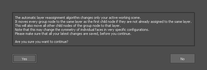
Fix Layer Assignments
For USD exports this feature allows you to reassign layers in Autodesk Alias before the export. This will change your currently open scene and will only be stored permanently after saving the scene.
After executing the function, a message box appears explaining what changes will be made. This note can be confirmed with Yes or No.
After successful execution, a message window appears which must be confirmed.
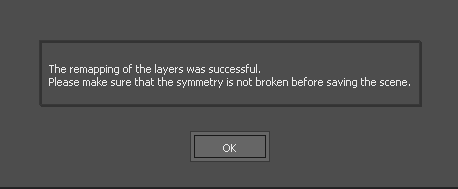
Note
The changes will become permanent only after saving in Autodesk Alias.
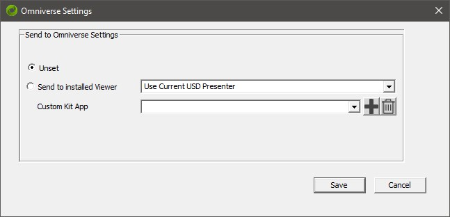
Settings
The settings dialog allows you to select a preferred Kit Application install as your viewer and to edit other settings.
Note
You will need to have your preferred Kit Application installed and selected to use Send to Omniverse feature in Autodesk Alias.
Omniverse Settings |
Description |
|---|---|
Unset |
No App Settings (This setting disables Send to Omniverse) |
Send to installed Viewer |
Choose between different Kit Application Launch Path. |
Custom Kit Application |
Allows selection of custom Kit Applications not found automatically. |
Save |
Commits the Changes and Closes the Window. |
Cancel |
Closes the Window and Discarding the Changes. |
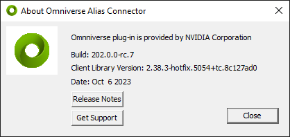
About
The About dialog shows the current version information, and provides helpful links to access Release Notes and to Get Support
Button |
Description |
|---|---|
Release Notes |
Directs you to Omniverse Alias Connector release notes on this page.
|
Get Support |
Directs you to our Developer Forum
|
Close |
Closes About window.
|
Command Line Interface
Export from Autodesk Alias can also be performed using a Command Line Interface. You can convert single Autodesk Alias files or multiple files in a source folders into a target folder. The Autodesk Alias files will be converted and the same subfolder structure recreated in your target folder to avoid file name collision.
Open a Powershell and execute this command in the Connector installation LIB folder. The LIB folder usually can be found in: C:\Users\USERNAME\AppData\Local\ov\pkg\alias-connector-203.0.0-rc.2\lib
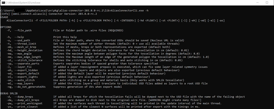
Run the command and first you will get information how to use it and a list of all available options:
.\AliasConnectorCli -h
The LIB folder usually can be found in:
C:\Users\USERNAME\AppData\Local\ov\pkg\alias-connector-203.0.0-rc.2\lib\
Path to .exe file:
../lib/AliasConnectorCli.exe
You can give the Command Line Interface a source and target folder location and it will iterate over all .wire files converting them to the target folder. If you do not provide a target folder location, it creates the USDs next to the original Autodesk Alias files.
Note
You will need to have Autodesk Alias installed on the same system.